1
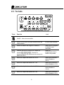
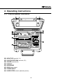
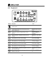
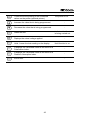
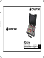
Formato: 135mm x 190mm
Megóhmetro Digital
Manual de uso
P. 03
Digital Insulation Tester
User guide
P. 37
MD-5060e
Megóhmetro digital
Manual de uso
GU-1388
3
Precauciones de Seguridad
• Deberán leerse y comprenderse las Precauciones de Seguridad y el Manual de
Uso antes de usar el instrumento.
• Respete rigurosamente las normas de seguridad para el trabajo con alta tensión
cuando utilice este equipo. Las tensiones generadas son peligrosas.
• Nunca conecte o desconecte las puntas de prueba con el instrumento en
funcionamiento o mientras el indicador luminoso de Alta Tensión está encendido.
Si tiene que hacer alguna modificación al conexionado hágala con el equipo
apagado.
• No haga cortocircuitos entre los bornes de salida de alta tensión y los bornes +R
o Guard mientras el instrumento está funcionando. Esto puede ser peligroso
para el operador.
• Antes de conectar el instrumento verifique, usando pértigas adecuadas, que no
existan potenciales peligrosos en los puntos a los que se conectará.
• El panel del equipo, bornes y conectores deben mantenerse secos y limpios.
Este equipo debe ser operado únicamente por personas calificadas,
aplicando rigurosamente las normas de seguridad pertinentes.
Símbolos utilizados en el equipo
Atención, riesgo de descarga eléctrica.
Atención, referirse al Manual de uso.
El equipo está conforme con las directrices actuales de la U.E.
4
Índice
1. Descripción ........................................................................................................... 6
2. Instrucciones de uso ............................................................................................. 7
2.1. Función de los controles del panel................................................................ 7
2.2. Teclado ......................................................................................................... 8
2.3. Indicadores .................................................................................................. 10
2.3.1. Display .................................................................................................. 10
2.3.2. Escala analógica de barras (bargraph) ................................................ 10
2.3.3. Indicador luminoso de alta tensión ....................................................... 10
2.3.4. Cronómetro incorporado ....................................................................... 10
2.3.5. Número del ensayo .............................................................................. 10
3. Alimentación ....................................................................................................... 11
3.1. Verificación del estado de la batería ........................................................... 11
3.2. Cargador de batería .................................................................................... 12
4. Conectando el equipo ......................................................................................... 13
4.1. Uso del borne “Guard” (G) .......................................................................... 14
5. Configurando los ensayos .................................................................................. 15
5.1. Tensión de prueba ...................................................................................... 15
5.2. Timer ........................................................................................................... 16
5.3. Límite (LIM) ................................................................................................. 17
5.4. Voltímetro .................................................................................................... 18
5.5. Hold ............................................................................................................. 18
5.6. Filtro (FILTER) ............................................................................................ 18
5.7. Índice de polarización (PI) ........................................................................... 19
5.8. Índice de absorción dieléctrica (DAI) .......................................................... 20
5.9. Memoria ...................................................................................................... 20
5.10. Auto-apagado ............................................................................................ 20
6. Realizando mediciones ...................................................................................... 21
7. Software.............................................................................................................. 22
7.1. Instalando los drivers USB .......................................................................... 22
7.2. Software CIR Logger ................................................................................... 25
®
7.3. HyperTerminal - Transferencia en tiempo real .......................................... 26
7.3.1. Número del puerto COM ...................................................................... 26
7.3.2. Iniciando el HyperTerminal ................................................................... 28
8. Impresora (opcional) ........................................................................................... 31
9. Especificaciones técnicas ................................................................................... 32
10. Boletín técnico 32 ............................................................................................. 34
5
1. Descripción
El megóhmetro digital inteligente CIRCUTOR modelo MD-5060e, es un
equipo de gran versatilidad, robusto y fácil de utilizar. Emplea una
tecnología de probada eficacia, que proporciona mediciones confiables,
seguras y precisas de resistencias de aislamiento de hasta 5.000.000 MΩ
@ 5 kV, con 4 tensiones de prueba preseleccionadas: 500 V - 1 kV 2,5 kV - 5 kV, con posibilidad de aumentar o disminuir estos valores en
pasos de 500 V.
El equipo está controlado por un microprocesador, lo que facilita su
operación y permite la introducción de funciones avanzadas tales como:
Selección automática del rango, memoria para hasta 4000 mediciones,
voltímetro, medición automática de los índices de polarización y de
absorción dieléctrica, “Timer” para programar el tiempo del ensayo de
resistencia, “Límite” que permite realizar ensayos del tipo “Pasa / No
pasa” con límite programable, reloj en tiempo real, calendario para
identificación de las mediciones y cronómetro incorporado indicando el
tiempo transcurrido desde el inicio del ensayo en minutos y segundos.
La interface USB permite la comunicación del equipo con una
computadora para transmitir los datos registrados. El software
CIR Logger, analiza los resultados y los presenta por medio de gráficos y
tablas, generando automáticamente el protocolo de ensayo.
Otra característica destacada de este megóhmetro son las tensiones
negativas en referencia al borne de potencial cero (R), para detectar
humedad en las instalaciones por el efecto de electroendosmosis.
Por
sus
características
constructivas
este
instrumento
es
extremadamente robusto, con excelente desempeño tanto en laboratorio
como en los trabajos de campo, en condiciones ambientales rigurosas.
6
2. Instrucciones de uso
2.1. Función de los controles del panel
- Borne de SALIDA DE TENSIÓN (-V)
- Borne de REFERENCIA CERO (+R)
- Borne GUARD (G)
- DISPLAY
- TECLADO
- Interface USB
- ENTRADA DE ALIMENTACIÓN
- Control de ALIMENTACIÓN DEL PAPEL (Impresora opcional)
7
2.2. Teclado
Tecla
Función
Led
On/Off - Llave de encendido.
-
Activa el filtro que minimiza interferencias de
ruido externo.
El filtro está activado.
Exhibe el estado de carga de la batería.
Indica que el cargador
de batería está
actuando.
Habilita las teclas de selección rápida de
tensión . Permite la
programación de las tensiones de ensayo en
pasos de 500 V.
Modo de
programación de la
tensión de prueba.
Selección rápida de tensión de 500 V.
Indica que la tensión
seleccionada es
500 V.
Selección rápida de tensión de 1 kV.
Indica que la tensión
seleccionada es 1 kV.
Selección rápida de tensión de 2,5 kV.
Indica que la tensión
seleccionada es
2,5 kV.
Selección rápida de tensión de 5 kV.
Indica que la tensión
seleccionada es 5 kV.
8
TIMER. Permite la programación del la duración Está habilitada la
del ensayo.
selección de Timer.
Permite la programación del límite para el
ensayo “Pasa / No pasa”.
Está habilitada la
selección de Límite.
Enciende / Apaga la impresión de los valores
medidos (impresora opcional).
La impresora está
activada.
Aumenta el valor que está siendo programado.
Disminuye el valor que está siendo programado.
Start. Inicia el ensayo.
Exhibe la tensión efectivamente aplicada.
Indica que está siendo
ejecutado el ensayo.
Congela en el display la última lectura.
El valor mostrado en
el display está
congelado.
Muestra el valor del Índice de Polarización.
-
Muestra el valor del Índice de Absorción
Dieléctrica.
-
Stop. Fin del ensayo.
-
9
2.3. Indicadores
2.3.1. Display
Display alfanumérico LCD donde es exhibido el resultado de la medición,
el tiempo transcurrido desde el inicio de la medición, el n° de ensayo, la
tensión de ensayo seleccionada, la indicación analógica por bargraph y
mensajes al operador (en inglés).
2.3.2. Escala analógica de barras (bargraph)
El equipo indica analógicamente el valor de la resistencia que se está
midiendo. El bargraph proporciona una visualización de la variación
gradual del valor de la resistencia de aislación durante el transcurso del
ensayo.
2.3.3. Indicador luminoso de alta tensión
Indica la presencia de ALTA TENSIÓN en el borne de salida.
Permanece encendido hasta que las capacidades, tanto internas
del equipo como las externas, sean descargadas por el propio
megóhmetro.
2.3.4. Cronómetro incorporado
Posee indicación del tiempo transcurrido en minutos y segundos.
2.3.5. Número del ensayo
Los ensayos son numerados automáticamente por el megóhmetro para
facilitar su identificación.
10
3. Alimentación
El MD-5060e se alimenta mediante una batería recargable interna de
12 V - 2,3 Ah.
3.1. Verificación del estado de la batería
Durante la medición es posible verificar el estado de la batería. Para eso
se debe mantener oprimida la tecla y verificar la indicación en el
display. Será indicado BAT. OK si la carga fuera suficiente, o LOW BAT
en el caso de que la batería precisa ser recargada. La escala analógica
de barras (bargraph), da una idea aproximada del porcentaje de carga
remaneciente (mínimo de 20% para operación normal).
Cuando la carga de la batería alcanza el valor mínimo de operación
normal aparece automáticamente el mensaje LO BAT en el área en que
se indica el valor de tensión de ensayo, alternándose con la misma cada
1 segundo.
11
3.2. Cargador de batería
El equipo posee incorporado un circuito inteligente que controla el
proceso de carga de la batería, pero que no permite el funcionamiento
del equipo cuando conectado a la red. Para cargar la batería siga el
siguiente procedimiento:
•
•
Verifique que la llave On/Off esté en Off ().
Conecte el equipo a la red de energía eléctrica a través de la fuente de
alimentación. Después de un instante, el indicador luminoso carga de
la batería (led de la tecla ) brillará alternadamente en los colores
verde y rojo durante un segundo, mientras el cargador verifica el estado
inicial de la batería para seleccionar los parámetros optimizados de la
carga.
Significado de las indicaciones luminosas
Luces verde y roja
Evaluación del estado inicial de la batería al enchufar la
brillando alternadamente fuente, durante un segundo.
Luz roja permanente
Batería en carga.
Luz roja intermitente
La batería está recibiendo poca carga.
Luz verde permanente
Carga finalizada con éxito. Batería OK.
Luz verde intermitente
El proceso de carga terminó sin embargo la batería no
recibió la carga completa.
Al final de su vida útil, la batería debe ser reciclada o colocada en lugar
apropiado, para proteger el medio ambiente.
La batería recargable no presenta “efecto memoria” por lo que puede ser cargada
tantas veces como se desee. En cambio, su vida útil se reduce sensiblemente si
se permite que permanezca totalmente descargada. Para evitar este efecto cargue
la batería antes de almacenar el equipo y no deje pasar más de 30 días sin repetir
el proceso de carga, aunque el instrumento no haya sido utilizado (La batería
pierde parte de su carga estando almacenada).
12
4. Conectando el equipo
Atención: todos los procedimientos abajo deben ser realizados con el
equipo apagado, para mayor seguranza del operador.
Asegúrese que no existan diferencias de potencial entre los puntos a los
cuales se conectará el megóhmetro, ni entre ellos y tierra.
Conecte el terminal de seguridad del cable rojo al borne de salida de
tensión -V del megóhmetro. Conecte el terminal BNC del cable negro al
borne de REFERENCIA CERO (+R) y los terminales cocodrilo al
elemento a medir como indica la figura abajo.
Las puntas de prueba en el dibujo son meramente ilustrativas
13
4.1. Uso del borne “Guard” (G)
Según la medición que se vaya a realizar, puede emplearse o no el borne
G (Guard). Durante las mediciones, el megóhmetro debe estar
eléctricamente referido a tierra para evitar que el equipo quede a un
potencial elevado lo que provoca lecturas inestables. Cuando se mide
aislamiento respecto de tierra, el borne R está conectado a tierra y se
cumple la condición de fijar el potencial del equipo. En cambio, cuando la
medición se realiza entre dos puntos que no están conectados a tierra
(por ej., entre dos conductores de fase en un cable trifásico) el borne
GUARD del megóhmetro debe conectarse a tierra. Esto implica que
siempre que se mide, uno de los bornes GUARD o R debe estar
conectado a tierra, pero no ambos simultáneamente.
El Boletín Técnico 32 explica el uso del borne GUARD para minimizar el
efecto de resistencias parásitas, cuya influencia sobre la medición se
desea evitar.
14
5. Configurando los ensayos
5.1. Tensión de prueba
Para definir el valor de la tensión de prueba, es necesario seleccionar la
tecla de ayuste de tensión . Esta tecla habilita tanto la selección de
las tensiones pre-programadas ( ) cuanto las teclas y , que disminuyen o aumentan el valor de la tensión de prueba en
500 V. Para salir del modo de selección de tensión de prueba, presione
nuevamente la tecla de ayuste .
15
5.2. Timer
Presione la tecla y utilice las teclas o para definir a duración
del ensayo en 30 seg, 1 min, 3 min, 10 min o 30 min. En el display
aparece el tiempo definido. Esta programación debe ser hecha antes de
iniciar el ensayo. Oprimir la tecla durante el ensayo permite apenas
visualizar o valor seleccionado. Presione a tecla para confirmar el
valor seleccionado.
Para volver al modo normal, presione la tecla y con las teclas o
seleccione la opción “ - - - ”.
16
5.3. Límite (LIM)
Presione la tecla para determinar el límite inferior de aislación para
ensayos del tipo “Pasa / No pasa”. Seleccione este valor usando las
teclas y ; los valores posibles son 10 MΩ, 100 MΩ, 1 GΩ o
10 GΩ.
Durante un ensayo “Pasa / No pasa”, el MD-5060e indicará con un BIP
intermitente y con el led de la tecla parpadeando cuando la
resistencia de aislación sea inferior al límite programado. El led de la
tecla permanecerá parpadeando hasta el fin de los ensayos, o hasta
que el valor de la resistencia medida sea superior al límite programado.
Para volver al modo normal, presione la tecla y con las teclas o
seleccione la opción “ - - - ”.
17
5.4. Voltímetro
Oprimiendo la tecla , el equipo medirá la tensión efectivamente
aplicada al elemento bajo ensayo.
5.5. Hold
La tecla permite retener en el display la última lectura efectuada en
el instante en que se oprimió esta tecla sin interrumpir el ensayo. Al
liberarse la tecla , el megóhmetro actualiza los valores de resistencia
y tiempo. El led de la tecla encendido y la letra H en el display,
indican que fue activada esta función.
5.6. Filtro (FILTER)
Cuando se realizan mediciones en transformadores o en máquinas de
grandes
dimensiones,
en
presencia
de
grandes
campos
electromagnéticos, es posible que la lectura del equipo sea inestable,
especialmente para valores de resistencias mayores que 100 MΩ. En
estos casos es conveniente presionar la tecla antes de iniciar la
medición. Esta función permite llegar al valor de resistencia de
aislamiento en una curva ascendente sin grandes oscilaciones.
18
5.7. Índice de polarización (PI)
La tecla permite ver el valor del Índice de Polarización. El
megóhmetro debe quedar conectado, aplicando tensión a la muestra,
durante 10 minutos. Después de ese tiempo el operador debe oprimir la
tecla para que el megóhmetro indique el valor del índice de
polarización.
Si se anticipa a oprimir la tecla antes de transcurrido 10 minutos el
display indicará PI = - - - .
El índice de polarización es el cociente entre el valor de la resistencia de
aislamiento medido a los 10 minutos y el valor medido a 1 minuto. Este
índice es muy útil en el mantenimiento predictivo y preventivo para
detectar la deterioración de la resistencia de aislamiento por la presencia
excesiva de polvo, suciedad, grasas o la acción de agentes químicos /
físicos, etc.
19
5.8. Índice de absorción dieléctrica (DAI)
La tecla permite visualizar el valor del Índice de Absorción
Dieléctrica. El megóhmetro debe quedar conectado, aplicando tensión a
la muestra, durante 1 minuto (60 segundos). Después de ese tiempo, el
operador debe oprimir la tecla para leer el valor del índice de
absorción.
Si se anticipa a oprimir la tecla antes de transcurrido 1 minuto el
display indicará DAI = - - - . El Índice de Absorción Dieléctrico es el
cociente entre el valor de la resistencia de aislamiento medido a los 60
segundos y el valor medido a los 30 segundos y es útil en el
mantenimiento preventivo y predictivo de bobinados (de transformadores,
motores, generadores, etc.).
5.9. Memoria
Este equipo tiene una memoria interna para hasta 4000 valores de
medición. Esta memoria es administrada por el equipo de modo cíclico.
Cuando la memoria este completa, a medida que se van realizando
nuevos ensayos se van borrando definitivamente los más antiguos. Por
razones de precaución, siempre descargue la memoria del equipo para
una computadora cuando terminar los ensayos.
5.10. Auto-apagado
La función de auto-apagado (Auto-Power-off) desactiva el consumo del
equipo en dos situaciones:
• Durante una medición: Después de 35 minutos de funcionamiento sin
que, durante este período, sea ejecutada la función de verificación del
estado de la batería.
• Equipo ocioso: Después de 10 minutos de inactividad.
20
6. Realizando mediciones
Oprima la tecla . Inmediatamente el led de ALTA TENSIÓN
se enciende indicando que el generador interno del megóhmetro
está aplicando la tensión al elemento bajo ensayo. Luego el
display mostrará el n° del ensayo, el valor de la tensión y iniciará
el conteo del tiempo transcurrido.
Durante algunos segundos el sistema de auto-rango buscará el rango
más conveniente para el valor que está midiendo. En ese tiempo el
display mostrará el mensaje:
Si el valor estuviera dentro del alcance del instrumento, la indicación del
n° de ensayo dará lugar para la indicación del valor de la resistencia y su
unidad correspondiente, y iniciará la indicación analógica por bargraph.
Si el valor medido sobrepasa 5 TΩ @ 5 kV, el mensaje será:
21
7. Software
7.1. Instalando los drivers USB
Para instalar los drivers USB necesarios para la comunicación entre la
computadora y el equipo, siga el procedimiento abajo:
1. Inserte el CD-ROM, fornecido con el equipo, en el lector de CD de la
computadora.
2. Conecte el equipo a computadora a través del cable de comunicación
USB.
3. El sistema operativo Microsoft Windows® reconocerá automáticamente el equipo.
4. Será exhibida la ventana “Asistente para hardware nuevo
encontrado”. Seleccione a opción “No por el momento” y haga clique
en Siguiente.
22
5. Seleccione a opción “Instalar automáticamente el software” y haga
clique en Siguiente.
6. En la ventana “Instalación de hardware” haga clique en
Continuar.
23
7. Será iniciada a instalación de los drivers USB.
8. Para finalizar la instalación, haga clique en Finalizar.
24
Después del término de la instalación de los drivers USB, será necesario
repetir el procedimiento anterior para la instalación de un puerto COM
virtual.
7.2. Software CIR Logger
Este software facilita la comunicación entre el equipo y una computadora
con sistema operacional Windows. Permite sincronizar la fecha y hora del
reloj interno del equipo con la fecha y hora de la computadora, transferir
los dados almacenados, limpiar la memoria, transferir en tiempo real los
valores medidos, generar gráficos y protocolos de ensayos, etc. Las
instrucciones de instalación y uso están incluidas en el propio software.
25
7.3. HyperTerminal® - Transferencia en tiempo real
Caso necesite transferir los datos almacenados en la memoria para la
computadora, debe-se usar el software CIR Logger.
Para transferir en tiempo real los valores medidos por lo equipo para una
computadora, a través del software HyperTerminal, utilice el cable USB
fornecido con los accesorios.
7.3.1. Número del puerto COM
Para realizar la comunicación entre equipo y HyperTerminal es necesario
determinar el número del puerto COM a ser utilizado. Siga el
procedimiento abajo (el equipo debe estar conectado a computadora):
1. Haga clique en menú Inicio / Todos los programas / Panel de
control
26
2. En la ventana “Panel de control”, haga clique en Sistema.
3. En la ventana “Propiedades del sistema”, haga clique en Hardware /
Administrador de dispositivos.
27
4. En la ventana “Administrador de dispositivos” verifique cual el número
del puerto COM está atribuido al equipo.
7.3.2. Iniciando el HyperTerminal
1. Haga clique en menú:
Inicio / Todos los programas / Accesorios / Comunicaciones /
HyperTerminal
2. Para criar una nueva conexión, elija un nombre, seleccione un ícono y
haga clique en “Aceptar”.
28
3. En la ventana siguiente, seleccione el puerto de comunicaciones
adecuado.
4. Seleccione los siguientes datos en la ventana próxima: Bits por
segundo: 4800, Bits de datos: 8, Paridad: Ninguno, Bits de parada: 1,
Controle de flujo: Ninguno.
29
En este momento la computadora está lista para recibir las informaciones
de la medición. Al oprimir la tecla el equipo comenzará a enviar los
datos a la computadora.
30
8. Impresora (opcional)
Para habilitar la impresora, oprima la tecla . Los valores medidos
serán impresos cada 15 segundos. El Índice de Absorción Dieléctrico y el
Índice de Polarización serán impresos después de 1 minuto y 10 minutos
respectivamente. La impresión puede ser iniciada o terminada en
cualquier momento durante el ensayo, no obstante es conveniente
habilitar la impresora antes de iniciar el ensayo para sea impreso
completo, incluido el encabezamiento.
ATENCIÓN: No tire del papel, siempre use la tecla de Control de alimentación de
papel. Nunca intente introducir el papel de vuelta para la impresora. En cualquier
de estos casos la impresora puede dañarse fácilmente.
Esta impresora utiliza papel térmico, 37 mm de ancho, en una bobina de
hasta 33 mm de diámetro. La figura abajo muestra cómo colocar el papel.
Oprima la tecla Control de alimentación hasta el papel aparecer. Para
retirar la bobina de papel antigua, corte el papel cerca de la bobina y
oprima la tecla Control de alimentación. Las operaciones de retirada de
la bobina usada deben ser efectuadas de esta manera por que el
movimiento del papel es unidireccional, o sea, el papel se mueve
solamente en una dirección.
31
9. Especificaciones técnicas
Tensiones de prueba
: 0,5 kV - 1 kV - 2,5 kV - 5 kV con selección
rápida. 0,5 kV hasta 5 kV en pasos de 500 V
Tensión continua, negativa respecto de tierra.
Alcance
: 5 TΩ @ 5 kV
Corriente de cortocircuito
: 1,5 ± 0,5 mA
Exactitud de las tensiones
de prueba
: ± 3% del valor nominal @ R ≥ 10 GΩ
Exactitud básica del
megóhmetro
: ± 5% de la lectura ± 3 dígitos
(1 MΩ a 500 GΩ en cualquier tensión de prueba)
Características avanzadas
: • Cálculo automático del Índice de Polarización.
• Cálculo automático del Índice de Absorción
Dieléctrica.
• Timer programable.
• Ensayos “Pasa / No pasa” con límites
programables.
Impresora (opcional)
: Imprime el tiempo transcurrido, la tensión
realmente aplicada a la carga y la resistencia
medida
Salida de datos
: USB.
Cronómetro incorporado
: Muestra el tiempo transcurrido desde el inicio de
la medición en formato mm:ss
Índice de protección
ambiental
: IP54 (con la tapa cerrada)
Seguridad
: Cumple los requerimientos de la norma
IEC 61010-1:1990, IEC 61010-1:1992 anexo 2
Categoría de Sobretensión
: EN 61010-1 para 600 V CAT. III
Compatibilidad
electromagnética (E.M.C.)
: De acuerdo con IEC 61326-1
Inmunidad a las radiaciones : De acuerdo con IEC 61000-4-3
electromagnéticas
Inmunidad electrostática
: De acuerdo con IEC 1000-4-2
Alimentación
: Batería recargable interna 12 V - 2,3 Ah.
32
Cargador de batería
: 18 V - 1.0 A
Temperatura de operación
: -5°C a +50°C
Temperatura de
almacenamiento
: -25°C a +65°C
Humedad
: 95% HR (sin condensación)
Peso del equipo
: Aprox. 3,6 kg
Dimensiones
: 274 x 250 x 124 mm
Accesorios incluidos
: 2 cables de medición de 1,80 m.
Cable para GUARD de 1,80 m.
Fuente de alimentación.
Cable USB.
Software CIR Logger.
Manual de operaciones.
Bolsa para transporte.
33
10. Boletín técnico 32
Utilidad del borne “Guard” de los megóhmetros
Cuando se realizan mediciones de resistencias de aislamiento con megóhmetros,
especialmente con instrumentos de alta sensibilidad, que miden resistencias de
valor muy alto, resulta conveniente el empleo del borne “Guard”, que permite
independizar la medida realizada de las resistencias parásitas. Para comprender
mejor la función de este borne conviene comenzar analizando el esquema básico
del megóhmetro.
-V
Rx
+R
Ri
i
Vt
A
Guard
Vt : Generador de tensión de c.c.
Ri : Resistencia interna del generador
A : Nano-amperímetro del
microprocesador
La resistencia incógnita (Rx) se conecta entre los bornes -V y +R. Su valor
determina la corriente que circula en el circuito, que es leída por el circuito de
corriente del microprocesador representado en la figura como un nanoamperímetro A. El valor de Rx puede ser determinado mediante la siguiente
ecuación:
Rx = V - Ri
i
En muchos casos, la resistencia que se pretende medir aparece en paralelo con
otras resistencias parásitas cuya influencia en el valor medido debe minimizarse.
Un ejemplo típico de esta condición es el caso en que se debe medir la resistencia
de aislamiento entre primario y secundario de un transformador montado dentro de
una carcaza metálica:
Rx
A
Rx : Resistencia de aislamiento entre
primario y secundario.
R1 : Resistencia de aislamiento entre
primario y carcaza.
R2 : Resistencia de aislamiento entre
secundario y carcaza.
B
R1
R2
34
Si conectamos el megóhmetro (a través de los bornes -V y +R) a los terminales A
y B del transformador y ya que las resistencias de las espiras de cada lado del
transformador son despreciables frente a la de aislamiento entre primario y
secundario, aparecerá para el megóhmetro una resistencia Rx en paralelo con R1
+ R2, por lo que el megóhmetro indicará una resistencia menor que la esperada.
La situación se modifica si conectamos la carcaza del transformador al borne
Guard. Resulta el siguiente circuito:
-V
+R
Ri
Rx
R1
Vt
i
A
R2
Guard
En el circuito de la figura se observa que R2 está en paralelo con una resistencia
de bajo valor (la del nano-amperímetro) y por lo tanto, tiene una influencia
despreciable en la lectura.
Por la resistencia R1 circula una corriente que no pasa por el circuito de corriente
del microprocesador (nano-amperímetro) y por lo tanto no afecta la lectura.
Haciendo un análisis más detallado se observa que la corriente a través de R1
genera un pequeño error, ya que produce una caída de tensión adicional en R2,
pero que se puede considerar totalmente despreciable.
Para todos los efectos prácticos de utilización del megóhmetro se debe considerar
que, si R1 y R2 son mayores que 100 MΩ, cualquier valor de Rx será medido con
un error despreciable utilizando el borne Guard del que resultaría de realizar la
lectura sin la utilización del mismo.
Un ejemplo numérico permite cuantificar lo anteriormente expuesto. Supongamos
los siguientes valores:
Rx = 3.000 MΩ
R1 = 100 MΩ
R2 = 100 MΩ
El valor medido sin utilizar el borne Guard sería de 187,5 MΩ y por lo tanto
totalmente inútil. En cambio, utilizando el borne Guard conectado a la carcaza, se
mide el valor de 3.000 MΩ.
35
36
MD-5060e
Digital insulation tester
User guide
37
(
Safety warnings
• Before to use this instrument the User guide and Safety warnings must be read
and understood.
• Safety procedures and rules for working near high voltage energized systems
must be observed during the use of this equipment. The generated voltages may
be dangerous.
• Do not connect or disconnect the test leads during the measurement.
• Be careful not to make short-circuit between the high voltage terminals and the
“+R” or “Guard” terminals while a measurement is running, because it could be
dangerous for the operator.
• Be sure that there are not any voltage difference between the points to which the
insulation tester will be connected to, neither between them and ground.
• The panel, terminals and connectors of the equipment must stay dry and clean.
This equipment should be used only by a trained and competent
person, strictly applying suitable safety rules.
Used symbols
Caution, risk of electric shock.
Caution, refer to User guide.
Equipment complies with current EU Directives.
38
Index
1. Description .......................................................................................................... 40
2. Operating instructions ......................................................................................... 41
2.1. Control panel functions ............................................................................... 41
2.2. Keyboard ..................................................................................................... 42
2.3. Indicators ..................................................................................................... 44
2.3.1. Display .................................................................................................. 44
2.3.2. Analogue bargraph ............................................................................... 44
2.3.3. High voltage indicator ........................................................................... 44
2.3.4. Built-in chronometer ............................................................................. 44
2.3.5. Test number ......................................................................................... 44
3. Power supply ...................................................................................................... 45
3.1. Battery status check .................................................................................... 45
3.2. Battery charger ............................................................................................ 46
4. Connecting the equipment .................................................................................. 47
4.1. Using the Guard terminal ............................................................................ 48
5. Tests definition ................................................................................................... 49
5.1. Test voltage definition ................................................................................. 49
5.2. Timer ........................................................................................................... 50
5.3. Limit (LIM) ................................................................................................... 51
5.4. Voltmeter ..................................................................................................... 52
5.5. HOLD .......................................................................................................... 52
5.6. Filter ............................................................................................................ 52
5.7. Polarization index (PI) ................................................................................. 53
5.8. Dielectric Absorption Index (DAI) ................................................................ 54
5.9. Internal memory .......................................................................................... 54
5.10. Auto power-off ........................................................................................... 54
6. Performing measurements ................................................................................. 55
7. Software.............................................................................................................. 56
7.1. USB Drivers ................................................................................................ 56
7.2. CIR Logger software ................................................................................... 59
®
7.3. HyperTerminal - Real time data transfer ................................................... 60
7.3.1. COM number ........................................................................................ 60
7.3.2. HyperTerminal ...................................................................................... 62
8. Built-in printer (optional) ..................................................................................... 65
9. Technical specifications ...................................................................................... 66
10. Application note 32 ........................................................................................... 68
39
1. Description
The CIRCUTOR MD-5060e is a smart, microprocessor-controlled, 5 kV
insulation tester. Besides the conventional measurement of insulation
resistances up to 5 TΩ, its advanced features allow to automatically
measure both the Polarization Index and Dielectric Absorption Index, thus
significantly simplifying testing of transformers.
This insulation tester is portable, battery-powered equipment. Test
voltage may be chosen from 500 V to 5 kV in 500 V increments. Due to its
measurement principle (actual voltage and current readings) the accuracy
of resistance measurement is not affected by any test voltage error.
The built-in chronometer automatically counts the elapsed time since the
start of measurement. Measured values are transmitted through the data
output (USB). Furthermore, the measured values are stored in a nonvolatile internal memory. Up to 4000 measurements may be stored, to be
transferred afterward to a computer running the CIR Logger program.
This software allows a further analysis of the test results, including a
graphical representation and automatic report generation. The real time
clock and calendar and the sequential test number facilitates the
identification of each test, and the organization of a predictive
maintenance system by trend analysis.
Some other advanced features are useful to run the most sophisticated
insulation analysis. Configurable Pass-Fail and timed measurements are
automatically performed, with a very simple and user-friendly setup. The
measurement parameters are stored in the non-volatile memory for an
easy configuration.
The cabinet is strong and lightweight, easy to carry, impact-resistant and
suitable to be used under severe weather conditions. Thus the insulation
tester supplies very reliable and accurate measurements both in
laboratory and out in the field.
40
2. Operating instructions
2.1. Control panel functions
- NEGATIVE terminal (-V)
- POSITIVE RETURN terminal (+R)
- GUARD terminal (G)
- DISPLAY
- KEYBOARD
- RS232 data output
- POWER INPUT
- PAPER FEED control (Optional printer)
41
2.2. Keyboard
Button Function
Led
On/Off switch.
-
It activates the filter that minimizes external
noise interference.
Indicates filter function
is on.
It shows the battery charge status on the
display.
Indicates that the
battery charger is in
operation.
When activated, it allows to select the test
voltage.
Indicates V TEST key
on
Fast selection of 500 V test voltage.
500 V test voltage.
Fast selection of 1 kV test voltage.
1 kV test voltage.
Fast selection of 2.5 kV test voltage.
2.5 kV test voltage.
Fast selection of 5 kV test voltage.
5 kV test voltage.
When activated, it allows to program the limit of
the “Pass-Fail test”.
Indicates LIM function
is on.
When activated, it allows to program the
duration of the test.
Indicates TIMER key
on.
42
Turns On/Off the printing of the measured
values on the printer (optional printer).
Increase the value that is being programmed.
-
Decrease the value that is being programmed.
-
Starts the test.
Displays the actual voltage applied.
Hold - freeze the last reading on the display.
It displays the calculated value as the result of a
Polarization Index.
-
It displays the calculated value as the result of a
Dielectric Absorption Index.
-
End of test.
-
The printer is on.
Indicates that the test
is being carried out.
-
43
Hold function is on.
2.3. Indicators
2.3.1. Display
Alphanumeric LCD where the test number, measurement results, the
measuring unit, the elapsed time indication (in minutes and seconds), the
analogue indication by means of a bargraph and messages to the
operator are displayed.
2.3.2. Analogue bargraph
Located on the display lower left part, it analogically indicates the
resistance value being measured.
2.3.3. High voltage indicator
A light indicator displays the occurrence of high voltage on the
output terminal during the measurement and keeps lit until the
discharging process has been completed.
2.3.4. Built-in chronometer
It features elapsed time indication (in minutes and seconds) on the
display.
2.3.5. Test number
Automatically indicates a number on the display, when the test is started.
44
3. Power supply
This equipment is powered by an internal rechargeable battery (12 V 2.3 Ah).
3.1. Battery status check
During the measurement, it is possible to check the battery status. The
key must be pressed. If the battery charge is enough, it will read
“BAT OK”. If the charge is not enough, the message will be “LOW BAT”,
and the battery should be recharged. The analogue bargraph will give an
approximated idea of the remaining charge percentage (at least 20% is
required for a normal operation).
When the battery charge reaches the normal operation minimum value,
the message “LO BAT” appears automatically in the area where the test
voltage value is indicated.
45
3.2. Battery charger
This equipment has an intelligent built-in circuit that controls the battery
charge and doesn’t allow the equipment to operate during the charging
process. In order to charge the battery, follow this procedure:
•
•
Verify that the On/Off switch is at Off position ().
Connect the equipment into the mains supply using the AC adapter.
After a few seconds, the battery charge indicator ( key led) will blink
alternatively in green and red during one second, while the charger
verifies the initial condition of the battery to select the optimised
parameters of the charge.
The following chart summarizes the meaning of LED luminous indications:
Green and red flashing Test of the initial condition of the battery when plugging
alternatively
the mains, during one second.
Permanent red
Battery under charge.
Flashing red
Charging current is less than normal.
Permanent green
The charging process has been successfully finished.
Battery OK.
Flashing green
The charging process has finished, nevertheless the
battery hasn’t received the complete charge.
At the end of battery useful life, the battery must be recycled or disposed of
properly, in order to protect the environment.
The rechargeable battery does not have “memory effect” and there are no
restrictions to start charging it as many times as is needed. However the battery
could be damaged if remains in deep discharge for a while.
To avoid this effect, charge the battery before left the equipment in storage and
don’t let pass more than 30 days without recharge, even if the instrument wasn’t
used (under storage, the battery loses part of its charge).
46
4. Connecting the equipment
ATTENTION: Bearing in mind operator’s safe working conditions,
procedures detailed below should be carried out with the device
Powered-Off.
Check if there is no differences of potential voltage between the points
where the equipment shall will be connected to, nor between them and
the ground.
Connect the red security terminal (red cable) to the insulation tester (-V)
output terminal. Connect BNC terminal to the zero reference (+R) terminal
and the “alligators” terminals to the element to be measured as indicated
in the figure below.
The test leads in the picture are illustrative.
47
4.1. Using the Guard terminal
The G (Guard) terminal can be used or not, according to the
measurement that is going to be carried out. During measurements, the
equipment must be electrically referred to earth in order prevent the
equipment from being on a high potential, which may produce unstable
readings. When insulation is measured regarding grounding, the R
terminal is connected to earth and the condition by means of which the
equipment potential setting is fulfilled. If the measurement is performed
between two parts, which are not grounded (for example, between two
phase conductors in a tree-phase cable), the insulation tester Guard
terminal must be grounded. This implies that whenever a measurement
is performed, one of the GUARD or R terminals must be grounded,
but not both of them simultaneously.
The Application Note 32 explains the usage of Guard terminal for
minimizing the parasite resistance effect, whose influence one intends to
minimize.
48
5. Tests definition
5.1. Test voltage definition
In order to define the test voltage value, first it is necessary to select the
voltage adjustment key . This key enable both the pre-programmed
voltage selection ( ) and the and keys which
increase or decrease the value of the test voltage in 500 V steps.
49
5.2. Timer
The use of key allows the MD-5060e setting for the performance of a
pre-set - duration test; when this mode is selected, the display shows the
programmed time. Use and keys to define the duration of the
tests in 30 seconds, 1 minute, 3 minutes, 10 minutes or 30 minutes.
To return to normal mode, press the key and use the or to
select the “- - -” option.
50
5.3. Limit (LIM)
Press key in order to determine the lower insulation limit for type
“Pass / Fail test”. Select this value using and keys. Possible
values are 10 MΩ, 100 MΩ, 1 GΩ or 10 GΩ.
During a “Pass/ Fail test”, the MD-5060e will indicate when the insulation
resistance is lower than the programmed limit, with an intermittent beep
and the key led flashing. The key led will remain flashing until the
end of tests, or until the measurement of the resistance value is greater
than the programmed limit.
To return to normal mode, press the key and use the or to
select the “- - -” option.
51
5.4. Voltmeter
By pressing the key, the instrument will measure the voltage
effectively applied to the element being tested.
5.5. HOLD
The key allows to hold the last performed reading on the display, at
the moment this key was pressed, without interrupting the test. When this
key is pressed again, the equipment updates the resistance and time
values. The key led and the letter H on the display indicates that the
function was activated.
5.6. Filter
When isolation measures are carried out in transformers next to highvoltage lines (though disconnected from them during measurement) the
capacitive effect causes the appearance of significant voltages over the
isolation resistances. In order to minimise this effect, the equipment has a
filter, which is activated when pressing the key. Is advisable to press
this key before starting the measurement if the resistance is higher than
100 MΩ.
52
5.7. Polarization index (PI)
The key makes it possible to visualize the Polarization Index value on
the display. For this type of test, the equipment must be connected and
applying voltage to the sample for 10 minutes. After this period, the
operator must press the key to show the PI value on the instrument
display. If the key is pressed before the 10-min period has elapsed, the
display will show PI= - - -.
The polarization index is the ratio between the insulation resistance value
measured after 10 min and the value measured after 1 min. This index is
useful to determine whether it is necessary to perform preventive and
predictive Maintenance in order to detect any insulation resistance wear
and tear due to the excess of dust, dirt, grease, or else the action of
chemical or physical agents, etc.
PI = R10 minutes
R1 minute
53
5.8. Dielectric Absorption Index (DAI)
The key makes it possible to visualize the Dielectric Absorption Index
value on the display. For this kind of test, the equipment should be
connected, applying voltage to the sample for 60 seconds. After this
period, the operator must press the key to read the absorption index
value on the display. If this key is pressed before the 1-minute period has
elapsed, the display will show DAI = - - -.
The Dielectric Absorption Index is the ratio between the insulation
resistance value measured after 60 seconds and the value measured
after 30 seconds. This value is useful to determine whether it is necessary
to perform preventive and predictive maintenance on the coils
(transformers, engines and motors, generators, etc.).
DAI = R60 seconds
R30 seconds
5.9. Internal memory
This equipment has an internal memory for up to 4000 measured values.
This memory is administrated by the instrument and works in a cyclic
way, this means, when the memory is full, the oldest values in the
memory will be replaced by the newest ones. To avoid lost of data,
always download the internal memory after finish the measurements.
5.10. Auto power-off
The Auto-Power-off function turns off the equipment consumption
(independently of the timer function) in two situations:
• During the measurement - After 35 minutes of operation, without
allowing that the battery status checking function is carried out during
that period.
• Idle equipment - After 10 minutes of inactivity.
54
6. Performing measurements
Press key. The high voltage led turns on immediately,
indicating that the equipment internal generator is applying
voltage to the element that is being tested. Then, the display will
show the test number, the selected voltage value and it will start
the elapsed time count.
For a few seconds, the auto-range system will search for the most
convenient range for the value being measured. Meanwhile, the display
will show the message:
If the measured value is within the device scope, the test number
indication will provide place for the resistance value indication and its
corresponding unit, and it will start the analogue bargraph indication.
If the measured value exceeds 5 TΩ @ 5 kV, the following message will
be read:
55
7. Software
7.1. USB Drivers
To install the USB drivers required for the communication between PC
and equipment follow the instructions:
1. Insert the CD-ROM, supplied with the equipment, in the PC.
2. Connect the equipment in the PC using the USB cable.
3. The operating system Microsoft Windows® will detect the equipment.
4. The Microsoft Windows® launches “Found New Device Wizard”.
Choose “No, not now” and click in Next.
56
5. Choose “Install the software automatically” and click in Next.
6. In the window “Hardware installation” click in Continue Anyway.
57
7. Installation continues and finishes quickly.
8. Click in Finish.
58
After the installation, will be necessary to repeat the procedure again to
install the “USB Serial Port”.
7.2. CIR Logger software
This software makes communication between the equipment and a
computer with Windows operative system easier. It makes it possible to
synchronize the date and time of the equipment internal clock with the
computer date and clock, to transfer the stored date, to clear the memory,
to generate tests graphics and protocols, etc. The installation and
operation instructions are included in the software.
59
7.3. HyperTerminal® - Real time data transfer
To download the equipment’s internal memory to a computer, you should
use the CIR Logger software.
To transfer data in real time, using the HyperTerminal® software, from the
equipment to a PC-type computer, use the cable provided with the
accessories.
7.3.1. COM number
To find out the COM number installed, follow the procedure:
5. Click in Start / Programs / Control panel
60
6. Click in System.
7. Click in Hardware / Device manager.
61
8. Check in the window “Device manager” the COM number of
CIRCUTOR equipment.
7.3.2. HyperTerminal
5. Open Windows:
Start / Programs / Accessories / Communication / HyperTerminal
6. To set up a new connection, enter a name and then select an icon.
Click OK.
62
7. Select the COM defined to CIRCUTOR equipment.
8. In the next window to fill out the relevant data: 4800, 8, none, 1, none.
63
9. Now the PC is ready to collect the information obtained from
measurements. If is pressed, the equipment will start sending
data to the computer. A typical line can feature the following format:
64
8. Built-in printer (optional)
In order to enable the printing function press key. Measured values
will be printed each 15 seconds, and the Dielectric Absorption Index and
Polarization Index will be printed after 1 minute and 10 minutes
respectively. Printing may be started or stopped at any time during the
test. However, it is convenient to turn the printer on before starting the
test in order to print it complete, including the heading.
ATTENTION: Don’t pull the paper, always use the Paper feed key. Never
try to put the paper back into the printer. In any of these cases, the printer
can be easily damaged.
This printer uses 37 mm-wide thermal paper, which comes in a 33 mmdiameter reel. The figure shown below indicates how to put the paper.
Press the Paper feed control (until the paper appears).
To remove the old paper reel, cut the paper next to it and press the Paper
feed control. The removal used-reel operation must be carried out in this
way due to the fact that the paper movement is in one-way only, that is,
the paper can be moved in one direction only.
65
9. Technical specifications
Test voltages
: 0.5 kV - 1 kV - 2.5 kV - 5 kV directly, one button
selectable. 0.5 kV to 5 kV in 500 V steps. DC,
negative.
Maximum resistance
reading
: 5 TΩ @ 5 kV
Short circuit current
: 1.5 ± 0.5 mA
Test voltages accuracy
: ± 3% of nominal test voltages @ R ≥ 10 GΩ
Equipment basic accuracy : ± 5% of reading ± 3 digits
(1 MΩ to 500 GΩ at any test voltage)
Advanced features
: Automated Polarization Index computing.
Automated Dielectric Absorption Index computing.
Programmable timer.
“Pass-fail test” with programmable limits.
Built-in printer (optional)
: Prints elapsed time, actual voltage and resistance
measured each 15 seconds.
Data output
: USB.
Built-in chronometer
: Shows elapsed time in mm:ss format. Count starts
automatically for each measurement.
Environmental protection
: IP54 (with closed lid).
Safety class
: Meets the requirements of IEC 61010-1:1990,
IEC 61010-1:1992 amendment 2.
Overvoltage category
: EN 61010-1 to 600 V CAT. III
E.M.C.
: In accordance with IEC 61326-1.
Electrostatic immunity
: In accordance with IEC 1000-4-2.
Electromagnetic irradiation : In accordance with IEC 61000-4-3.
immunity
Power supply
: Internal rechargeable 12 V - 2.3 Ah battery.
Battery charger
: 18 V - 1.0 A
Operating temperature
range
: -5°C to +50°C
Storage temperature range : -25°C to +65°C
66
Humidity range
: 95% RH (non condensing)
Equipment weight
: Approx. 3.6 kg.
Dimensions
: 274 x 250 x 124 mm
Supplied accessories
: 2 Measuring test leads (1.8 m).
1 Guard test lead (1.8 m).
1 AC Adapter.
1 USB communication cable.
1 CIR Logger user license.
1 User guide.
1 Carrying bag.
67
10. Application note 32
Use of “Guard” terminal in insulation testers
When insulation resistance measurements are performed with insulation
testers, especially with high sensitivity instruments measuring high
resistance values, the use of the GUARD terminal avoids the harmful
influence of stray resistances.
In order to better explain the function of this terminal, let us start reviewing
the insulation tester basic circuit diagram of fig. 1.
Where:
Vt
:
Ri
:
A
:
DC high-voltage generator
Generator internal resistance
Indicator meter (micro-ammeter)
The unknown resistance (Rx) is connected between -V and +R terminals.
Its value determines the current passing through the circuit, which in turn
is indicated by the micro-ammeter. The value of Rx can be determined as
follows:
In many cases the resistance to be measured is in parallel with other
stray resistances which influence on Rx should be minimized.
68
A typical example of this situation is when the insulation resistance
between primary and secondary windings of a transformer mounted
inside a metal housing is to be measured.
Rx: Insulation resistance between primary and secondary winding.
R1: Insulation resistance between primary winding and housing.
R2: Insulation resistance between secondary winding and housing.
If the insulation tester (terminals -V and +R) is connected to transformer
terminals A and B, and considering that the resistance of the coils on
each side of the transformer may be disregarded, Rx appears to be in
parallel with (R1 + R2). The situation is changed if we connect the
transformer housing to GUARD terminal. Then the circuit will be:
69
In the circuit of Fig. 3 it may be noted that R1 is in parallel with a lowvalue resistance (the one from the micro-ammeter) therefore its influence
is reduced during reading.
Through resistance R2 circulates a current which is not passing through
the meter and consequently does not affect the reading. In fact, current
through R2 originates a certain error, since it creates an additional voltage
drop in R1 which was not regarded during equipment calibration. As
regards the practical use of the insulation tester, it shall be considered
that if R1 and R2 are higher than 100 MΩ, any value of Rx will be
measured with an insignificant error. For example: Let us consider Rx =
3000 MΩ and R1 = R2 = 100 MΩ, the reading without using the GUARD
terminal would be 187.5 MΩ, which is quite wrong. On the other hand, if
the GUARD terminal is properly used, we would have 3000 MΩ.
70