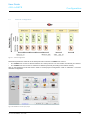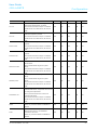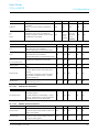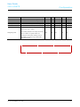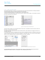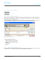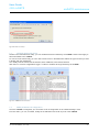
1
1473-1-8485│ 26.03.2014 User Guide ABB doGATE geb ic h User Guide ABB doGATE 1 2 3 4 5 6 Introduction Introduction .............................................................................................................................................................. 4 Used Symbols .......................................................................................................................................................... 4 Main Characteristics ................................................................................................................................................ 5 3.1 Presentation ............................................................................................................................................ 5 3.2 Embedded Automation............................................................................................................................ 5 3.3 BACnet Monitoring .................................................................................................................................. 5 3.4 OPC Monitoring ...................................................................................................................................... 5 3.5 oBIX Monitoring ...................................................................................................................................... 5 Getting started ......................................................................................................................................................... 6 4.1 Environmental characteristics ................................................................................................................. 6 4.2 Mechanical characteristics ...................................................................................................................... 6 4.3 Electrical characteristics.......................................................................................................................... 6 4.4 Electrical wiring ....................................................................................................................................... 7 4.4.1 Power Supply .......................................................................................................................................... 7 4.4.2 Networks ................................................................................................................................................. 7 Software Installation ................................................................................................................................................. 8 5.1 Install doMOOV (Server for PC, Dashboard, OPC server) on a PC ........................................................ 8 5.2 Dashboard Use ....................................................................................................................................... 8 Configuration.......................................................................................................................................................... 10 6.1 Supported Fields Protocols ................................................................................................................... 10 6.1.1 Modbus over RS232 & RS485 .............................................................................................................. 10 6.1.2 Modbus over IP ..................................................................................................................................... 10 6.1.3 M-Bus over RS232 ................................................................................................................................ 10 6.1.4 BACnet over IP ..................................................................................................................................... 10 6.1.5 LonWorks over IP.................................................................................................................................. 10 6.1.6 KNX over IP .......................................................................................................................................... 10 6.1.7 OpenWebNet ........................................................................................................................................ 10 6.2 doGATE Configuration with the dashboard ........................................................................................... 11 6.2.1 Create a site .......................................................................................................................................... 11 6.2.2 Create a DataServer ............................................................................................................................. 12 6.3 Networks Configuration ......................................................................................................................... 14 6.3.1 Selection of the port to create a Network .............................................................................................. 15 6.3.2 Create a Network Organization ............................................................................................................. 15 6.3.2.1 LonWorks Organization......................................................................................................................... 16 6.3.2.2 KNX Organisation ................................................................................................................................. 20 6.3.2.3 BACnet Organization ............................................................................................................................ 22 6.3.2.4 Modbus organization ............................................................................................................................. 24 6.3.3 Communication checking with devices on the field networks ................................................................ 25 6.4 Automation Functions ........................................................................................................................... 26 6.4.1 The Automation Center ......................................................................................................................... 26 6.4.1.1 Automation items Definition .................................................................................................................. 26 6.4.1.2 Filters and Folders ................................................................................................................................ 34 6.4.1.3 Multiple selection and Copy/Paste on Automation items....................................................................... 35 6.4.2 The Memory Driver ............................................................................................................................... 35 6.4.2.1 Creating datapoints ............................................................................................................................... 35 6.4.2.2 Advances Options ................................................................................................................................. 36 6.4.2.3 points Behaviour ................................................................................................................................... 36 6.4.3 Actions Configuration ............................................................................................................................ 36 6.4.3.1 Configure a datapoint Write .................................................................................................................. 37 6.4.3.2 Configure e-mail sending ...................................................................................................................... 37 6.4.3.3 Configure a actions combination ........................................................................................................... 38 6.4.4 Schedulers Configuration ...................................................................................................................... 38 6.4.4.1 Scheduler Basic Operation ................................................................................................................... 38 User Guide ABB doGATE | 1473-1-8485 —2— User Guide ABB doGATE 7 Introduction 6.4.4.2 Define a Weekly Schedule .................................................................................................................... 39 6.4.4.3 Define exceptions and calendars .......................................................................................................... 40 6.4.4.4 Schedulers advanced settings .............................................................................................................. 41 6.4.4.5 Map schedulers on BACnet .................................................................................................................. 42 6.4.5 Gateways configuration......................................................................................................................... 42 6.4.5.1 Gateway basic operation....................................................................................................................... 42 6.4.5.2 Gateway definition................................................................................................................................. 43 6.4.6 Alarms configuration ............................................................................................................................. 45 6.4.6.1 Alarms basic operation.......................................................................................................................... 45 6.4.6.2 Alarm definition ..................................................................................................................................... 45 6.4.6.3 Map alarms on BACnet ......................................................................................................................... 46 6.4.7 Trends configuration ............................................................................................................................. 46 6.4.7.1 Trends basic operation.......................................................................................................................... 46 6.4.7.2 Trend definition ..................................................................................................................................... 46 6.4.7.3 Map trends on BACnet .......................................................................................................................... 47 6.5 BACnet server configuration ................................................................................................................. 48 6.5.1 BACnet server basic operation ............................................................................................................. 48 6.5.2 Object definition on the BACnet server ................................................................................................. 48 6.5.3 Advanced parameters of the BACnet server ......................................................................................... 49 6.5.4 BACnet server deletion ......................................................................................................................... 50 6.6 Advanced Settings of the automation center......................................................................................... 51 6.6.1.1 CSV Import / export............................................................................................................................... 51 6.6.1.2 EDE Export ........................................................................................................................................... 51 6.6.1.3 Configurations cleaning......................................................................................................................... 52 6.7 OPC server Configuration ..................................................................................................................... 52 6.7.1 Avalibility in the OPC Server ................................................................................................................. 52 6.7.2 Connecting a client OPC to the OPC server ......................................................................................... 53 6.8 oBIX server configuration ...................................................................................................................... 54 6.8.1 Activate the oBIX server........................................................................................................................ 54 6.8.2 Configure the oBIX server ..................................................................................................................... 55 doGATE maintenance ........................................................................................................................................... 56 7.1 project backup ....................................................................................................................................... 56 7.2 Restore a Backup.................................................................................................................................. 56 7.3 Generate functioning traces .................................................................................................................. 57 7.4 Modify doGATE’s IP configuration ........................................................................................................ 57 7.5 Stop/Start all doGATE’s functionalities.................................................................................................. 58 7.6 Licenses ................................................................................................................................................ 58 User Guide ABB doGATE | 1473-1-8485 —3— User Guide ABB doGATE 1 Introduction Introduction Welcome in the doGATE configuration documentation. You will find in this document the hardware and configuration procedures for doGATE. For more information on a specific configuration, please refer to the table of contents. 2 Used Symbols Explanation of the different symbols used in this documentation. NOTE Content demanding a specific attention. Detailed Explanation. CAUTION! P ro d u c t d a m a g e ! Report an electrical danger or a warning on a potential electrical damage to the device. User Guide ABB doGATE | 1473-1-8485 —4— User Guide ABB doGATE 3 Main Characteristics Main Characteristics The doGATE is a hardware device that can be used alone or in clusters to federate several BMS protocols over IP. 3.1 P re s e n ta tio n The doGATE embeds doMOOV software. The device is optimized for a fast commissioning. The dual IP interface ensures independence of field and monitoring networks. Serial interfaces, often absent of traditional computers, are available to configure M-Bus or Modbus networks. 3.2 Em b e d d e d Au to m a tio n The doGATE embeds different engines that can provide gateways between protocols, schedulers, alarms and trends. 3.3 BACn e t Mo n ito rin g The doGATE embeds a BACnet server that can map field information from any supported protocol to BACnet objects and properties. It also includes schedulers, trends and alarms. 3.4 OP C Mo n ito rin g By installing doMOOV OPC server on a SCADA PC, you have an OPC server that can communicate with one or several doGATE and thus spread data monitoring between different devices. 3.5 o BIX Mo n ito rin g The doGATE embeds an oBIX server allowing to monitor data from the field buses by *.xml files exchanges. This server also includes schedulers, trends and alarms functionalities. User Guide ABB doGATE | 1473-1-8485 —5— User Guide ABB doGATE Getting started 4 Getting started 4.1 En viro n m e n ta l c h a ra c te ris tic s P a ra m e te r Va lu e -20°C to +70°C Working T° ambient temp. with ventilation Storage T° -40°C to +85°C Relative humidity 10 to 95% at 40°C without condensation Vibrations 1.5 g.ms from 5 to 500Hz Resistance to shock 20G (11ms), Stop 60G 4.2 Me c h a n ic a l c h a ra c te ris tic s P a ra m e te r Va lu e Material Aluminium alloy Mounting On table, vertical or horizontal DIN rail Weight 2kG Dimensions 252 x 199 x 33 mm Power 20G (11ms), Stop 60G 4.3 Ele c tric a l c h a ra c te ris tic s P a ra m e te r Va lu e Input voltage 10VDC to 28 VDC Max. power 25W Processor Intel Atom N270 1.6GHz Memory 1Go RAM HDD* 250 Go Compact Flash* 4 Go * According to the chosen option User Guide ABB doGATE | 1473-1-8485 —6— User Guide ABB doGATE Getting started 4.4 Ele c tric a l w irin g 4.4.1 P o w e r S u p p ly Two types of power supplies are available as options: • A table power supply • A DIN rail power supply CAUTION! P ro d u c t d a m a g e ! It is recommended to use an uninterruptible power supply in order to avoid malfunction or device deterioration. 4.4.2 Ne two rks P o rt Mé d ia P ro to c o le s u p p o rté COM1 RS232 M-Bus COM2 RS485 M-Bus, ModBus COM3 RS485 M-Bus, ModBus USB / Currently None LAN1 Ethernet BACnet, ModBus IP, KNX IP, LonWorks IP LAN2 Ethernet BACnet, ModBus IP, KNX IP, LonWorks IP User Guide ABB doGATE | 1473-1-8485 —7— User Guide ABB doGATE 5 Software Installation Software Installation Are depicted in the following sections, how to install the software for configuring a doGATE and accessing to its functionalities. 5.1 In s ta ll d o MOOV (S e rve r fo r P C, Da s h b o a rd , OP C s e rve r) o n a P C Since the 1.4.x.x version, the way how the installation is done has been reviewed. There is one setup per application. Therefore, you have to pick up from the CD provided the desired doMOOV setup file. These installations are able to coexist on the same computer. However, the most complete one, the doMOOV Server for PC includes all of them. Figure 1: Access to the configuration Dashboard Tool The installation of doMOOV Server for PC installs all the functionalities on the computer. There are the 3 Windows Services enabling the doMOOV functioning (doMOOV Server, doMOOV Updater and doMOOV http Server). In addition of letting you getting connected to a doGATE, this installation also allows to have doMOOV functioning on the local computer. For simplicity and backward compatibility reasons, the light ”Dashboards” of each version can be installed. They permit to get connected to the doGATE running older version of doMOOV. 5.2 Da s h b o a rd Us e The dashboard allows to create a site organisation with multiple doGATEs as well as the organization of “Network”, “Scheduler”, “Alarm” and “Gateway” of each doGATE seperately. User Guide ABB doGATE | 1473-1-8485 —8— User Guide ABB doGATE Software Installation Figure 2: General Site Architecture User Guide ABB doGATE | 1473-1-8485 —9— User Guide ABB doGATE 6 Configuration Configuration Prepare a doGATE for monitoring field networks and perform automation functions. On one given IP port can cohabit several protocols without any problem. Each of those protocols being individually encapsulated, it is for instance possible to bring up data from a KNX, a LonWorks and a Modbus networks on one IP port. Then, this data can be accessible by a SCADA system over BACnet on the same IP port. 6.1 S u p p o rte d Fie ld s P ro to c o ls 6.1.1 Mo d b u s o ve r RS 232 & RS 485 RTU or ASCII modes are available in Master mode. 6.1.2 Mo d b u s o ve r IP On the standard communication port 502, doGATE will read and write data on Modbus devices in Master mode. 6.1.3 M-Bu s o ve r RS 232 M-Bus protocol is used to collect data from counters in fields of energy, water … It is used with a converter to provide energy to remote counters. Several interfaces exist depending on the number of sensors to connect. 6.1.4 BACn e t o ve r IP BACnet protocol is used by many field automation devices. It is also used as a unifying protocol in SCADA systems. 6.1.5 Lo n Wo rks o ve r IP LonWorks protocol is used by field devices in several application fields of BMS. It is possible, through routers (L-IP for instance), to transfer information over the IP network coming from the field devices. 6.1.6 KNX o ve r IP KNX protocol is used by field devices in several application fields of BMS. It is possible, through routers, to transfer over the IP network information coming from the field devices. 6.1.7 Op e n We b Ne t The OpenWebNet protocole is protocol established by the Legrand company. User Guide ABB doGATE | 1473-1-8485 — 10 — User Guide ABB doGATE 6.2 Configuration d o GATE Co n fig u ra tio n with th e d a s h b o a rd NOTE To configure the doGATE, you must be connected on the IP port 1 (LAN1). Its default IP Address is 192.168.1.254. 6.2.1 Cre a te a s ite In order to configure a doGATE with the dashboard, you first need to create a site in the dashboard. A site is a project gathering the configurations of one or several doGATE. To create a site, launch the dashboard. Figure 3: Dashboard Opened for the first configuration Open the “Sites Manager” and click on “Add new…”. Figure 4: Sites Manager User Guide ABB doGATE | 1473-1-8485 — 11 — User Guide ABB doGATE Configuration Enter a name for the site and validate. The site is created. Open the site using the Sites Manager; the name of the currently opened site appears at the top of the left menu. Figure 5: Dashboard with an opened site 6.2.2 Cre a te a Da ta S e rve r The doGATE devices are referenced in the site as “DataServers”. To add a doGATE to the site, you must add and configure the corresponding DataServer. Click on “Add DataServer” in order to add a doGATE to the site. Select then Station type “doGATE”. Enter a name for the doGATE and its IP address. You can use the button “First time configuration …” to simplify the discovery of new doGATE on the network. The default IP address of a doGATE is 192.168.1.254 Figure 6: doGATE DataServer Configuration This IP Address is, afterwards, changeable from the main configuration window. To do so, click on the “Station Settings” button on the Dashboard to modify it at your convenience. User Guide ABB doGATE | 1473-1-8485 — 12 — User Guide ABB doGATE Configuration Once modified, the LAN 1 port’s IP Address is automatically modified in the connection address used by the Dahsboard to get connected to the doGATE. Figure 7: doGATE’s IP adresses Configuration NOTE Please note that for using simultaneously LAN1 & LAN2, the both ports have to be in different IP Subnets. If you just use one IP Subnet, just use the LAN1 port. Once the DataServer created, this one appears in the left menu. You can click on it to access doGATE’s functionalities configuration. Figure 8: DataServer doGATE Added to the site User Guide ABB doGATE | 1473-1-8485 — 13 — User Guide ABB doGATE 6.3 Configuration Ne two rks Co n fig u ra tio n Figure 9: networks Organisation Networks represent the channels of the field protocols on which the doGATE can connect. • The doGATE can connect to several channels of a same protocol. You must create one network per channel. • The doGATE can also connect to channels of different protocols (according to the license chosen). Click on the DataServer in the left menu in order to access project’s configuration. Click on “Networks” to access networks configuration. Figure 10: DataServer with an open project User Guide ABB doGATE | 1473-1-8485 — 14 — User Guide ABB doGATE Configuration 6.3.1 S e le c tio n o f th e p o rt to c re a te a Ne tw o rk You have to select the desired port in the top menu in order to create a network. Protocols available depend on the selected port. BACn e t IP Lo n Wo rks IP KNX Mo d b u s IP Mo d b u s S e ria l IP M-Bu s S e ria l IP 1 X X X X IP 2 X X X X Serial 1 X Serial 2 X Serial 3 X X Figure 11: Network Configuration menu Once the port selected, click on “Add network” and choose the protocol. Validate in order to create the network. 6.3.2 Cre a te a Ne tw o rk Org a n iza tio n Defining a network organization allows to visualize the list of devices and datapoints available on the channel. It represents the hierarchical view of information of this channel. It is not mandatory to define a network organization (unless you use doMOOV OPC server), meanwhile in order to ease doGATE’s functionalities configuration, it is better to define an organization for each network. There are several methods available to create a network organization. The available methods depend on the protocol chosen for the network. • BACnet: Network scan, EDE file import and CSV file import • LonWorks: LNS database import, CSV file import User Guide ABB doGATE | 1473-1-8485 — 15 — User Guide ABB doGATE • • • • Configuration KNX: ESF file import (generated by ETS), CV file import Modbus: CSV file import M-Bus: CSV file import Open Web Net: MHZ file import, CSV file import Figure 12: Example of Modbus network organization created from a CSV file 6.3.2.1 Lo n Wo rks Org a n iza tio n A LonWorks network can be generated thanks to a LNS database import or a *.csv file import. This network is configurable only on the IP ports. Therefore, a LonWorks network can only be accessed through an IP router. The easiest and quickest way for generating this network organization is to import a LNS database. To do so, the computer on which the Dashboard is currently running needs to have the LNS server installed and project registered within. If this is the case, there is just the “Import a LNS database …” button to press and select in the appearing dropdown menu the desired database: Figure 13: Definition of a LonWorks organization in the menu “Network Organization” User Guide ABB doGATE | 1473-1-8485 — 16 — User Guide ABB doGATE Configuration Figure 14: Selection of mode during the creation of the network organization All the nodes, their addresses and their variables will therefore be imported in the doGATE. Once imported, this database can also be exported in a CSV file. To do so, the “Export…” button is present in the same window where the import choice is done. When an organization has been defined, it is possible to export it thanks to this button: Figure 15: Export of the network organization 6.3.2.1.1 Da ta b a s e Filte rin g It is possible to realize filtering in order to import only one part of the selected database. The filters can be applied at the following levels: • Device Template • Subsystems • Nodes • LonMark Objects • Variables The defined filter will import only the datapoints which match this given filter. For instance, if in the subsystem part, is applied the filter “ *lighting* “, then, all the nodes belonging to a subsystem having the word “ *lighting* “ in their names, will be imported. User Guide ABB doGATE | 1473-1-8485 — 17 — User Guide ABB doGATE Configuration Figure 16: organization filtering 6.3.2.1.2 d o GATE : Ad d re s s in g & De vic e Te m p la te It is possible to declare the doGATE directly in the LNS database. The created node does not need to be commissioned (and will therefore not consume any credit in the LNS server used is in the Turbo Edition version). This permits to define exactly the Subnet/Node address that the doGATE will use in the LonWorks network. The *.XIF file can be found at the following path: C:\Program Files (x86)\Newron System\doMOOV\xifs In the case where the XIF file has not been imported in the LNS database, it is still possible to manually define the affected Subnet/Node address: Figure 17: doGATE Addressing The defined Subnet/Node address has to be: • In concordance with the LNS database imported. The doGATE being only over IP, the declared Subnet has to correspond to the IP Subnet number of the LNs database. This is important for the routing tables. • Unique in the base. Indeed, there cannot be two devices having exactly the same Subnet/Node address within a given LNS database. User Guide ABB doGATE | 1473-1-8485 — 18 — User Guide ABB doGATE Configuration 6.3.2.1.3 Co n fig u ra tio n S e rve r d e fin itio n As explained before, the doGATE can only access to the network through an IP router. To one given LNS database, corresponds only one router which is Configuration Server. This equipment knows what are the IP devices which will likely communicate with the network. This is also from the Configuration Server that the doGATE will obtain the routing tables from the entire LNS database in order to talk to the right device to get data from the network. The IP address of this Configuration Server has therefore to be filled in the LonWorks Network parameters: Figure 18: Configuration Server’s address definition The communication ports used between the Configuration Server and the doGATE also have to be defined. The default ones are 1628 (Input) / 1629 (Output). In case of change of those settings, they have to be changed as well in this configuration. User Guide ABB doGATE | 1473-1-8485 — 19 — User Guide ABB doGATE Configuration 6.3.2.2 KNX Org a n is a tio n The KNX organization import can be done through either an ESF file or a CSV file. The easiest and still the quickest way of working is to use the ESF file. This one is directly exported from the ETS tool used for the KNX network configuration. It details all the KNX Group Addresses which the doGATE will be able to interact with. Their types is an important data to have the correct reading and writing format of these points. Unfortunately, the ETS export does not fill automatically all the data types. An additional manual work is required to assign to each Group Address its correct format. 6.3.2.2.1 Typ a g e d e s a d re s s e s d e Gro u p e KNX In a normal ESF file import, each entry has to be manually modified to set the correct type when they are not automatically filled. In order to simplify and accelerate this import, there is a CSV file named “ESFImportAutomaticConversion.csv”. It is located in the path “C:\Program Files (x86)\Newron System\doMOOV\Bin”. It can be modified thanks to a simple text editor (Notepad, etc.) to have an automatic types definition according to the rules specified within. In the header of this file, some examples of functioning are present: EIS 5;Temperature;;DPT_Value_Temp EIS 4;;;DPT_Date EIS 5;Temperature;;DPT_Value_Temp Uncertain;;Room3Temp;DPT_Value_Temp In this last example : Uncertain;;Room3Temp;DPT_Value_Temp All the Group Addresses having a type “Uncertain" and containing the word "Room3Temp” in their names, will automatically get the “DPT_Value_Temp” type. In a general way, the formula is: Type;Subtype;GroupNameSearch;CatalogTypeToUse Thereby, if there are X Group Addresses named on the same way, with a given type, you can change and type them automatically in one time. 6.3.2.2.2 Da ta u p d a te o n e ve n t The KNX network is not the fastest network ever, in terms of speed of transmission. Over a Twisted Pair wire, the data transit at a speed of 9600 Bauds/second. Therefore, if there is a lot a traffic on the bus, some information may take up to several minutes to be brought up. However, the KNX protocol supports the data change on event which permits to lighten this communication load. This feature is called COV (Change On Value) or Event To configure this feature on the Group Addresses read by the doGATE, there are two solutions. They are detailed in the two following paragraphs. User Guide ABB doGATE | 1473-1-8485 — 20 — User Guide ABB doGATE 6.3.2.2.2.1 Configuration Through the network organization Export in a CSV file the defined network organization: Figure 19: Export in a CSV file the network organization Then, this CSV file has to be edited. On the datapoints, after their types, the /cov or /event parameter has to be added: 3;@My_Group_Address_Name;15;16384 0;@CDPT_Bool_Control/cov;;8;3;int; Once the edition is finished, the modified CSV file has to be reimported to rebuild the organization and having the changes taken into account. 6.3.2.2.2.2 Through the automation center In the Automation Center, there is an option to export in CSV the configuration done of the automation items. Figure 20: Configuration export of the automation center in CSV In their addresses, the /cov or /event parameter has to be added. The addresses are built according to the following syntax: <Active>;<Section>;<Address>/cov;<Frequency>;<Deadband>;<Folder>;<Name> Or, in a more explicit example: X;ID;@Nknx@XLevel1@XMy_Group_Address_Name@CDPT_Bool_Control/cov;1000 In this last example, the polling time (the Frequency parameter) has no longer any influence in a field point of view. It has still to be defined but the datapoints updates will only be brought up when their values change. From a SCADA point of view, this polling time corresponds to the update time of the BACnet server (in case of the data is available over the doGATE’s BACnet server). Once this has been modified, the new CSV file has to be reimported. This can be done through the User Guide ABB doGATE | 1473-1-8485 icon. — 21 — User Guide ABB doGATE Configuration NOTE If a given Group Address is declared two times, one with and the other without /cov, then it has no benefit. Indeed, the point will be read at a cyclic time over the network and will therefore induce communication. NOTE Despite the /cov parameter defined, the Group Addresses will still be read once when initializing the communication and have one value. If you do not wish to initialize them, the datapoints have to be declared with “/cov/noinit”. 6.3.2.2.2.3 Writing point Particularity By definition, a writing point is not a reading point. Consequently, its state does not change automatically and therefore it does not send update over the KNX network. In order to have a feedback of the writing points, the “Transmit” flag has to be activated in the ETS database (the KNX network configuration tool). However, it appears that some writing points do not support the COV feature, despite the “Transmit” flag activated. This is characterized by the fact of sending a writing but no update is received, the datapoint has no value. Nevertheless, the datapoint has well received the writing and its state has changed as wanted. If the device accepts it, when writing, the value will change (feedback) and this proves the good reception of the writing command. In a general way, for the devices accepting it (sensors, feedbacks …), the COV feature is highly recommended. It is possible to have an organization where the COV feature is enabled on some datapoints and not on others (use of the cyclic polling). 6.3.2.2.3 De vic e Ab s e n t En g in e Unlike the others protocols, the KNX way of functioning does not permit the use of the device absent engine which is integrated in doMOOV. This engine permits to no longer solicit a device when this one does not respond positively after several connection tries. Thus, this lightens the communication by avoiding to constantly request an absent device. The KNX protocol, by its functioning based on Group Addresses, may mutualize several devices in one given Group Address. Thus, we cannot consider the entire Group Address as absent if one of the composing device is absent. The COV feature, explained above, permit to get rid of this constraint. 6.3.2.3 BACn e t Org a n iza tio n The BACnet protocol takes place at two different levels: Field: For the communication with devices, either in BACnet/IP or in BACnet MS/TP trough an IP router. Management: For the communication with a SCADA system. User Guide ABB doGATE | 1473-1-8485 — 22 — User Guide ABB doGATE Configuration 6.3.2.3.1 At th e fie ld le ve l In the case of a communication with field devices, the easiest way to build up the network organization is to use the network scan. It permits to scan part of all the network, in order to bring back up information about the discovered devices. Will then be added to the network organization, all the BACnet devices discovered and their respective DeviceIDs, the different objects composing them, identified by their instances. This network organization can also be built from an EDE file. This file is standardized by the BACnet protocol and it permits to define the different devices and their objects. Finally, it is also possible to work with a CSV file. 6.3.2.3.2 At th e m a n a g e m e n t le ve l Concerning the management level, communication between the doGATE and a SCADA system, there is no network organization to build up. Enabling the BACnet server is enough, for being able to map datapoints on it (from either a BACnet field network or any other field protocol). Figure 21: BACnet server activation User Guide ABB doGATE | 1473-1-8485 — 23 — User Guide ABB doGATE Configuration 6.3.2.4 Mo d b u s o rg a n iza tio n The Modbus protocol has not standard tool dedicated to its construction. So, there is the need to manually declare the Modbus organization you want to work with. The ModBus devices have each a unique participant number on the network and the datapoints values are stored in registers. You need to specify in this CSV file: • Participant number for this device • Type of the read value (Coil, Register, …) • Its register address • Its length Ca ta lo g Id e n tifie r De s c rip tio n @Cbit Boolean value @Cshort Integer (16-bits) @Cshortle Integer (Little-Endian) (16-bits) @Cshortbe Integer (Big-Endian) (16-bits) @Cushort Unsigned Integer (16-bits) @Cushortle Unsigned Integer (Little-Endian) (16-bits) @Cushortbe Unsigned Integer (big-Endian) (16-bits) @Cint Integer (32-bits) @Cintle Integer (Little-Endian) (32-bits) @Cintbe Integer (Big-Endian) (32-bits) @Cuint Unsigned Integer (32-bits) @Cuintle Unsigned Integer (Little-Endian) (32-bits) @Cuintbe Unsigned Integer (Big-Endian) (32-bits) @Cfloat Float @Cfloatbe Float (Big-Endian) @Csle Integer (Little-Endian) (16-bits) @Csbe Integer (Big-Endian) (16-bits) @Cusle) Unsigned Integer (little-Endian) (16-bits @Cusbe Unsigned Integer (big-Endian) (16-bits) @Cile Integer (Little-Endian) (32-bits) @Cibe Integer (Big-Endian) (32-bits) @Cuile Unsigned Integer (Little-Endian) (32-bits) @Cuibe Unsigned Integer (Big-Endian) (32-bits) @Cuilesw Unsigned Integer (Little-Endian word-swapped) (32-bits) @Cfle Float (Little-Endian) @Cfbe Float (Big-Endian) Here is an example of a CSV file for the network organization description concerning a Modbus TCP network: User Guide ABB doGATE | 1473-1-8485 — 24 — User Guide ABB doGATE Configuration VERSION=1 NAME=Modbus_Organization TRANSPORT=ModBusIp 1;@XDevice Floor 01;@D169.254.0.10:502|tcp|1;8 2;@XActive energy total counter;@Preg1038;32 0;@Cdefault;;8;3;; 2;@XFrequency;@Preg1022;32 0;@Cdefault;;8;3;; 2;@XLine 1 to line 2 voltage;@Preg1008;32 0;@Cdefault;;8;3;; 2;@XPhase 1 current;@Preg1000;32 0;@Cdefault;;8;3;; 2;@XTotal active power;@Preg1020;32 0;@Cdefault;;8;3;; Here the example of a CSV file for Modbus RTU: VERSION=1 NAME=Modbus_Organization TRANSPORT=ModBusRTU 1;@XDevice Floor 01;@D25|RTU;8 2;@XActive energy total counter;@Preg1038;32 0;@Cdefault;;8;3;; 2;@XFrequency;@Preg1022;32 0;@Cdefault;;8;3;; 2;@XLine 1 to line 2 voltage;@Preg1008;32 0;@Cdefault;;8;3;; 2;@XPhase 1 current;@Preg1000;32 0;@Cdefault;;8;3;; 2;@XTotal active power;@Preg1020;32 0;@Cdefault;;8;3;; Where : @X: Branch name @D: Device Identification @P: Datapoint type Identification @C: Catalog Identifier 6.3.3 Co m m u n ic a tio n c h e c kin g with d e vic e s o n th e fie ld n e tw o rks Once your network is created, you can check out the good communication between the doGATE and field devices present on the different networks the doGATE is connected to. To do so, in the Dashboard, click on the Monitoring icon: Choose from the left tree view in the available network organizations, the values you want to write or read. User Guide ABB doGATE | 1473-1-8485 — 25 — User Guide ABB doGATE Configuration Double click on a datapoint to add it to the list of values monitored. If you have not defined a network organization, you can add the address of the datapoint in the Manual datapoint address field. If you click on the arrow at the bottom right of this field, a wizard will allow you to define addresses of values to monitor. Figure 22: Reading values from a modbus network The quality field reports the communication quality for the added points. It may report a communication failure with the network. You can also modify the reading frequency of the value, multiply the value by a factor or add an offset, or save a list of items to monitor for a later use. 6.4 Au to m a tio n Fu n c tio n s 6.4.1 Th e Au to m a tio n Ce n te r The Automation Center is an interface used to configure automation functions of the doGATE. It is used to define Automation items, which are the values used by automation functions to interact with the networks. 6.4.1.1 Au to m a tio n ite m s De fin itio n Automation items are values on which act automation functions. It is MANDATORY to define Automation items if you want to configure automation functions. To create Automation items, you must go to the left part of the interface. User Guide ABB doGATE | 1473-1-8485 — 26 — User Guide ABB doGATE Configuration Through the menu, there are two ways of defining Automation items: • With network organizations previously defined • With address wizard Figure 23: Left menu of the Automation Center 6.4.1.1.1 Th ro u g h th e Ne tw o rk Org a n iza tio n In the “Organization” part, you can browse the network organizations and double click on a datapoint in order to add it as an Automation item. You can also add automatically datapoints of a device or a network; you must select the device or the network, click on the double arrow at the bottom right of the tree view. A menu will propose to create filters on datapoints you want add as Automation items. Figure 24: Filter for automatic adding You can combine several filters to create Automation items. User Guide ABB doGATE | 1473-1-8485 — 27 — User Guide ABB doGATE Configuration 6.4.1.1.2 Ad d in g Mu lti-fie ld s va lu e s The automation items also can be a reference to multi-fields variables. To be able to add a multi-fields variable, you first need to selection the desired point, through one of its fields to get its entire address written in the form located below the organization. Once done, the part of the address referring to the field has to be deleted to just let the variable’s address: Figure 25: Adding a multi-fields V ARI ABLE 6.4.1.1.2.1 Limitations of the multi-fields variables Being composed of different fields, those variables will not behave strictly in the same way than the “mono-field” variables do. Indeed, it is not possible to: • Define trending • Map them on the BACnet server 6.4.1.1.2.2 Multi-fields variables writing The writing of these variables is also specific to their format. If, for instance, you wish to write this variable in the monitoring, here are the ways to proceed: Writing all the fields : A space has to be placed between each field. These fields will therefore be written in the same way as they have been referenced at the field level. For instance: 01020661 This is the result of the writing : Field 1 = 0 Field 2 = 1 Field 3 = 0 Field 4 = 2 Field 5 = 0 Field 6 = 6 Field 7 = 6 Field 8 = 1 If the variable is composed of 15 fields, then, in this example, only the 8 first ones will be written. The 7 following ones will keep their values. User Guide ABB doGATE | 1473-1-8485 — 28 — User Guide ABB doGATE Configuration Writing some fields by avoiding to write the non-desired ones. It is possible to write only some fields and therefore to let the others at their current values. For instance: Bit1=0 Bit6=2 Bit9=2 Bit15=1 This is the result of the writing: Field 1 = 0 Field Field 3 = 0 Field Field 5 = 0 Field Field 7 = 2 (Bit6) Field 8 = 0 Field 9 = 0 Field Field 11 = 0 Field Field 13 = 0 Field Field 15 = 0 Field 2 = 0 (Bit1) 4=0 6=0 10 12 14 16 = = = = 2 (Bit9) 0 0 1 (Bit15) 6.4.1.1.3 Th ro u g h th e Ad d re s s Wiza rd In the “Address Wizard” part, you have the possibility to add, as automation items, datapoints available over the network but possibly not imported by a network organization. There is a Wizard per activated protocol. Each of them permit to add Automation items according to their addresses, accordingly to each protocol. This Wizard helps you to create the datapoints’ addresses. Once the address and options filled, you can add the datapoint as automation item by clicking on the double arrow located in right bottom corner of the form containing the generated address. 6.4.1.1.4 Ad d itio n a l P a ra m e te rs It is possible to define functions or specific behaviors to the variables added in the “automation center”. Here is the detail of these parameters, which have to be added at the end of the point’s address. The parameters can be cumulated. 6.4.1.1.4.1 Multi-Protocols Parameters Op tio n /raw De s c rip tio n Monitor the raw value. In this case Catalog identifier may be omitted. /allfields Monitor all fields of the value. /af Equivalent to @Fall. /enumasstring /eas /enumasinteger /eai BACn e t KNX Lo n Wo rks MBu s Mo d b u s OK OK OK OK OK OK OK OK OK OK OK OK OK OK OK OK OK OK OK OK OK OK OK OK OK OK OK OK OK OK Enumeration are used formatted with string value. If absent enumeration are used as integer. Enumeration are used formatted with integer value. If absent enumeration are used as integer. Fields name are present in the value when /fieldnamealways /fna string type is used. If absent field names are not displayed. If present, the value will look like: field1=1 field2=2 /fieldnameifmultifield /fnm Fields name are present in the value when string type is used and if more than one field is present in the value. User Guide ABB doGATE | 1473-1-8485 — 29 — User Guide ABB doGATE Op tio n Configuration De s c rip tio n BACn e t KNX Lo n Wo rks MBu s Mo d b u s OK OK OK OK OK OK OK OK OK OK OK OK OK OK OK OK OK OK OK OK OK OK OK OK OK OK OK OK OK OK OK OK OK OK OK OK OK OK NO NO OK OK OK OK OK OK OK OK OK OK OK OK OK OK OK OK OK OK OK OK When fields name are visible (/fna or /fnm), the /pathasfieldname /pfn field name is the full path of the field in the structure. By default field name is only the name of the field, not the path. Raw value in a string is formatted with decimal values. By default raw value in a string is formatted as /rawdecimal /rwd hexadecimal. If present value will look like : ‘160 161 162’ If not present value will look like : ‘A0 A1 A2’ Do not round double. By default double are automatically round with 2 /donotround /dnr digits max after the decimal separator. If present value will look like : 34,098340830498 If not present value will look like : 34,10 Indicates the value will be read only one time at /readonce startup, and no more polled. Useful for value that never change (EEPROM values for instance). /writeonly Indicates the value will never be read and only /wo Write operation are permitted. Do not read the persistent value only one time /persistennotonce but continuously. /pno Note that only datapoint from database can be considered as persistent. /readonly Indicates that no Write operations are allowed /ro on this value. /noinit Indicates that no Read operations are done on /noi start (useful for the COV DataPoint) Dead-band. /dbd=value This is the minimum value change before sending event to client Factor to apply to the value. /factor=value The value is a double. Supported only for single field with a numeric value. Offset to apply to the value. /offset=value The value is a double. Supported only for single field with a numeric value. /groupitems=value Maximum time between two items to be polled together on a device. User Guide ABB doGATE | 1473-1-8485 — 30 — User Guide ABB doGATE Op tio n Configuration De s c rip tio n BACn e t KNX Lo n Wo rks MBu s Mo d b u s OK OK OK OK OK OK OK OK OK OK OK OK OK OK OK OK OK OK OK OK OK OK OK OK OK OK OK OK OK OK OK OK OK OK OK OK OK OK OK OK OK OK OK NO NO If 1, read multiple is active. The engine tries to read several items together if possible. /rm=1/0 Value stored at the device scope. If 2 different values are set for a same device, last value is used. If 1, write multiple is active. The engine tries to write items together if possible. /wm=1/0 Value stored at the device scope. If 2 different values are set for a same device, last value is used. Maximum number of bytes or items read together. /maxrm=value Value stored at the device scope. If 2 different values are set for a same device, last value is used. Maximum number of bytes or items write together. /maxwm=value Value stored at the device scope. If 2 different values are set for a same device, last value is used. Number of consecutive errors to consider the device absent. Zero to disable absent engine for specific /absecount=value device. Value stored at the device scope. If 2 different values are set for a same device, last value is used. Frequency in seconds to verify an absent device. Zero to disable absent engine for specific /absefreq=value device. Value stored at the device scope. If 2 different values are set for a same device, last value is used. If 1, writing a value on a device that is considered as absent, will generate an error and no writing will be performed. /writeabsent=1/0 Zero to perform the write even if device is considered as absent. Value stored at the device scope. If 2 different values are set for a same device, last value is used. Indicates we want to monitor a device status. /status Works only on device address not DataPoint address. Item used to reset a device. Write the item value to 1 to send Reset /reset command to the device. Works only on device address not DataPoint address. User Guide ABB doGATE | 1473-1-8485 — 31 — User Guide ABB doGATE Op tio n Configuration De s c rip tio n BACn e t KNX Lo n Wo rks MBu s Mo d b u s OK OK OK OK OK NO NO Indicates it will monitor the device presence on the network. /presence Works only on device address not DataPoint address. /cov Indicates the engine listen to the DataPoint or message coming from network, and do not read /event the DataPoint on the network. OK OK (only for Group Address) OK (only for NV bound to the doGATE) BACnet Specific Parameters Op tio n De s c rip tio n BACn e t KNX Lo n Wo rks MBu s Mo d b u s OK NO NO NO NO OK NO NO NO NO OK NO NO NO NO OK NO NO NO NO OK NO NO NO NO OK NO NO NO NO BACn e t KNX Lo n Wo rks MBu s Mo d b u s NO OK NO NO NO BACn e t KNX Lo n Wo rks MBu s Mo d b u s NO NO NO NO OK NO NO NO NO OK Indicates the Data Server must subscribe to COV notification for the DataPoint. /ccov This will subscribed to confirmed COV service Indicates the Data Server must subscribe to COV notification for the DataPoint. /ucov This will subscribed to unconfirmed COV service /cov_inc=value or Indicates COV dead-band for subscription. /cov_increment=value Indicates the priority to use when writing the /priority=value item. Time for the device to respond to services requests. Default value is 1000 milliseconds (1 second). /timeout=value For example, if a property is read on a device that is offline, it will take Timeout + (Timeout * Retries) milliseconds. Number of service requests retries to perform /retries=value 6.4.1.1.4.2 before returning an error. KNX Specific Parameters Op tio n De s c rip tio n Indicates the size of the window to read KNX parameters together. /intlvparams=value If 2 KNX parameters are separated by 1 byte in memory, a window size of 1 byte will make that the KNX parameters will be read together. 6.4.1.1.4.3 Op tio n Modbus Specific Parameters De s c rip tio n Interleave to read or write multiple coils. /intlvcoil=value This is the number of bits between 2 items to be read or write together. Interleave to read or write multiple registers. /intlvreg=value This is the number of bytes between 2 items to be read or written together. User Guide ABB doGATE | 1473-1-8485 — 32 — User Guide ABB doGATE Configuration Op tio n De s c rip tio n BACn e t KNX Lo n Wo rks MBu s Mo d b u s /maxrcoil=value Maximum number of coils read together. NO NO NO NO OK /maxwcoil=value Maximum number of coils written together. NO NO NO NO OK /maxrreg=value Maximum number of registers read together. NO NO NO NO OK /maxwreg=value Maximum number of registers written together. NO NO NO NO OK /iwr=value Ignore the content of the response to a write. NO NO NO NO OK NO NO NO NO OK Indicates the default values’ endianness with length longer than 1 register. /defregisbig=value If the catalog identifier is an integer 32 bits the value is coded on 2 register values, this property will indicate if the resulting value is calculated by encoding in big or little endian depending this flag. Once the Automation items are created, You can configure the Automation functions User Guide ABB doGATE | 1473-1-8485 — 33 — User Guide ABB doGATE Configuration 6.4.1.2 Filte rs a n d Fo ld e rs You can organize the automations by using folders. This way, you can, for instance, create a folder per device or per level. Then, you place the automation item of this device or this level in the corresponding folder. The folder is affected at Automation item creation. Therefore, it is required to create folders before Automation items. To create one or several Automation items in a folder, you must select the folder, and then create Automation items. When you select a folder, only items created in this folder will be visible in the grid. It is also possible to apply filters on display of the Automation items currently shown in the grid. Filters are available in the upper menu at the top of the window. Filters can be classified in two categories: • Filters on protocol : Automation items are displayed depending on the network they belong to : BACnet, KNX, LonWorks … • Filters on automation functions : Automation items are displayed depending on the automation functions currently configured for them: alarms, trends … Figure 26: Folders Organization Example User Guide ABB doGATE | 1473-1-8485 — 34 — User Guide ABB doGATE Configuration 6.4.1.3 Mu ltip le s e le c tio n a n d Co p y/P a s te o n Au to m a tio n ite m s For easier configuration of automation functions, it is possible to apply configurations on a selection of Automation items. You can select several Automation items in the grid and apply on all or part of the selection either a configuration remove or paste a previously copied configuration. The selection of several Automation Items can be bone through the selection of one given point and then by keeping Shift pressed on your keyboard and selecting another node. All the nodes between the both will be selected. Otherwise, it can also be done by a multiple selection using the CTRL + Click command. For configuration copy / paste, you can copy one configuration (for instance alarm) or select several configurations to copy (alarm + trend + …). The contents of the clipboard are displayed in the upper menu in the “Edit tools” menu. Figure 27: Content display of the copied configurations 6.4.2 Th e Me m o ry Drive r The doGATE natively offers a memory network, allowing you to define your own datapoints within the doGATE. These points can be either persistent or non-persistent. Note: a persistent point will keep the value you wrote on it, throughout the potential disconnections and power failures 6.4.2.1 Cre a tin g d a ta p o in ts To define datapoints within the memory driver, you have to use the “Address wizard” tool. This one is located in the “Automation Center”, on the second tab of the left panel. Then, potentially among other protocols, will be listed the Memory one: Figure 28: Points creation in the Memory Driver User Guide ABB doGATE | 1473-1-8485 — 35 — User Guide ABB doGATE Configuration In the form below will appear 3 different parameters to define the point(s) you wish to create: • The first one concerns its name. It has to be without space and dot. • The second one concerns if you want it to be persistent or not • The last one is its type. It could be either Real, Integer, Boolean or String 6.4.2.2 Ad va n c e s Op tio n s Below, you will find out an additional button leading you to further options: Figure 29: Options for Memory point creation In these others options, you can define if you want to round the float values, define a dead band before updating the value, a factor and an offset. You can also define whether you want to read the point only one time or not, and if the point is on read only access. 6.4.2.3 P o in ts Be h a vio u r The points you define within the memory driver will be different if: • Their types are different (even if called similarly) • One is persistent and another is not (even if called similarly) • Different names even with a similar configuration Then, the created points will be added and listed among the others automation items already defined. You will be able to interact with them exactly in the same way as you can do with datapoint from any other protocol. 6.4.3 Ac tio n s Co n fig u ra tio n Actions are instructions executed when an event is triggered in the weekly schedule or in an exception. There are three types of actions: • Write datapoint: you can write a value to one or several devices of the networks configured in doGATE • Send email: you can send a predefined email to one or several recipients • Sub actions: you can execute several write datapoint or send email actions in one action. In the Automation Center, click on “Actions” in the left menu in order to define actions. Then, click on Add action to create a new action. User Guide ABB doGATE | 1473-1-8485 — 36 — User Guide ABB doGATE Configuration Figure 30: Accessing to the Action configuration 6.4.3.1 Co n fig u re a d a ta p o in t Write When you create a new action, the list of available automation items is displayed in the grid. Select one or several automation items you want to write. Check the “Write” box in front of the automation item’s address. Once the box is checked, you can set the value to write in the “Value” field. Click on “Apply” to validate the creation. Figure 31: Write datapoint action If you edit an existing action, only the list of already configured Automation items is displayed. You can use the folder menu to display the complete list of Automation items. 6.4.3.2 Co n fig u re e -m a il s e n d in g When you create an action, select the “Emails” tab in the bottom view. You must click on “Add” to define recipients, object and body of the email to send. You can define several recipients and separate them with “;”. Don’t forget to configure the SMTP server parameters so that emails are correctly sent. The SMTP server configuration can be done in the Station Settings or in Automaton centre settings. Figure 32: Write e-mail action User Guide ABB doGATE | 1473-1-8485 — 37 — User Guide ABB doGATE Configuration 6.4.3.3 Co n fig u re a a c tio n s c o m b in a tio n When you create an action, select “Sub actions” tab. Move from left field to right field the actions you want to combine. You can modify order of actions execution in the Sub action. Click on “Apply” to validate creation. Figure 33: actions Combination 6.4.4 S c h e d u le rs Co n fig u ra tio n 6.4.4.1 S c h e d u le r Ba s ic Op e ra tio n The doGATE can execute schedulers to control values of devices from different networks and protocols it is connected to. Schedulers work the following way: you define, for a “normal” week, events with a start time (and possibly an end time). These events can be linked to actions. When the vent is active, the actions configured for the event are executed by doGATE. It is possible also to define exceptions (derogation to the “normal” week program), that will define a new set of events for one specific day, a repetition of days or a period. There are three steps in configuring the scheduler: • Configure actions • Configure weekly schedule • Configure exceptions To create a scheduler, from the Dashboard, launch the Scheduler utility. Click on “Add scheduler” to create a new scheduler. Several schedulers can be configured and executed in parallel on one doGATE. User Guide ABB doGATE | 1473-1-8485 — 38 — User Guide ABB doGATE Configuration 6.4.4.2 De fin e a We e kly S c h e d u le The scheduler will define for each day, the moments when the actions will be executed. The weekly schedule is executed everyday unless an exception is defined for the current day. To define the weekly schedule, go to “Weekly menu” in the Scheduler utility. To define an event, double click on “date and time” when you want the event to begin. You can define a name for the event, a start time and an end time. Figure 34: Simple Event Created Figure 35 : Event with name, start and end times Once the event is created, you can activate actions for this event. It is possible to execute an action at the start time and / or at the end time of an event. To configure an action, select the event. Then in the Actions menu, select the actions to trigger for start and / or end time of the event. It is possible to filter actions by displaying only actions used by schedulers exclusively. To declare an action to be used by schedulers exclusively, click on the key shaped icon, the select actions. You can then check the filtering option in order to display all actions or only the ones set for use with a scheduler. Figure 36: Actions selected Figure 37: Consequences of selected actions on the event It is also possible to define a colour code for each action. This way, events which trigger the actions will be displayed in the weekly schedule or in exceptions in the corresponding colour code. User Guide ABB doGATE | 1473-1-8485 — 39 — User Guide ABB doGATE Configuration Figure 39: Events shown with actions colour codes Figure 38: Défine colour code for actions 6.4.4.3 De fin e e xc e p tio n s a n d c a le n d a rs Exceptions and calendars are derogation to the weekly schedule defined for a “normal” week. An exception defines a unique derogation: for instance a specific day, or a repetition of days or a period. It is possible to define several exceptions for the scheduler. Exceptions only apply to the scheduler where they have been configured. A calendar can create several periods that define several derogations. For instance, create a “Holidays” period with inside an exception “Christmas day”, another one for “Two first weeks of August” … NOTE Calendar periods are common to all schedulers configured on the doGATE. Events and actions defined for these periods are nevertheless defined exclusively for each scheduler. To define exceptions, go to the “Exceptions” menu in the Scheduler utility. To define a calendar, go to “Calendar”. You can then define a new period or edit an existing period. Once the period is created, select the dates to which the exception will apply. There are two ways to define dates: • Recurrent date inactive: you can select manually single dates or dates ranges in the calendar • Recurrent date active: when you select a date in the calendar, a wizard will propose to create a recurring date depending on the first chosen date. If you choose the first day of August which is a Monday, the wizard will propose to create a recurring date for each first day of the month, each first Monday of the month or each Monday of the month. You can also choose if the exception applies every month, every two months … You can browse between the two modes by clicking this button: / User Guide ABB doGATE | 1473-1-8485 . — 40 — User Guide ABB doGATE Figure 40 : Manual selection of dates in the period Configuration Figure 41: Define a recurring date in the period Once the dates are selected, you need to configure events and actions triggered by the exception. You can configure this just as you configure in the weekly schedule. Figure 42: Define events and actions for the exception 6.4.4.4 S c h e d u le rs a d va n c e d s e ttin g s It is possible to configure options of commands sent by the scheduler. • Repeats: you can activate repetition of commands sent by the events of the scheduler. By checking the “Repeated” box, you can set: • Infinite repeats: action linked to the event is repeated for the whole duration of the event. You define the period between two repeats • A defined number of repeats: you can define the number of times the action defined for the event is repeated • Repeated on error: If this box is checked, if an error occurs when the action is launched, it implies the action to be repeated. • Restore expected state when engine is started: if doGATE stops functioning, when it works again the action linked to the current event is sent It is also possible to define an effective period for the scheduler. Start and end date for the effective period can be set in the options of the scheduler. If you leave the unspecified default values, the scheduler is always effective. You can active / inactive a scheduler by checking the scheduler box in the left view. If a scheduler is unchecked, its configuration is saved but the actions configured are no more executed. Figure 43: Active / Inactive scheduler User Guide ABB doGATE | 1473-1-8485 — 41 — User Guide ABB doGATE Configuration 6.4.4.5 Ma p s c h e d u le rs o n BACn e t It is possible to give access to schedulers programmed in the doGATE to a BACnet client, through the BACnet server of the doGATE. To publish schedulers in BACnet, the BACnet server must be active. To publish scheduler in BACnet, check the “Map on BACnet scheduler” box in the scheduler options. The instance of the BACnet scheduler object associated is automatically filled. You can then access the scheduler through a BACnet client. 6.4.5 Ga te wa ys c o n fig u ra tio n 6.4.5.1 Ga te wa y b a s ic o p e ra tio n It is possible to configure gateways between different networks and protocols on doGATE. The available protocols depend on the license bought for doGATE. NOTE Before creating the gateway, make sure to create the networks corresponding to the physical channels you want to make communicate. Gateways can transfer Automation items’ values between different networks connected to the doGATE. For the gateway configuration, it is mandatory to define at least one Automation item as Input and one Automation item as Output. It is possible to create gateways between protocols of different networks. The script used by the gateway allows defining conversion values between Inputs and Outputs. If several Inputs are defined for the gateway, the value sent to the outputs is always the last updated input value. User Guide ABB doGATE | 1473-1-8485 — 42 — User Guide ABB doGATE Configuration 6.4.5.2 Ga te wa y d e fin itio n To create a gateway, go to the “Dataserver configuration” menu, and launch “Gateways” utility. To add a new gateway, click on “Add gateway”. In the gateway configuration, select in the grid one or several automation items to define as Inputs, by checking the “Input” box for all selected items. To define Outputs, proceed the same way but check the “Output” box. Figure 44: Inputs and Outputs configuration for gateway First define a name for the gateway. You must then choose the gateway type. Four types are available: the two first work on simple values. The two others, named "String", permit to write multi-fields values: Figure 45: Gateway type choice Conversion: Direct conversion between Input(s) and Output(s). The conversion settings can be defined in the table. If no conversion table is declared, the inputs values are directly sent to the outputs. Figure 46: Conversion example RangedConversion: Conversion of ranges of Inputs values to Output values. For instance, if the input value is between 1 and 10, the value sent is 1. Ranged Conversion parameters are defined in the table. If no conversion table is set, the input values are directly sent to the outputs. Figure 47: Ranged conversion example User Guide ABB doGATE | 1473-1-8485 — 43 — User Guide ABB doGATE Configuration Conversion String: Direct conversion between Input(s) and Output(s). The conversion settings can be defined in the table. If no conversion table is declared, the inputs values are directly sent to the outputs. The input and/or output values are multi-fields values. The corresponding automation item has to be a multi-fields value. The writing is done either: In the fields order with the value of each field filled, spaced with a speac between each other: “ 0 0 0 0 0 “ By the field names, not necessarily in order they are displayed: “ bit1=3 bit6=2 “ or “ value=100 state=1 “ Figure 48: Simple Multi-fields conversion example RangedConversion String: Conversion of ranges of Inputs values to multi-fields Output values. For instance, if the input value is between 1 and 10, the value sent is 1 The Rangedconversion parameters are configurable in the table. If no conversion table is defined, then, the input values are reproduced on the output values. Figure 49: Range conversion example for multi-fields values If conversion tables are defines, you also can ignore input values non-defined in the table by ticking the corresponding checkbox. It is also possible to define writing repetitions on the output automation items. Once activated, you can choose how many times and often the value will be resent. User Guide ABB doGATE | 1473-1-8485 — 44 — User Guide ABB doGATE Configuration The read frequency of the input values is defined when the automation item is created. This can be changed in the “General” tab of the automation center. The default value is 1 minute (60 000ms) 6.4.6 Ala rm s c o n fig u ra tio n 6.4.6.1 Ala rm s b a s ic o p e ra tio n Alarms allow checking values on the network, and notify the user when the configured thresholds are reached. Several alarm thresholds are configurable: High, Low … It is possible to configure several thresholds for an Automation item, as long as they are compliant. It is possible to configure acknowledgement for alarm, in order to check that the user has noticed the alarm was raised. It is also possible to define a hysteresis. The hysteresis value defines a threshold around the value configured for the alarm; if the network value changes, it must then change more than the configured alarm value plus the hysteresis value in order for the alarm to disappear. It is also possible to define executing an action when alarm appears or disappears. 6.4.6.2 Ala rm d e fin itio n To create an alarm on an automation item, select the item in the grid. Then go to the “Alarm” tab in the bottom menu. Several alarm thresholds are possible, divided into two tabs (Standard / Advanced alarms). You can activate several alarm thresholds for the same alarm, but the thresholds must be compliant. To activate a threshold, tick it. Once it is active, you can define the threshold value for the alarm. You can also define a description for each threshold configured. Figure 50: Examples of alarm thresholds If you want the alarm to be acknowledged, you must configure it in the alarm options located in the table right to the thresholds (value “1” enables acknowledge, value “0” disables it). Different other options can also be configured in this menu (hysteresis, contact …). It is also through this menu that you must set which actions are to be executed when the alarm appears and disappears. User Guide ABB doGATE | 1473-1-8485 — 45 — User Guide ABB doGATE Configuration Figure 51: Configure alarm settings 6.4.6.3 Ma p a la rm s o n BACn e t It is possible to notify BACnet clients of alarms configured in the doGATE, through the BACnet server of the doGATE. To map alarms to BACnet, BACnet server must be active. To publish alarm to BACnet, you must check the”Map on BACnet” box in the alarm settings. A BACnet object corresponding to the automation item for which the alarm is configured is created on the BACnet server. You can also define BACnet alarm priority. Alarm thresholds available in BACnet are: • “High” and “Low” for Analog Input or Analog Value • “Digital ON” and “Digital OFF” for Binary Input and Binary Value. The values of thresholds are then copied in the corresponding BACnet properties “HighLimit”, “LowLimit” or “AlarmValue”. The BACnet object will use a “NotificationClass” object to send alarm events to BACnet clients. 6.4.7 Tre n d s c o n fig u ra tio n 6.4.7.1 Tre n d s b a s ic o p e ra tio n Trends can save on regular basis value of automation items in order to later exploit them (as chart for instance). It is possible to save values according to three predefined settings and one user configured setting. • “Classic”: value is read at default frequency of 600000 seconds • “Survey”: value is read at default frequency of 300000 seconds • “Critical”: value is read at default frequency of 100000 seconds • “Linear”: user defines the reading frequency of value For predefined settings, “smoothing” can be activated: this function can greatly limit the size of saved data by removing oldest values of the trend. 6.4.7.2 Tre n d d e fin itio n To create a trend, select an automation item in the grid. Then go to “Trend” tab in the bottom menu. You can then define trend settings between the predefined settings. User Guide ABB doGATE | 1473-1-8485 — 46 — User Guide ABB doGATE Configuration Once it is set, you can activate/deactivate “smoothing” and activate/deactivate “trend”. Trend activate/deactivate can be done directly in the grid by clicking the button in the “trend configuration” frame ( trend active/ trend inactive). 6.4.7.3 Ma p tre n d s o n BACn e t It is possible to give access to trends programmed in the doGATE to a BACnet client, through the BACnet server of the doGATE. To map trends to BACnet, the BACnet server must be active. To map trends to BACnet, check the option “Map on trend object #”. You can define the instance of the trend BACnet object, and also the maximum number of logs that can be read through BACnet client. User Guide ABB doGATE | 1473-1-8485 — 47 — User Guide ABB doGATE 6.5 Configuration BACn e t s e rve r c o n fig u ra tio n 6.5.1 BACn e t s e rve r b a s ic o p e ra tio n BACnet server can map values from different field protocols to a BACnet interface, by creating corresponding BACnet objects and properties for the values. It is then possible for a BACnet client to access the data from the BACnet server, by connecting to the server. To use BACnet server on doGATE, you must first check a BACnet network has been created on one of the IP ports of the doGATE. Check the BACnet server is active on this port with the provided checkbox. Figure 52: BACnet server active on IP port 1 The supported BACnet objects are: • Analogic values (Input, Output, Value) • Binary values (Input, Output, Value) • Multistate values (Input, Output, Value) • Scheduler • Trend objects • Alarms 6.5.2 Ob je c t d e fin itio n o n th e BACn e t s e rve r To define an object on the BACnet server, select an automation item in the grid and then go to the “BACnet tab” in the bottom menu. To activate the BACnet object, tick the “Mapped on BACnet” box. User Guide ABB doGATE | 1473-1-8485 — 48 — User Guide ABB doGATE Configuration Figure 53: Defining an automation item on the BACnet Server The configuration utility automatically provides a BACnet object type depending on the automation item type (for instance, “Analog Value” for a temperature). You can modify the BACnet object type used to map the automation item to BACnet. You can also set the instance of the created BACnet object. Figure 54: Defining type of the edited BACnet Object The refresh frequency of the BACnet object is defined by the general settings of the automation item. By default, the BACnet server is displayed as a single BACnet device. The doGATE’s deviceID is defined in the BACnet settings on “Networks” menu from the Dashboard. It is possible to define virtual BACnet devices for which you can set the ID. You can create those virtual devices by clicking on the button next to the BACnet device configured for the object. You can then select the device from the dropdown list . When modifications are made on BACnet objects, changes are not directly applied to the BACnet server. Modification can be sent manually through the “Edit tools” menu or automatically when closing the configuration window or every 10 minutes by default (configurable in the “Tools” menu of the automation center). 6.5.3 Ad va n c e d p a ra m e te rs o f th e BACn e t s e rve r It is possible to use BACnet server of doGATE to create a BACnet proxy between two BACnet IP networks. BACnet proxy is used to make communicate several BACnet networks with non-compliant addressing spaces, and filter only the necessary information. User Guide ABB doGATE | 1473-1-8485 — 49 — User Guide ABB doGATE Configuration Figure 56: doGATE as simple proxy Figure 55 : doGATE as a multiple proxy To configure a BACnet proxy, you must create a BACnet network corresponding to one of the two networks you want to make communicate. The second network can be configured by using the BACnet network used by the BACnet server. This way, the BACnet server can be seen as a device of the corresponding BACnet network. Once the networks are configured, in the BACnet server utility, you must select the automation items of the first BACnet network you want to map to the BACnet server. This way, the automation items of the first network are available in the addressing space of the second BACnet network through the BACnet server. 6.5.4 BACn e t s e rve r d e le tio n The BACnet server deletion cannot be done through the “Networks” menu. This is due to the fact that there may be trends, schedulers or automation items still declared on it. Figure 57: The Tools menu of the Automation center Once the “Tools” menu of the Automation center opened, the application permitting to clean the database has to be launched. It is symbolized by . In the appearing menu, there is a button corresponding to the BACnet server deletion, as well as cleaning the data attached to the server: User Guide ABB doGATE | 1473-1-8485 — 50 — User Guide ABB doGATE Configuration Figure 58: BACnet server deletion 6.6 Ad va n c e d S e ttin g s o f th e a u to m a tio n c e n te r 6.6.1.1 CS V Im p o rt / e xp o rt The Automation centre offers the possibility to import and export complete automation configuration through CSV files. CSV file format is described in the online help of the dashboard. Figure 59: Menu Outils du Centre Automation Import And Export CSV functions are available in the”Tools” menu of the Automation centre interface. 6.6.1.2 EDE Exp o rt You can export the list of BACnet objects created in the BACnet server in the standard EDE format. This file can be used by BACnet clients to create the list of values to monitor. EDE file export is available in the “Tools” menu of Automation centre interface. User Guide ABB doGATE | 1473-1-8485 — 51 — User Guide ABB doGATE Configuration 6.6.1.3 Co n fig u ra tio n s c le a n in g The Automation centre includes a tool to quickly remove all or part of the automation functions configurations. You can filter the configurations to remove (for instance, remove only alarm configurations). Removing the configurations 6.7 is available in the “Tools” menu of Automation centre interface. OP C s e rve r Co n fig u ra tio n Installed on a PC (See Figure 2), doMOOV OPC server allows mapping to OPC tags values of different field networks monitored by one or several doGATE. NOTE For a complete functioning of the OPC server, it is MANDATORY to define organizations for the networks monitored by the doGATE, in order to visualize OPC tags in a tree view (OPC browser). 6.7.1 Ava lib ilit y in th e OP C S e rve r To monitor OPC tags, it is needed to make the site available to the OPC server. Go to the “Site” menu, and then launch “OPC Server”. In the configuration of OPC server, in the “Site” field, select the site you want to monitor. Figure 60: Make site available for OPC server User Guide ABB doGATE | 1473-1-8485 — 52 — User Guide ABB doGATE Configuration 6.7.2 Co n n e c tin g a c lie n t OP C to th e OP C s e rve r You first have to launch your OPC client. A test OPC client is provided with doMOOV dashboard installation. It is called “Softing Toolbox”. Then, connect to “Newron System. doMOOV OPC Server». The server will be automatically launched and placed in your taskbar. In the browser of your OPC client, the configured site must appear with the list of networks available for this site. In the networks appear the values configured in the organizations of these networks. You can double click on the value to add it to the list of values monitored by your OPC client. Figure 61: Network organizations visualization in OPC browser Figure 62: OPC item visualization in the main Window of OPC server User Guide ABB doGATE | 1473-1-8485 — 53 — User Guide ABB doGATE 6.8 Configuration o BIX s e rve r c o n fig u ra tio n The embedded oBIX Server permits to manage datapoints, schedulers, trends and alarms previously defined within the Automation Center. You can therefore control them remotely through an oBIX client. We provide you a light client for test purpose. You can find it in the doMOOV folder within your Windows start menu. 6.8.1 Ac tiva te th e o BIX s e rve r The oBIX server is natively stopped when creating a project in doMOOV. Therefore, the button for the server configuration has a “Pause” like symbol: In order to activate it, you should start its engine. Maintain the “Ctrl” button of your keyboard pressed and then click on the “Play” like button: The oBIX server has, in addition, its own service. To ensure this one is correctly running on the doGATE, you can check this out by going in the “Station Settings” menu and then in the “oBIX server” tab : Figure 63: Management of the oBIX service This menu gives a feedback on the oBIX service state. You can start this service (if it is stopped), or stop the service (if it is running). User Guide ABB doGATE | 1473-1-8485 — 54 — User Guide ABB doGATE Configuration 6.8.2 Co n fig u re th e o BIX s e rve r By clicking on the oBIX icon on the dashboard, you access to the server configuration. The server uses the 8080 tcp port. Below are present the different parameters you can play with to adjust its functioning corresponding to your expectations: Figure 64: oBIX Server Configuration Here, you can manage general network settings, as: • The port the server uses to communicate, • The Network interface on which you want to place oBIX. Nevertheless, if oBIX is placed on the LAN1 for instance, you can access to the networks placed on LAN2. • Activate/Deactivate the server Then, others parameters more specific to the protocol could be defined. For instance, you can change the default “watch lease time”, defining the reconnection frequency, etc. User Guide ABB doGATE | 1473-1-8485 — 55 — User Guide ABB doGATE 7 doGATE maintenance doGATE maintenance 7.1 p ro je c t b a c ku p You can generate backup files for your projects for each DataServer. These backups contain all configurations of your projects created: networks organizations, automation items, BACnet server configuration, schedulers, trends, alarms and gateways configurations. To create a backup of a project, go to the “Station Settings” menu in the “DataServer configuration” menu. Then go to the “Settings” tab and in the “Projects” frame. Click on the icon facing the name of your project and then choose the option to generate a project backup. Figure 65: Generate a project backup 7.2 Re s to re a Ba c ku p You can restore the backup of a project previously saved over an existing project configuration. Restore the backup will delete all configurations of the existing project. To restore a project backup, go to the “Station Settings” menu in the “DataServer configuration” menu. Then go to the “Settings” tab, and in the “Projects” frame. Click on the icon facing the name of your project (see Figure 65) to restore the backup of your project. User Guide ABB doGATE | 1473-1-8485 — 56 — User Guide ABB doGATE doGATE maintenance Figure 66: Restore a backup 7.3 Ge n e ra te fu n c tio n in g tra c e s Thanks to the included traces utility, you can visualize all actions realized by the doGATE. These traces apply to all functionalities of the doGATE. To connect to the traces utility, go to the “See Traces” menu in the Dashboard. Select the type of traces you want to display with the checkboxes. You usually need to activate: Driver Abstract; Driver Field Bus; Driver Stack; Network: Click then on “Connect to ApplicationLogger” in order to visualize traces generated by the doGATE. Figure 67: doGATE traces visualization 7.4 Mo d ify d o GATE’s IP c o n fig u ra tio n Once the doGATE is configured, you can access to its IP configuration in the “Station Settings” menu. From this menu, you can, if needed, modify the IP addresses of the both IP ports of the doGATE: User Guide ABB doGATE | 1473-1-8485 — 57 — User Guide ABB doGATE doGATE maintenance Figure 68: Configuration of the doGATE IP ports As previously mentioned, take care of defining two different IP Subnets for each LAN port address. If you just have one IP Subnet, then, you should only use the LAN1 port. 7.5 S to p /S ta rt a ll d o GATE’s fu n c tio n a litie s It is possible, in the DataServer configuration menu, to start or stop in a single command all applications of the selected doGATE. To access this command, go to the “Station Settings” menu of the “DataServer configuration” menu. Figure 69: doMOOV service control This menu gives a feedback on the state of the main service managing all applications. You can start this service (if it is stopped), or stop the service (if it is running); you can also restart doGATE. 7.6 Lic e n s e s The doGATE’s license is protected by a software key. The software key is provided on a paper sheet in your doGATE package. You can enter the software key to unlock your license in the “Licenses” menu of the “DataServer configuration” menu. You can also check here out the contents of your license. If you want to upgrade your license (add a protocol, datapoints or functionalities), you should send us the machine key from the “Licenses” menu. We will send you a new software key to upgrade your license. Concerning the other software pieces, running without a doGATE, the license is done through a dongle. User Guide ABB doGATE | 1473-1-8485 — 58 — User Guide ABB doGATE A member of the ABB Group Busch-Jaeger Elektro GmbH PO box 58505 Lüdenscheid Freisenbergstraße 2 58513 Lüdenscheid Germany www.BUSCH-JAEGER.com [email protected] Central sales service: Phone: +49 (0) 2351 956-1600 Fax: +49 (0) 2351 956-1700 Notice We reserve the right to at all times make technical changes as well as changes to the contents of this document without prior notice. The detailed specifications agreed to at the time of ordering apply to all orders. ABB accepts no responsibility for possible errors or incompleteness in this document. We reserve all rights to this document and the topics and illustrations contained therein. The document and its contents, or extracts thereof, must not be reproduced, transmitted or reused by third parties without prior written consent by ABB. Copyright© 2014 Busch-Jaeger Elektro GmbH All rights reserved