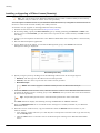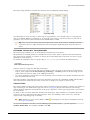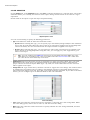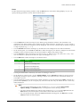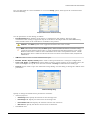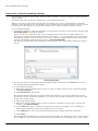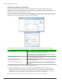
1
InduSoft
Web Studio v7.1
®
User Guide and
Technical Reference
InduSoft
Web Studio v7.1
®
User Guide and
Technical Reference
www.InduSoft.com
[email protected]
062912-UGT-IWS-A-ENA4-PT
InduSoft® is a registered trademark of InduSoft, Inc.
InduSoft Web Studio™, EmbeddedView™, and CEView™ are trademarks of InduSoft, Inc.
Windows, Windows, Windows XP, Windows XP Embedded, Windows Embedded Standard 7,
Windows Embedded Compact, Windows 2003 Server, Windows 2008 Server, Windows Vista, Windows 7,
Windows CE, and Internet Explorer are registered trademarks of Microsoft Corp. in the United States
and other countries.
Other brand or product names are trademarks or registered trademarks of their
respective owners.
Copyright © 2012 InduSoft, Inc. All rights reserved worldwide.
This document shall not be reproduced or copied in any manner without expressed
written authorization from InduSoft.
The information contained within this document is subject to change without notice.
InduSoft, Inc. does not guarantee the accuracy of the information.
PN: 062912-UGT-IWS-A-EN-PT
Contents
Contents
INTRODUCTION.......................................................................................................................................................................... 12
Conventions used in this documentation...............................................................................................................................14
About this software................................................................................................................................................................ 15
Internal structure and data flow............................................................................................................................................. 18
Executing and switching modules......................................................................................................................................... 21
Executing and switching the Background Task..................................................................................................................... 25
INSTALLATION............................................................................................................................................................................27
Comparison of InduSoft Web Studio software components..................................................................................................28
Install the full InduSoft Web Studio software.........................................................................................................................30
Install EmbeddedView or CEView on a target device........................................................................................................... 34
LICENSING.................................................................................................................................................................................. 37
Protection Types....................................................................................................................................................................38
License Settings.................................................................................................................................................................... 39
Execution modes................................................................................................................................................................... 40
Product Versions................................................................................................................................................................... 42
Installing a New Hardkey License......................................................................................................................................... 43
Upgrading the Current Hardkey License............................................................................................................................... 44
Installing a Softkey License...................................................................................................................................................46
Invalid Licenses..................................................................................................................................................................... 48
Installing or Upgrading a CEView License (Locally)..............................................................................................................49
Installing or Upgrading a CEView License (Remotely)..........................................................................................................52
THE DEVELOPMENT ENVIRONMENT...................................................................................................................................... 54
Application button.................................................................................................................................................................. 55
Recent Projects..............................................................................................................................................................55
New................................................................................................................................................................................ 55
Open Project.................................................................................................................................................................. 57
Open.............................................................................................................................................................................. 57
Save............................................................................................................................................................................... 57
Save As.......................................................................................................................................................................... 57
Save All.......................................................................................................................................................................... 58
Save All as HTML.......................................................................................................................................................... 58
Save as HTML............................................................................................................................................................... 58
Save Screen Group as HMTL........................................................................................................................................ 58
Print................................................................................................................................................................................ 58
Print Preview.................................................................................................................................................................. 58
Print Setup..................................................................................................................................................................... 59
Close.............................................................................................................................................................................. 59
Close All......................................................................................................................................................................... 59
Exit................................................................................................................................................................................. 59
Quick Access Toolbar............................................................................................................................................................60
Ribbon................................................................................................................................................................................... 61
Home tab........................................................................................................................................................................61
View tab..........................................................................................................................................................................61
Insert tab........................................................................................................................................................................ 62
Project tab...................................................................................................................................................................... 62
Graphics tab................................................................................................................................................................... 62
Format tab...................................................................................................................................................................... 63
Help tab.......................................................................................................................................................................... 63
Project Explorer..................................................................................................................................................................... 64
Global tab....................................................................................................................................................................... 64
Graphics tab................................................................................................................................................................... 65
Tasks tab........................................................................................................................................................................ 66
Comm tab.......................................................................................................................................................................67
Screen/Worksheet Editor.......................................................................................................................................................68
Database Spy........................................................................................................................................................................ 69
Output (LogWin).................................................................................................................................................................... 70
Title Bar................................................................................................................................................................................. 72
InduSoft Web Studio
Page 1
Contents
Status Bar..............................................................................................................................................................................73
CREATING A NEW PROJECT.................................................................................................................................................... 74
Creating a new project.......................................................................................................................................................... 75
About target platforms and product types...................................................................................................................... 76
Changing the product type of an existing project........................................................................................................... 77
Configuring additional project settings.................................................................................................................................. 79
Information tab............................................................................................................................................................... 79
Options tab..................................................................................................................................................................... 80
Viewer tab...................................................................................................................................................................... 86
Communication tab........................................................................................................................................................ 89
Preferences tab..............................................................................................................................................................90
Configuring your project's default email settings...................................................................................................................93
Configuring your project's default FTP settings.....................................................................................................................94
Starting Modules on the Target System................................................................................................................................ 95
Running a Project Under Windows Services.........................................................................................................................97
TAGS AND THE PROJECT DATABASE.................................................................................................................................. 102
About Tags and the Project Database.................................................................................................................................103
Project Tags Folder...................................................................................................................................................... 104
Classes Folder............................................................................................................................................................. 105
Shared Database Folder.............................................................................................................................................. 107
System Tags Folder..................................................................................................................................................... 107
Designing a Tag...................................................................................................................................................................108
Naming the Tag............................................................................................................................................................ 108
Choosing the Tag Type................................................................................................................................................ 108
Choosing the Tag Data Type........................................................................................................................................110
Choosing the Tag Scope.............................................................................................................................................. 111
Creating Database Tags......................................................................................................................................................112
Adding Tags to the Datasheet...................................................................................................................................... 112
Creating Tags "On-the-Fly".......................................................................................................................................... 112
Editing Tags..................................................................................................................................................................113
Creating Classes................................................................................................................................................................. 115
Setting Tag Properties......................................................................................................................................................... 116
Understanding Tag Properties and Parameters........................................................................................................... 116
Using Tag Properties: Alarms.......................................................................................................................................117
Using Tag Properties: History.......................................................................................................................................119
List of Tag Properties................................................................................................................................................... 119
Using Tags in Your Project.................................................................................................................................................. 124
Deleting a tag from the project database............................................................................................................................ 125
Using the Tags Toolbar........................................................................................................................................................126
Global Replace.............................................................................................................................................................126
Replace........................................................................................................................................................................ 126
Remove unused tags................................................................................................................................................... 127
Reset tags database.................................................................................................................................................... 128
Tag Name text box....................................................................................................................................................... 128
Object Finder................................................................................................................................................................129
Cross Reference.......................................................................................................................................................... 129
Properties..................................................................................................................................................................... 130
Importing an External Database..........................................................................................................................................131
Using the Import Wizard...............................................................................................................................................131
Importing from.............................................................................................................................................................. 133
Tag Integration.....................................................................................................................................................................143
Integrating tags from TwinCAT..................................................................................................................................... 143
Integrating tags from CoDeSys.................................................................................................................................... 146
Integrating tags from RSLogix 5000 Family................................................................................................................. 153
Using the Object Finder to select integrated tags........................................................................................................ 155
How integrated tags may be renamed in your project................................................................................................. 156
SCREENS AND GRAPHICS..................................................................................................................................................... 158
Working with Screens..........................................................................................................................................................159
Screens folder.............................................................................................................................................................. 159
Screen Group Folder....................................................................................................................................................163
Layout.......................................................................................................................................................................... 163
Page 2
InduSoft Web Studio
Contents
Using Screen Objects and Animations................................................................................................................................165
Editing.......................................................................................................................................................................... 165
Shapes......................................................................................................................................................................... 167
Active Objects.............................................................................................................................................................. 172
Libraries....................................................................................................................................................................... 192
Animations................................................................................................................................................................... 210
Formatting Screen Objects..................................................................................................................................................220
Set the tab order of screen objects.............................................................................................................................. 220
Move to Front and Move to Back................................................................................................................................. 221
Move Backward and Move Forward.............................................................................................................................222
Group........................................................................................................................................................................... 222
Align............................................................................................................................................................................. 223
Rotate...........................................................................................................................................................................225
Size.............................................................................................................................................................................. 225
Fill Color....................................................................................................................................................................... 226
Line Color..................................................................................................................................................................... 226
Fonts............................................................................................................................................................................ 226
ALARMS, EVENTS, AND TRENDS.......................................................................................................................................... 228
Alarms................................................................................................................................................................................. 229
Alarm Worksheet Header............................................................................................................................................. 230
Alarm Worksheet Body................................................................................................................................................ 233
Saving your alarm history to an external database...................................................................................................... 234
Format of the alarm history.......................................................................................................................................... 235
Events..................................................................................................................................................................................237
Enabling the event logger............................................................................................................................................ 237
Saving your event log to an external database............................................................................................................ 238
Format of the event log................................................................................................................................................ 239
Alarm/Event Control object..................................................................................................................................................242
Trends................................................................................................................................................................................. 249
Converting Trend History Files from Binary to Text......................................................................................................250
Converting Trend History Files from Text to Binary......................................................................................................251
Creating Batch History................................................................................................................................................. 252
Setting the Trend Database......................................................................................................................................... 254
Trend Control object............................................................................................................................................................ 255
About the trend control runtime interface..................................................................................................................... 255
Object Properties: Trend Control..................................................................................................................................257
Using the Data Source Text File...................................................................................................................................271
Using the Data Source Database.................................................................................................................................273
Grid object........................................................................................................................................................................... 278
Columns dialog............................................................................................................................................................ 279
Data dialog................................................................................................................................................................... 281
Advanced dialog...........................................................................................................................................................282
BACKGROUND TASKS............................................................................................................................................................ 285
Alarms................................................................................................................................................................................. 286
Trends................................................................................................................................................................................. 288
Recipes............................................................................................................................................................................... 290
Reports................................................................................................................................................................................ 292
ODBC.................................................................................................................................................................................. 294
Math.....................................................................................................................................................................................296
Script................................................................................................................................................................................... 297
Startup Script worksheet.............................................................................................................................................. 298
Scheduler............................................................................................................................................................................ 299
Database/ERP worksheet................................................................................................................................................... 301
COMMUNICATION WITH OTHER DEVICES............................................................................................................................ 305
Drivers................................................................................................................................................................................. 306
Main Driver Sheet........................................................................................................................................................ 311
Standard Driver Sheets................................................................................................................................................313
OPC DA 2.05.......................................................................................................................................................................316
OPC UA...............................................................................................................................................................................321
OPC .Net............................................................................................................................................................................. 326
OPC XML/DA...................................................................................................................................................................... 331
InduSoft Web Studio
Page 3
Contents
TCP/IP................................................................................................................................................................................. 335
DDE..................................................................................................................................................................................... 337
COLLABORATION AND SOURCE CONTROL........................................................................................................................ 339
Connect to your collaboration server...................................................................................................................................340
Add a project to source control............................................................................................................................................342
Check out project files for editing........................................................................................................................................ 343
View, undo, or check in pending changes........................................................................................................................... 344
Branch a project in source control.......................................................................................................................................346
Open a project from source control..................................................................................................................................... 347
Get the latest version of a project........................................................................................................................................348
Get a specific version of a project....................................................................................................................................... 349
Apply a label to a project..............................................................................................................................................349
PROJECT SECURITY............................................................................................................................................................... 350
About security modes..........................................................................................................................................................351
About security access levels............................................................................................................................................... 352
Using the security system configuration wizard.................................................................................................................. 354
Configuring server settings for security modes................................................................................................................... 357
Extending the LDAP schema to allow saving of security rights................................................................................... 360
Creating and configuring groups......................................................................................................................................... 368
Creating and configuring users........................................................................................................................................... 372
Managing an existing security system.................................................................................................................................373
Backing up the security system configuration..................................................................................................................... 375
Logging on/off......................................................................................................................................................................377
Blocking or unblocking a user............................................................................................................................................. 378
Password Protection of Project Files...................................................................................................................................379
PROJECT LOCALIZATION....................................................................................................................................................... 380
Add a language to the Translation Table............................................................................................................................ 381
Configure fonts for a target language..................................................................................................................................383
Examples of font configuration.....................................................................................................................................384
Set the project's language at startup................................................................................................................................... 386
Set the project's language during run time.......................................................................................................................... 387
Disable translation of selected screen objects.................................................................................................................... 388
TESTING AND DEBUGGING.................................................................................................................................................... 389
Debugging from the Output Window................................................................................................................................... 390
Debugging from the Database Spy..................................................................................................................................... 392
Using the LogWin Module................................................................................................................................................... 393
Using Remote Tools............................................................................................................................................................ 394
Using Remote Database Spy.......................................................................................................................................394
Using Remote LogWin................................................................................................................................................. 394
REMOTE MANAGEMENT......................................................................................................................................................... 396
Install EmbeddedView or CEView on a target device......................................................................................................... 397
Enable security in Remote Agent and add users................................................................................................................ 400
Customize Remote Agent's encryption key................................................................................................................. 401
License the runtime software on the target device..............................................................................................................403
Download your project to the target device......................................................................................................................... 404
Run or stop your project on the target device..................................................................................................................... 406
Configure Remote Agent to autorun a project.....................................................................................................................407
THIN CLIENTS AND MOBILE ACCESS................................................................................................................................... 408
Page 4
InduSoft Web Studio
Contents
Web..................................................................................................................................................................................... 410
Building a Simple Application.......................................................................................................................................410
The Underlying Technology..........................................................................................................................................417
ISSymbol Control Layer............................................................................................................................................... 418
Examples of Client/Server Architecture....................................................................................................................... 420
Configuring the Data Server.........................................................................................................................................423
Configuring a web server to host your project pages...................................................................................................426
Installing the web tunneling gateway........................................................................................................................... 427
Configuring the Thin Client...........................................................................................................................................429
Implementing Security..................................................................................................................................................433
Port Usage................................................................................................................................................................... 436
Exercise: Viewing Your Project on the Web................................................................................................................. 436
Mobile Access..................................................................................................................................................................... 438
Turn on Microsoft IIS.................................................................................................................................................... 439
Enable SSL encryption in Microsoft IIS........................................................................................................................440
Install the MA runtime software....................................................................................................................................442
Insert a new area in the MA site hierarchy...................................................................................................................442
Configure the area settings.......................................................................................................................................... 443
Configure the global settings........................................................................................................................................446
Log on to the MA website during run time....................................................................................................................447
Navigate the Mobile Access website............................................................................................................................448
Mobile Access Tabular........................................................................................................................................................ 454
DATABASE INTERFACE...........................................................................................................................................................457
SQL Relational Databases.................................................................................................................................................. 458
Linking the Database Through a Remote DB Provider....................................................................................................... 460
Studio Database Gateway...................................................................................................................................................461
Database Configuration.......................................................................................................................................................466
Configuring a Default Database for All Task History........................................................................................................... 470
Database Troubleshooting.................................................................................................................................................. 471
Appendices..........................................................................................................................................................................474
Using ODBC Databases.............................................................................................................................................. 474
Using Microsoft SQL Server.........................................................................................................................................475
Using ORACLE Databases.......................................................................................................................................... 476
Using Microsoft Access Databases..............................................................................................................................478
Using SQL Server CE.................................................................................................................................................. 479
Using Sybase............................................................................................................................................................... 481
Using Microsoft Excel...................................................................................................................................................482
Using MySQL............................................................................................................................................................... 484
TROUBLESHOOTING............................................................................................................................................................... 486
General Troubleshooting..................................................................................................................................................... 487
Frequently Asked Questions............................................................................................................................................... 489
Getting help......................................................................................................................................................................... 496
Technical Reference.....................................................................................................................................................496
Communication Drivers................................................................................................................................................496
License Agreement...................................................................................................................................................... 496
Home Page.................................................................................................................................................................. 496
Release Notes..............................................................................................................................................................496
System Information...................................................................................................................................................... 497
Support Information......................................................................................................................................................497
About............................................................................................................................................................................ 498
APPENDIX: BUILT-IN SCRIPTING LANGUAGE......................................................................................................................499
Logic and arithmetic operators............................................................................................................................................ 500
How to read function descriptions....................................................................................................................................... 502
Log Message functions....................................................................................................................................................... 504
Trace............................................................................................................................................................................ 504
InduSoft Web Studio
Page 5
Contents
Arithmetic functions............................................................................................................................................................. 505
Abs............................................................................................................................................................................... 505
Div................................................................................................................................................................................ 505
Format.......................................................................................................................................................................... 506
GetBit........................................................................................................................................................................... 508
Mod.............................................................................................................................................................................. 509
Pow.............................................................................................................................................................................. 510
ResetBit........................................................................................................................................................................510
Round...........................................................................................................................................................................511
SetBit............................................................................................................................................................................511
Sqrt...............................................................................................................................................................................512
Swap16........................................................................................................................................................................ 513
Swap32........................................................................................................................................................................ 513
Trunc............................................................................................................................................................................ 513
Statistical functions..............................................................................................................................................................515
Avg............................................................................................................................................................................... 515
Max.............................................................................................................................................................................. 515
Min............................................................................................................................................................................... 516
Rand.............................................................................................................................................................................517
Logarithmic functions.......................................................................................................................................................... 518
Exp............................................................................................................................................................................... 518
Log............................................................................................................................................................................... 518
Log10........................................................................................................................................................................... 518
Logical functions..................................................................................................................................................................520
False............................................................................................................................................................................ 520
If................................................................................................................................................................................... 520
Toggle...........................................................................................................................................................................521
True.............................................................................................................................................................................. 521
String functions....................................................................................................................................................................523
Asc2Str.........................................................................................................................................................................523
CharToValue.................................................................................................................................................................523
CharToValueW............................................................................................................................................................. 524
ClassMembersToStrVector...........................................................................................................................................525
NCopy.......................................................................................................................................................................... 525
Num..............................................................................................................................................................................526
Str.................................................................................................................................................................................527
Str2Asc.........................................................................................................................................................................527
StrCompare.................................................................................................................................................................. 527
StrCompareNoCase.....................................................................................................................................................528
StrFromInt.................................................................................................................................................................... 529
StrFromReal................................................................................................................................................................. 529
StrFromTime................................................................................................................................................................ 530
StrGetElement..............................................................................................................................................................531
StrLeft...........................................................................................................................................................................531
StrLen...........................................................................................................................................................................532
StrLower....................................................................................................................................................................... 532
StrRChr........................................................................................................................................................................ 533
StrRight........................................................................................................................................................................ 533
StrSetElement.............................................................................................................................................................. 534
StrStr............................................................................................................................................................................ 534
StrStrPos...................................................................................................................................................................... 535
StrTrim..........................................................................................................................................................................535
StrTrimAll......................................................................................................................................................................536
StrUpper....................................................................................................................................................................... 536
ValueToChar.................................................................................................................................................................537
ValueWToChar............................................................................................................................................................. 537
Page 6
InduSoft Web Studio
Contents
Date & Time functions......................................................................................................................................................... 539
ClockGetDate...............................................................................................................................................................539
ClockGetDayOfWeek................................................................................................................................................... 539
ClockGetTime...............................................................................................................................................................540
DateTime2Clock...........................................................................................................................................................540
GetClock...................................................................................................................................................................... 541
Hour2Clock.................................................................................................................................................................. 541
SetSystemDate............................................................................................................................................................ 542
SetSystemTime............................................................................................................................................................ 542
Trigonometric functions....................................................................................................................................................... 544
ACos............................................................................................................................................................................ 544
ASin..............................................................................................................................................................................544
ATan............................................................................................................................................................................. 545
Cos............................................................................................................................................................................... 545
Cot................................................................................................................................................................................545
Pi.................................................................................................................................................................................. 546
Sin................................................................................................................................................................................ 546
Tan............................................................................................................................................................................... 547
Screen functions..................................................................................................................................................................548
Close............................................................................................................................................................................ 548
Open............................................................................................................................................................................ 548
OpenPrevious.............................................................................................................................................................. 550
ShowInplaceInput.........................................................................................................................................................551
ShowMessageBox....................................................................................................................................................... 552
Security functions................................................................................................................................................................ 554
BlockUser..................................................................................................................................................................... 554
CheckESign................................................................................................................................................................. 554
CreateUser................................................................................................................................................................... 555
ExportSecuritySystem..................................................................................................................................................556
GetSecuritySystemStatus............................................................................................................................................ 557
GetUserFullName........................................................................................................................................................ 558
GetUserNames............................................................................................................................................................ 558
GetUserPwdAging........................................................................................................................................................559
GetUserState............................................................................................................................................................... 560
ImportSecuritySystem.................................................................................................................................................. 560
RemoveUser................................................................................................................................................................ 561
SetPassword................................................................................................................................................................ 562
UnblockUser.................................................................................................................................................................563
InduSoft Web Studio
Page 7
Contents
Module Activity functions.....................................................................................................................................................565
AppActivate.................................................................................................................................................................. 565
AppIsRunning...............................................................................................................................................................566
AppPostMessage......................................................................................................................................................... 567
AppSendKeys.............................................................................................................................................................. 568
CleanReadQueue........................................................................................................................................................ 568
CloseSplashWindow.................................................................................................................................................... 569
DisableMath................................................................................................................................................................. 569
EnableMath.................................................................................................................................................................. 569
EndTask....................................................................................................................................................................... 570
ExitWindows.................................................................................................................................................................571
IsScreenOpen.............................................................................................................................................................. 571
IsTaskRunning..............................................................................................................................................................572
IsViewerInFocus...........................................................................................................................................................572
KeyPad.........................................................................................................................................................................572
LogOff...........................................................................................................................................................................574
LogOn.......................................................................................................................................................................... 574
Math............................................................................................................................................................................. 575
PostKey........................................................................................................................................................................ 575
Recipe.......................................................................................................................................................................... 576
Report.......................................................................................................................................................................... 576
RunGlobalProcedureAsync..........................................................................................................................................577
RunGlobalProcedureAsyncGetStatus..........................................................................................................................579
RunGlobalProcedureOnFalse...................................................................................................................................... 580
RunGlobalProcedureOnServer.................................................................................................................................... 581
RunGlobalProcedureOnTrigger....................................................................................................................................582
RunGlobalProcedureOnTrue........................................................................................................................................582
RunVBScript.................................................................................................................................................................583
SecureViewerReload................................................................................................................................................... 584
SendKeyObject............................................................................................................................................................ 585
SetAppPath.................................................................................................................................................................. 586
SetViewerInFocus........................................................................................................................................................ 587
SetViewerPos...............................................................................................................................................................587
ShutDown.....................................................................................................................................................................588
StartTask...................................................................................................................................................................... 588
ViewerPostMessage.................................................................................................................................................... 589
WinExec....................................................................................................................................................................... 590
WinExecIsRunning.......................................................................................................................................................591
File functions....................................................................................................................................................................... 593
DeleteOlderFiles.......................................................................................................................................................... 593
DirCreate...................................................................................................................................................................... 593
DirDelete...................................................................................................................................................................... 594
DirLength......................................................................................................................................................................594
DirRename................................................................................................................................................................... 595
FileCopy....................................................................................................................................................................... 596
FileDelete..................................................................................................................................................................... 596
FileLength.................................................................................................................................................................... 597
FileRename..................................................................................................................................................................597
FileWrite....................................................................................................................................................................... 598
FindFile........................................................................................................................................................................ 598
FindPath....................................................................................................................................................................... 600
GetFileAttributes.......................................................................................................................................................... 600
GetFileTime..................................................................................................................................................................601
GetHstInfo.................................................................................................................................................................... 601
GetLine.........................................................................................................................................................................602
HST2TXT..................................................................................................................................................................... 604
HST2TXTIsRunning..................................................................................................................................................... 605
LookupContains........................................................................................................................................................... 605
LookupGet....................................................................................................................................................................606
LookupLoad................................................................................................................................................................. 606
PDFCreate................................................................................................................................................................... 607
Print.............................................................................................................................................................................. 608
RDFileN........................................................................................................................................................................609
WebGetFile.................................................................................................................................................................. 609
Page 8
InduSoft Web Studio
Contents
Graphic functions................................................................................................................................................................ 611
AutoFormat.................................................................................................................................................................. 611
GetScrInfo.................................................................................................................................................................... 611
PrintSetup.................................................................................................................................................................... 612
PrintWindow................................................................................................................................................................. 613
ResetDecimalPointsTable............................................................................................................................................ 614
RGBColor..................................................................................................................................................................... 614
RGBComponent...........................................................................................................................................................615
SaveScreenShot.......................................................................................................................................................... 615
SetDecimalPoints.........................................................................................................................................................617
SetDisplayUnit..............................................................................................................................................................618
SetTagDisplayUnit........................................................................................................................................................618
Translation functions........................................................................................................................................................... 620
Ext................................................................................................................................................................................ 620
SetLanguage................................................................................................................................................................620
SetTranslationFile........................................................................................................................................................ 621
Multimedia functions............................................................................................................................................................622
Play.............................................................................................................................................................................. 622
System Info functions.......................................................................................................................................................... 623
DbVersion.....................................................................................................................................................................623
GetAppHorizontalResolution........................................................................................................................................623
GetAppPath..................................................................................................................................................................623
GetAppVerticalResolution............................................................................................................................................ 624
GetComputerIP............................................................................................................................................................ 624
GetComputerName...................................................................................................................................................... 625
GetCursorX.................................................................................................................................................................. 625
GetCursorY.................................................................................................................................................................. 625
GetDisplayHorizontalResolution.................................................................................................................................. 626
GetDisplayVerticalResolution.......................................................................................................................................626
GetFreeMemoryCE...................................................................................................................................................... 626
GetHardKeyModel........................................................................................................................................................627
GetHardKeySN............................................................................................................................................................ 627
GetIPAll........................................................................................................................................................................ 628
GetMemoryCE............................................................................................................................................................. 628
GetNetMACID.............................................................................................................................................................. 629
GetOS.......................................................................................................................................................................... 630
GetPerformanceMetric................................................................................................................................................. 630
GetPrivateProfileString.................................................................................................................................................633
GetProductPath............................................................................................................................................................634
GetRegValue................................................................................................................................................................ 634
GetRegValueType........................................................................................................................................................ 635
GetServerHostName....................................................................................................................................................636
GetTickCount............................................................................................................................................................... 636
InfoAppAlrDir................................................................................................................................................................ 636
InfoAppHSTDir............................................................................................................................................................. 637
InfoDiskFree................................................................................................................................................................. 637
InfoResources.............................................................................................................................................................. 637
IsActiveXReg................................................................................................................................................................638
IsAppChangedOnServer.............................................................................................................................................. 638
NoInputTime.................................................................................................................................................................639
ProductVersion.............................................................................................................................................................640
RegSaveCE................................................................................................................................................................. 640
ReloadAppFromServer................................................................................................................................................ 641
SaveAlarmFile..............................................................................................................................................................641
SetAppAlarmPath.........................................................................................................................................................642
SetAppHSTPath...........................................................................................................................................................642
SetDateFormat.............................................................................................................................................................643
SetKeyboardLanguage................................................................................................................................................ 643
SetRegValue................................................................................................................................................................ 644
SetWebConfig.............................................................................................................................................................. 645
SNMPGet..................................................................................................................................................................... 647
SNMPSet..................................................................................................................................................................... 648
WritePrivateProfileString.............................................................................................................................................. 649
InduSoft Web Studio
Page 9
Contents
Tags Database functions..................................................................................................................................................... 650
ExecuteAlarmAck.........................................................................................................................................................650
ForceTagChange..........................................................................................................................................................651
GetTagValue.................................................................................................................................................................651
SetTagValue................................................................................................................................................................. 652
Loop functions..................................................................................................................................................................... 653
For … Next................................................................................................................................................................... 653
ODBC functions...................................................................................................................................................................654
ODBCBeginTrans.........................................................................................................................................................654
ODBCBindCol.............................................................................................................................................................. 654
ODBCCanAppend........................................................................................................................................................655
ODBCCanTransact...................................................................................................................................................... 656
ODBCCanUpdate.........................................................................................................................................................656
ODBCClose..................................................................................................................................................................656
ODBCCommitTrans..................................................................................................................................................... 657
ODBCDelete................................................................................................................................................................ 657
ODBCExecuteSQL.......................................................................................................................................................658
ODBCInsert.................................................................................................................................................................. 658
ODBCIsBOF.................................................................................................................................................................659
ODBCIsDeleted............................................................................................................................................................659
ODBCIsEOF.................................................................................................................................................................660
ODBCIsFieldNULL....................................................................................................................................................... 660
ODBCIsFieldNullable................................................................................................................................................... 661
ODBCMove.................................................................................................................................................................. 661
ODBCMoveFirst........................................................................................................................................................... 662
ODBCMoveLast........................................................................................................................................................... 662
ODBCMoveNext...........................................................................................................................................................663
ODBCMovePrev...........................................................................................................................................................663
ODBCOpen.................................................................................................................................................................. 664
ODBCQuery................................................................................................................................................................. 665
ODBCRollBack.............................................................................................................................................................665
ODBCSetFieldNULL.................................................................................................................................................... 666
ODBCSetFilter............................................................................................................................................................. 666
ODBCSetSort............................................................................................................................................................... 667
ODBCUnbindCol.......................................................................................................................................................... 667
ODBCUpdate............................................................................................................................................................... 668
Email functions.................................................................................................................................................................... 669
CnfEmail.......................................................................................................................................................................669
GetStatusSendEmailExt...............................................................................................................................................671
SendEmail.................................................................................................................................................................... 671
SendEmailExt...............................................................................................................................................................672
Dial-up functions..................................................................................................................................................................674
DialError....................................................................................................................................................................... 674
DialGetClientIP.............................................................................................................................................................678
DialGetServerIP........................................................................................................................................................... 680
DialStatus..................................................................................................................................................................... 681
DialUp.......................................................................................................................................................................... 682
DialUpToCE..................................................................................................................................................................684
FindAllDevices............................................................................................................................................................. 685
FindModem.................................................................................................................................................................. 685
HangUp........................................................................................................................................................................ 686
PhoneDialUp................................................................................................................................................................ 687
PhoneDisableListen..................................................................................................................................................... 687
PhoneEnableListen...................................................................................................................................................... 688
PhoneHangUp..............................................................................................................................................................688
PhoneStatus.................................................................................................................................................................689
ActiveX and .NET Control functions.................................................................................................................................... 691
XGet............................................................................................................................................................................. 691
XRun............................................................................................................................................................................ 691
XSet............................................................................................................................................................................. 692
Event Logger functions........................................................................................................................................................693
SendEvent....................................................................................................................................................................693
Page 10
InduSoft Web Studio
Contents
FTP functions...................................................................................................................................................................... 694
CnfFTP......................................................................................................................................................................... 694
FTPGet.........................................................................................................................................................................695
FTPPut......................................................................................................................................................................... 696
FTPStatus.................................................................................................................................................................... 697
Database/ERP functions..................................................................................................................................................... 699
DBCursorClose............................................................................................................................................................ 699
DBCursorColumnCount............................................................................................................................................... 699
DBCursorColumnInfo................................................................................................................................................... 700
DBCursorCurrentRow.................................................................................................................................................. 701
DBCursorGetValue.......................................................................................................................................................702
DBCursorMoveTo.........................................................................................................................................................702
DBCursorNext.............................................................................................................................................................. 703
DBCursorOpen.............................................................................................................................................................704
DBCursorOpenSQL..................................................................................................................................................... 705
DBCursorPrevious....................................................................................................................................................... 706
DBCursorRowCount.....................................................................................................................................................707
DBDelete...................................................................................................................................................................... 708
DBExecute................................................................................................................................................................... 709
DBInsert....................................................................................................................................................................... 710
DBSelect...................................................................................................................................................................... 711
DBUpdate.....................................................................................................................................................................712
SyncAlarm.................................................................................................................................................................... 713
SyncAlarmStatus..........................................................................................................................................................714
SyncEvent.................................................................................................................................................................... 715
SyncEventStatus..........................................................................................................................................................715
SyncTrend.................................................................................................................................................................... 716
SyncTrendStatus..........................................................................................................................................................717
APPENDIX: VBSCRIPT............................................................................................................................................................. 718
VBScript Interfaces in the Software.....................................................................................................................................719
Global Procedures....................................................................................................................................................... 720
Graphic Module............................................................................................................................................................722
Background Task..........................................................................................................................................................728
Language Reference...........................................................................................................................................................730
Operators..................................................................................................................................................................... 730
Constants..................................................................................................................................................................... 731
Objects and Collections............................................................................................................................................... 733
Properties..................................................................................................................................................................... 734
Statements................................................................................................................................................................... 734
Methods....................................................................................................................................................................... 735
Functions......................................................................................................................................................................736
Keywords..................................................................................................................................................................... 736
Errors........................................................................................................................................................................... 737
Tips & Tricks........................................................................................................................................................................ 740
VBScript Editor IntelliSense......................................................................................................................................... 740
VBScript Compared to VBA......................................................................................................................................... 741
Screen Events..............................................................................................................................................................743
MsgBox and InputBox Functions................................................................................................................................. 743
VBScript Procedures....................................................................................................................................................743
Creating Constants...................................................................................................................................................... 744
Declaring Variables...................................................................................................................................................... 745
Scope and Lifetime of Variables...................................................................................................................................745
Boolean Tags and Boolean Variables.......................................................................................................................... 745
Writing Real Values to Integer Tags............................................................................................................................. 746
Precedence of VBScript Operators.............................................................................................................................. 747
Logical Operator NOT.................................................................................................................................................. 747
Using Conditional Statements......................................................................................................................................748
Looping Through Code................................................................................................................................................ 749
Support for ActiveX Controls........................................................................................................................................752
Windows Embedded Support.......................................................................................................................................752
InduSoft Web Studio
Page 11
Introduction
Introduction
This User Guide and Technical Reference was designed to help you get the best results from your InduSoft
Web Studio™ software. This document provides technical information and step-by-step instructions for all
the tasks you need to create Web-enabled HMI/SCADA programs.
Who should read this
This User Guide and Technical Reference is a comprehensive document designed to provide useful
information for both novice and advanced users of IWS.
•
New Users: This publication uses a step-by-step, hands-on approach to the project development
process. Be sure to read the introductory chapters describing the product's features and development
environment.
•
Experienced Users: This publication offers advanced instructions, tips, and troubleshooting
information to help you get the most out of your projects.
Note: We assume you are familiar with working in a Windows environment, and we do not
attempt to explain Windows navigation, file management, and so forth. If you are unfamiliar
with any of these procedures, we recommend using the Windows Help feature (Start > Help) or
consulting your Microsoft Windows documentation.
Contents
The information in this document is organized into the following chapters:
•
Page 12
This chapter: Describes the purpose, content, and organization of the User Guide and Technical
Reference. In addition, this chapter contains the following information:
•
Explains the formatting, mouse, and Windows conventions used
•
Lists other publications providing information about IWS
•
Explains how to contact a technical support representative
•
About This Software: Provides a high-level overview of the product's uses, features, and functions.
•
Installing and Uninstalling: Provides step-by-step instructions for installing, licensing, starting, and
uninstalling InduSoft Web Studio and CEView.
•
Navigating the Development Environment: Describes the IWS interface (or development
environment), and explains some basic skills and techniques you must understand before creating a
new project.
•
How the Software Works: Describes the internal structure of IWS, including how data flows through
the runtime modules and how these modules are executed.
•
Creating and Configuring a New Project: Provides step-by-step instructions for creating and
configuring a new project.
•
Working with Tags: Explains basic concepts about the product database, tag types (arrays, classes,
and pointers), tag values and parameters. Following the concepts discussion, this chapter provides
instructions for creating and editing tags for your projects.
•
Creating Screens and Graphics: Explains how to use the different IWS development tools to create
your project screens and graphics.
•
Configuring Background Tasks: Explains how to create and configure the different IWS task
worksheets for your projects.
•
Event Settings: Describes the logging and event-retrieval features.
•
Communicating with Other Devices: Describes how to configure your project to read from and write
to a device's registers. The information includes instructions for configuring drivers and OPC, TCP/IP,
and DDE communication.
•
Configuring a Security System: Explains how to set-up and manage a security system for your
projects.
•
Testing and Debugging Your Project: Discusses how to test and debug projects using tools such as
the Database Spy and Output windows. This chapter includes a list of possible error messages and
methods for correcting those errors.
InduSoft Web Studio
Introduction
•
Configuring a Web Solution: Explains how configure and run your projects on the Web.
•
Downloading to a Remote Device: Explains how to download, monitor, and debug projects from a
remote runtime workstation.
•
Using the Translation Tool: Explains how to use the Translation Tool to translate the text in your
projects from one language to another.
•
Database Interface: Explains how to connect IWS to compatible databases.
•
Scripting Languages: Describes IWS's built-in scripting language, as well as the support for VBScript
in IWS.
•
Troubleshooting and FAQs: Provides instructions for verifying projects, describes some common
development errors, and explains what to do if you need to contact a support representative.
Related documentation
You may want to review the following manuals in addition to this Technical Reference:
•
Getting Started Manual: Provides basic information about InduSoft Web Studio, including a systematic
tutorial that allows you to develop a single project and become familiar with the product in a short
time.
•
Tutorial Manual: Describes how to build an project, step-by-step, with the main product features. You
can use this document as a self-training manual.
•
Drivers User Guides: Explain how to configure individual direct communication drivers, according to
their unique protocol characteristics. One customized user guide is included with each driver.
Note: All manuals are located in the Documentation folder on the IWS installation CD. IWS
installs the Drivers User Guides in the\Drv folder in the program directory. You also can access
technical information from the Help menu.
InduSoft Web Studio
Page 13
Introduction
Conventions used in this documentation
This documentation uses standardized formatting and terminology to make it easier for all users to
understand.
Text conventions
This documentation uses special text formatting to help you quickly identify certain items:
•
Titles, labels, new terms, and messages are indicated using italic text (for example, Object Properties).
•
File names, screen text, and text you must enter are indicated using monospace text (for example, D:
\Setup.exe ).
•
Buttons, menu options, and keyboard keys are indicated using a bold typeface (for example, File menu).
In addition, this documentation segregates some text into Tip, Note, and Caution boxes:
•
Tips provide useful information to save development time or to improve the project performance.
•
Notes provide extra information that may make it easier to understand the nearby text, usually the
text just before the note.
•
Cautions provide information necessary to prevent errors that can cause problems when running the
project, and may result in damage.
Mouse and selection conventions
Because most PCs used for project development run a version of Microsoft Windows with a mouse, this
documentation assumes you are using a mouse. Generally, a PC mouse is configured for right-handed
use, so that the left mouse button is the primary button and the right mouse button is the secondary
button.
This documentation uses the following mouse and selection conventions:
•
Click and Select both mean to click once on an item with the left mouse button. In general, you click
buttons and you select from menus and lists.
•
Double-click means to quickly click twice on an item with the left mouse button.
•
Right-click means to click once on an item with the right mouse button.
•
Select also means you should use your pointing device to highlight or specify an item on the computer
screen. Selecting an item with a touchscreen is usually the same as selecting with a mouse, except
that you use your finger to touch (select) a screen object or section. To select items with your keyboard,
you typically use the Tab key to move around options, the Enter key to open menus, and the Alt key
with a letter key to select an object that has an underlined letter.
•
Drag means to press down the appropriate mouse button and move the mouse before releasing the
button. Usually an outline of the item will move with the mouse cursor.
Windows conventions
This documentation uses the following Windows conventions:
Page 14
•
Dialogs are windows that allow you to configure settings and enter information.
•
Text boxes are areas in dialogs where you can type text.
•
Radio buttons are white circles in which a black dot appears or disappears when you click on the
button. Typically, the dot indicates the option is selected or enabled. No dot indicates the option is
cleared or disabled.
•
Check boxes are white squares in which a check (
) appears or disappears when you click on it
with the cursor. Typically, a check indicates the option is selected or enabled. No check indicates
the option is cleared or disabled.
•
Buttons are icons in boxes appear "pressed" when you click on them.
•
Lists are panes (white boxes) in windows or dialogs containing two or more selectable options.
•
Combo boxes have arrows that, when clicked, show part or all of an otherwise concealed list.
•
Dockable windows are windows that you can drag to an edge of the interface and merge with that
edge.
InduSoft Web Studio
Introduction
About this software
InduSoft Web Studio is powerful software for developing HMI, SCADA, and OEE/Dashboard projects that
can be deployed anywhere.
Each IWS project consists of:
•
A project tags database to manage all runtime data, including both internal variables and scanned I/O;
•
Configurable drivers to communicate in real-time with programmable logic controllers (PLCs), remote
I/O devices, and other data-acquisition equipment;
•
Animated HMI screens and OEE dashboards; and
•
Optional modules such as alarms, events, trends, recipes, reports, scriptable logic, schedulers, a
security system, and a complete database interface.
After you develop your project, you can either run it locally on your development workstation or download
it to a remote workstation and run it there using InduSoft Web Studio or EmbeddedView/CEView
runtime software. The workstation processes I/O data from connected devices according to your project
parameters and then reacts to, displays, and/or saves the data.
Product features
Alarms
In addition to all the alarm functions you'd expect, IWS v7.1 also sends alarms using multimedia formats like PDF. Use remote notification to have alarms sent right to your inbox, a
printer, or a smartphone! Alarms are real-time and historical, log data in binary format or to
any database.
Animation
IWS gives you great command over graphics. Paste images, and even rotate them
dynamically. Fill bar graphs with color, or adjust the scale of objects with easy-to-use
configuration. Other animations include "command" (for touch, keyboard and mouse
interaction), hyperlink, text data link, color, resize (independent height and width), position,
and rotation (with custom rotation point).
Database
Connect to any SQL database (MS SQL, MySQL, Sybase, Oracle), or MS Access or Excel, and
ERP/MES systems (including SAP), even from Windows Embedded CE. Flexible enough to
have a built in interface without the need for knowing SQL (for trends, alarms/events, grid
and other objects), or use any SQL statement you need anywhere you need it.
Drivers
IWS v7.1 contains over 240 built-in drivers for most PLCs, temperature controllers, motion
controllers, and bar code/2D/RFID readers. InduSoft driver toolkits allow you the flexibility
to build your own drivers. Use these built in drivers without the need for OPC servers (but
are an optional connection method).
Email
Send email using SMTP to desktop, email enabled phone, or any enabled device. Get realtime information on alarms, process values, and other events. InduSoft Web Studio v7.1
supports SSL encryption allowing the use of third-party providers such as Gmail.
Events
IWS v7.1 offers traceability for operator initiated actions or internal system activity. Log
events such as security system changes (user logon or off), screen open/close, recipe/report
operations, custom messages and system warnings. Also any tag value changes including
custom messages.
FDA Traceability
Take advantage of built-in functionality to create 21 CFR part 11 compliant projects with
traceability and e-signatures. These features are often used for pharmaceutical and food
applications, but also for any application where traceability is a must.
FTP
InduSoft Web Studio
Page 15
Introduction
Automatically upload or download files during runtime to/from remote storage locations
using FTP protocol and flexible scripting functions. Configure FTP via scripting or the
included configuration interface.
Graphics and Design Tools
Create powerful screens to meet any application need using the improved tools in our
graphic interface. Combine built-in objects to create any functionality required. Store
graphics in the library for future use, or easily make project across a product line share a
consistent "look and feel".
Historical Performance
We have optimized the trend history module, and designed it to load millions of values from
SQL Relational Databases with high performance, with built-in data decimation in the Trend
Control. Easy to use tools provide quick access to Statistical Process Control (SPC) values
without any need for programming.
Intellectual Property Protection
Screens, documents, scripts and even math worksheets can be individually password
protected. This prevents unauthorized viewing or editing of your corporate custom
functionality. Protect the entire project with just a few mouse clicks.
Multi-Language
Develop your application in one of many development languages, including English,
Portuguese, German, and French.
.NET and ActiveX
Use third-party controls to enhance your project. IWS is a container for ActiveX and .NET
controls. Add functionality such as browsers, media players, charting, and other tools that
support the ActiveX or .NET interface standards.
OPC
Drivers for all major brands of PLCs are built in, but any OPC server may optionally be used.
IWS supports OPC DA (Server/Client), OPC HDA(Server), UA (Client) and OPC .NET 3.0
(Client). InduSoft Web Studio v7.1 also supports OPC XML as an additional add-on.
PDF Export
Send Alarms, Reports, or any file (including .doc or .txt) to a production supervisor, quality
manager, or maintenance staff using the included PDF writer.
Recipes
Save time and maintain consistency by automating part parameters or productions
quantities with any triggering event.
Redundancy
For critical applications where data is vital, IWS v7.1 supports web server, database and
overall system redundancy.
Reports
Create clear, concise reports in text format, graphical RTF, XML, PDF, HTML, and CSV or
integrate with Microsoft Office. Get the data you need, in the format you need it, to make
informed decisions, fast.
Scalable
Develop once and deploy everywhere. Take an application created for Windows CE and
deploy it on any supported Microsoft operating system, including Embedded, Windows 7
(and soon Windows 8), and Server editions.
Scheduler
Schedule custom tag changes on date/time, frequency, or any trigger. Use this for
simulation, to trigger reports or other functionality at a particular time of day, or even to
trigger driver worksheets to read/write at a scan rate you choose.
Scripting
Page 16
InduSoft Web Studio
Introduction
Two powerful scripting languages are supported. Use built-in InduSoft functions or use
standard VBScript to take advantage of widely available resources. Both can be used
simultaneously to give you the functionality you need.
Security
IWS includes support for group and user accounts, e-signatures, and traceability, as well as
support for the ADAM Server, in addition to standard LDAP Servers. Integrate your project to
the Active Directory (Users and Groups).
SSL Support for Emails
Native support for Secure Socket Layer (SSL), makes it easy and secure to send emails from
InduSoft Web Studio using third-party tools such as Gmail!
Standards
Take advantage of common industry standards to develop applications that are compatible
with any format. TCP/IP, .Net, ActiveX, OPC (client and server), ADO/ODBC, COM/DCOM,
OLE, DDE, XML, SOAP, and HTML are supported.
SNMP
Easily configure managed networked devices on IP networks (such as switches and routers)
using incorporated SNMP configuration commands and an easy-to-use configuration
interface.
Symbols
Included library features push buttons, pilot lights, tanks, sliders, meters, motors, pipes,
valves and other common objects. Use the included symbols in your project, modify existing
symbols to suit your needs, or create your own from scratch. Plus support for third-party
symbol libraries and graphic tools.
Tag Database
IWS features an object oriented database with boolean, integer, real, strings, arrays, classes
(structures), indirect tags and included system tags.
Thin Clients
Remotely view screens as web pages using Internet Explorer web browser, or InduSoft
Secure Viewer. Use SMA (Studio Mobile Access) to monitor or access process values and
alarms with remote devices such as tablets and mobile phones. Enhanced SMA offers data
in easy-to-read widgets that can be viewed on any WebKit (HTML5) based web browser found
on iPads, and Android phones and tablets.
Trends
Real-time and Historical trends are supported. Log data in binary format or to any database
locally and remotely. Color or fill trends with graphic elements to enhance clarity of data.
Date/Time based or numeric (X/Y plot) trends give you the flexibility to display information
that best suits your application.
Troubleshooting
Quickly debug and verify a project using local and remote tools for troubleshooting,
including status fields, DatabaseSpy and LogWin. Capture screen open and close times,
see communications in real-time, and messages related to OPC, recipes/reports, security,
database errors and even custom messages. Quickly get your project finished using these
powerful tools.
InduSoft Web Studio
Page 17
Introduction
Internal structure and data flow
The InduSoft Web Studio project runtime runs on a Windows computer or embedded system and consists
of the following modules or threads (program elements that can execute independently of other program
elements):
•
Background Task (a supervisory task): Executes other internal tasks (IWS worksheets). For example,
the Background task executes scripts configured in the Math and Scheduler worksheets and manages
parameters configured in the Alarm, Recipe, Report, and Trend worksheets.
•
Database Spy (debugging tool):
•
Executes functions and/or expressions for testing purposes
•
Reads data (such as tag values) from the tags database
•
Writes data (such as tag values) to the Tagsdatabase
•
DDE Client: Manages DDE communication with a DDE Server (local or remote), according to
parameters configured in the DDE Client worksheets.
•
DDE Server: Manages DDE communication with a DDE Client (local or remote).
•
LogWin (debugging tool): Traces messages generated from other modules/tasks.
•
Driver Runtime: Manages the read/write commands configured in the Driver worksheets.
•
OPC Client: Manages OPC communication with an OPC Server (local or remote), according to
parameters configured in the OPC Client worksheets.
•
OPC Server: Manages OPC communication with an OPC Client (local or remote).
•
ODBC Runtime: Manages ODBC data communication with any SQL relational database, according to
parameters configured in the ODBC worksheets.
•
TCP/IP Client: Manages TCP/IP communication with a remote TCP/IP Server module (from IWS),
according to parameters configured in the TCP/IP Client worksheets.
•
TCP/IP Server: Manages TCP/IP communication messages with a remote TCP/IP Client module (from
IWS).
•
Viewer: Executes all scripts (On Open, On While, On Close, Command, Hyperlink, and so forth)
configured for project screens and updates the screen objects.
None of the preceding runtime modules exchange data directly with another module or task. Instead,
runtime modules send data to and receive data from the tags database, which is the "heart" of IWS.
The tags database manages the flow of data between modules. In addition, the tags database stores all tag
values and the status of all properties associated with each tag (such as alarm conditioning, timestamp,
quality, and so forth).
Page 18
InduSoft Web Studio
Introduction
Note: Tags are variables (such as communication points in field equipment, calculation results,
alarm points, and so on) that are used in screens and worksheets. For more information, see
About Tags and the Project Database on page 103.
The architecture of the IWS project runtime
Each IWS module contains a virtual table of the tags that are relevant for that module at the current
time. The tags database uses this table to determine which information must be updated in each module.
For example, the Viewer contains a virtual table that lists all tags configured for all of the open project
screens. If a tag value changes, the tags database sends a message to the Viewer, and then the Viewer
updates the value in all objects where the tag is configured.
For example, if a driver reads a new value from the PLC, the driver updates the tag associated with this
value in the tags database. Then, if this new information must display on the project screen, the tags
database sends the new tag value to the Viewer task, and the Viewer updates the screen.
An example of data flow
Note that the driver does not send new tag values directly to the Viewer. In addition, there is no pooling
between tasks — the tags database receives the updated information and immediately forwards it to all
runtime tasks requiring that information.
InduSoft Web Studio
Page 19
Introduction
Important: The Viewer module will update an object only when (at least) one of the object's tag
values change.
If you configure an object animation (e.g., Text Data Link) with a function that does not require
a tag (e.g., NoInputTime), then the Viewer will not update the object because there is are no tags
associated with that object.
The architecture of IWS significantly improves the internal data flow performance and makes it easy for
you to add new internal tasks. Even though each task works independently, it can access information
from any other task through the tags database.
Page 20
InduSoft Web Studio
Introduction
Executing and switching modules
IWS is a SCADA system composed of modules that must be executed simultaneously. Based on the multitasking concept, each runtime module (Viewer, Driver, and so forth) is a thread and the operating system
switches from one thread to other automatically. It is a common misconception that you execute a SCADA
system when you execute a PLC program. A PLC program contains a simple loop:
PLC Program Loop
However, in a SCADA system, there are several modules running simultaneously, and most of them
can read and write data. Because a SCADA system modifies data (tag values) continuously during task
execution, the preceding diagram is not applicable.
IWS only has one process: Studio Manager.exe. When you execute a runtime project, the Studio
Manager.exe process starts the Tags database and all of the runtime modules configured for the project.
You can specify which modules (such as Viewer and Driver) will start during the runtime.
Each process keeps a list of active threads for the operating system. Actually, each process activates
and deactivates each thread during the runtime, according to the algorithm of each process. Also, when
you create a thread you specify a priority value. The operating system continuously scans all currently
active threads, and executes the threads according to their priority value — executing the higher-priority
threads first. When threads with higher-priority values are active, the threads with lower-priority values
are not executed at all. If there is more than one thread with the same priority value, and there are no
other threads with higher-priority values, the operating system keeps switching between the threads with
the same priority.
Note: All IWS threads are set to priority 7, which is THREAD_PRIORITY_NORMAL. (Most programs
contain this priority value.)
Real-time program (such as SoftPLCs and Device Drivers) threads are assigned a higher-priority
value (THREAD_PRIORITY_HIGHEST); however, these programs must provide a mechanism to
keep them inactive for some period of time or the threads with normal priority would never be
executed.
IWS uses the UNICOMM.DLL library for serial drivers. This library creates a
THREAD_PRIORITY_HIGHEST thread that "sleeps" (remains inactive) until data
arrives in the serial channel. When IWS detects new data in the serial channel, the
THREAD_PRIORITY_HIGHEST thread "wakes up" (becomes active) and transfers the data from the
operating system buffer to the thread buffer, where it can be read by the Driver. This thread is
the only highest-priority thread created by IWS.
If you allowed threads to remain active all the time, the CPU usage would be 100% all the time, which
must be avoided for performance reasons. Every program provides a mechanism to prevent threads from
staying active all the time.
IWS uses the following parameters to prevent threads from staying active continuously:
•
TimeSlice (from operating system): Causes the operating system to switch automatically between
active threads with the same priority value.
By default, the operating system executes each active thread for approximately 20ms and then
switches to the next active thread. In other words, if there are multiple active threads with the same
InduSoft Web Studio
Page 21
Introduction
priority value waiting to be executed, the operating system will not execute any one active thread for
more than 20ms.
•
TimeSlice (from IWS): Specifies how long each IWS thread can remain continuously active.
You use this parameter in addition to the operating system's TimeSlice parameter. You configure a
TimeSlice value for each IWS thread (except the Background Task) and specify how long each thread
can remain continuously active. As long as a thread is active, the operating system can switch to that
thread.
•
Period (from IWS): Specifies the maximum amount of time each IWS thread (except the Background
Task) can remain inactive.
Caution: We strongly recommend that you do not modify these default values unless it is
absolutely necessary. Configuring these parameters incorrectly can cause the entire system
to malfunction (for example, CPU usage will go to 100%) and/or cause some tasks to perform
poorly.
If you must change the parameter defaults, note the values before making your changes so if a
malfunction occurs you can return to the original settings.
To change the IWS TimeSlice and Period parameter default values:
1. From the IWS installation directory (for example, C:\Program Files\installation folder\Bin),
double-click \BIN to open the folder.
2. Double-click the Program Settings.INI file to open the file in Microsoft® Notepad.
The following is a list of all parameters contained in this .ini file and their default values (in
milliseconds).
[Period]
DBSpy=1000
UniDDEClient=200
UniDDE=200
Driver=20
LogWin=100
UniODBCRT=100
OPCClient=20
OPCServer=20
TCPClient=100
TCPServer=100
Viewer=50
[TimeSlice]
UniDDEClient=100
Driver=10
OPCClient=10
OPCServer=10
TCPClient=200
TCPServer=200
Viewer=200
Note: You may not see all of these parameters listed when you open your Program
Settings.INI file. However, even if a parameter is not visible in your list, IWS still uses that
parameter and its default value.
•
To change the default value of a displayed parameter: In Notepad, delete the default value and type
the new value in its place.
•
To change the default value of a parameter that is not displayed in your list: In Notepad, type the
parameter name exactly as shown in the following list, the equal sign, and then the new value.
3. Save the file (File > Save) and close Notepad (File > Exit).
Page 22
InduSoft Web Studio
Introduction
The following figure illustrates how IWS executes a generic thread (such as the Viewer).
Executing a Generic Thread
Where:
•
Signal 1 is the Period time period (set to 50ms for this example).
•
Signal 2 shows when the thread is active for the operating system.
•
Signal 3 is the TimeSlice time period (set to 30ms for this example).
•
Signal 4 shows the execution of the thread itself.
In this example, IWS generates a Period message every 50ms (signal 1). When IWS generates this
message, its thread becomes active and remains active until the specified TimeSlice time period (from IWS)
expires. The thread then remains inactive until IWS generates the next Period message (signal 1).
While the thread is active, the operating system is responsible for executing that thread. However, just
because a thread is active does not mean the operating system will execute it immediately — the operating
system may be executing other threads, for example.
When the operating system executes the thread, the TimeSlice timer starts counting and the thread is
executed for 20ms (TimeSlice from the operating system). After the 20ms period, the operating system
automatically switches to the next active thread (such as the Driver), and so on.
In the above example, the TimeSlice time was set to 30ms, which means the operating system is not
supposed to execute the thread more than once in each TimeSlice of IWS. However, if you specify higher
values for the IWS TimeSlice time period, it is likely that the operating system will execute the same
thread more than once in the same TimeSlice time period.
In the next example, the Period and the TimeSlice values were changed as follows, but the default
operating system TimeSlice period (20 ms) was not changed.
Setting a Higher TimeSlice
Where:
•
Signal 1 is the Period time period (set to 100ms).
•
Signal 2 shows when the thread is active for the operating system.
•
Signal 3 is the IWS TimeSlice time period (set to 80ms).
•
Signal 4 shows the execution of the thread itself.
Notice that the thread can be executed more than once in the same TimeSlice time period. When the IWS
TimeSlice time period expires, the operating system interrupts the thread execution; however, even though
InduSoft Web Studio
Page 23
Introduction
the IWS Period and TimeSlice parameters are set to 100ms and 80ms respectively, the operating system
will not execute this thread continuously for more than 20ms, because the operating system TimeSlice
time period is set to 20ms.
When the operating system is not executing the Viewer thread, the CPU can execute any other thread
or remain idle (if there are no other active threads to execute). Remember, the IWS Period and TimeSlice
parameters were created to prevent all threads from being active at the same time to prevent 100% CPU
usage.
During thread execution, the thread must handle its pending messages. For example, the Viewer module
must update any related screen objects. If there are no messages pending, the thread deactivates itself
and gives control back to the operating system. The operating system immediately switches to the next
active thread. In other words, a thread can interrupt its own execution — even if the operating system
TimeSlice time period has not yet expired (which occurs frequently in real-world applications).
Note: The Database Spy, DDE Server, LogWin, and ODBC Runtime modules do not have a
TimeSlice parameter. Consequently, after each thread handles all of its pending messages, the
threads become inactive until the next Period message for each one of the threads occurs.
The Background Task is the exception to the execution/switching process just discussed. The mechanism
for executing/switching the Background Task is described in the next section.
Page 24
InduSoft Web Studio
Introduction
Executing and switching the Background Task
The Background Task executes scripts from the Math and Scheduler worksheets (for example, messages
from Alarm and Trend worksheets). In addition, the Background Task executes all Recipe and Report
commands when the Recipe or Report functions are executed during the runtime.
Although the Alarm, Math, Scheduler, and Trend tasks are not threads, you can specify or change their
Period time in the Program Settings.ini file located in the IWS program directory.
The Period default values (in milliseconds) are as follows:
[Period]
Math=100
Sched=50
Alarm=100
Trend=1000
These values mean that every 100ms, IWS generates a Period message to the Math task. Every 50ms, IWS
generates a Period message to the Scheduler task, and so on.
Caution: We strongly recommend that you do not modify the Background Task default values
unless it is absolutely necessary. Configuring any of these parameters incorrectly can cause your
entire system to malfunction (for example, CPU usage will go to 100%) and/or cause some tasks
to perform poorly.
If you must change the parameter defaults, note the values before making your changes so if a
malfunction occurs you can return to the original settings.
Keep in mind that the Background Task thread has the same priority as other threads in IWS (Drivers,
Viewer, and so forth), which means that the operating system will not execute this task continuously for
more than 20ms.
The Background Task executes the Recipe and Report worksheets when the Recipe and Report functions
are called, respectively. Because the Recipe and Report functions are synchronous, once the Background
Task starts executing the functions, it will not switch to another task (Alarm, Math, Scheduler, or Trend)
until it completely executes the functions. Executing a Recipe or Report function usually takes a few
milliseconds.
The Background Task must switch between the Alarm, Math, Scheduler, and Trend tasks. When
Background Task switches to the Scheduler task, it will not switch to another task (Alarm, Math, or
Trend) until all Scheduler worksheets are executed. After executing all Scheduler worksheets, the
Background Task will not execute the Scheduler again until it receives the next Period message for the
Scheduler task.
The Background Task applies the same behavior when executing the Alarm and Trend tasks — when the
Background Task switches to the Alarm or Trend task, it will not switch to another task until it handles
all pending messages. So, the Background Task will not execute the Alarm or Trend task again, until IWS
generates the next Period message for each of these tasks.
The Background Task typically executes the Alarm, Scheduler, and Trend tasks in a few milliseconds.
However, it can take longer to execute the Math task because it usually contains loops and complex
scripts. Consequently, the mechanism used to execute the Alarm, Scheduler, and Trend tasks cannot be
applied to the Math task.
The Background Task executes the Math task for no more than 10ms continuously before switching to
other task (such as the Scheduler). The Background Task cannot execute the Math task again for the
next 50ms; however, the Background Task can execute other tasks (Alarm, Recipe, Report, Scheduler, or
Trend) during this 50ms period. After the Background Task executes all of the Math worksheets, it will not
begin a new scan of the Math worksheets until IWS generates a new Period message for the Math task.
It is important to re-emphasize that this process was created to prevent 100% CPU usage all the time.
Caution: We recommend caution when using the Math function in a Scheduler worksheet or for
a screen object (such as the Command animation).
When the Scheduler task executes a Math function, no other task can be executed by the
Background Task until the Scheduler executes the entire Math worksheet called by the Math
function. This process can take several milliseconds or even seconds, depending on how you
configured the script in the Math worksheet (especially for loops).
InduSoft Web Studio
Page 25
Introduction
If you configure a Math function for a screen object, the Viewer stops updating the screen until
the Viewer executes the entire Math worksheet called by the Math function.
If you must use the Math function for the Scheduler task or a screen object, we recommend
using the following procedure to prevent process delays:
1. Specify one auxiliary tag with the value 1 and the Scheduler or Viewer task will send a
message to the Tags database to update this tag value.
2. Configure the tag in the Execution field of the Math worksheet to be executed. When the
Background Task scans the Math worksheet, IWS will execute the worksheet.
3. Reset the tag in the last line of the Math worksheet (write the value 0 to the auxiliary tag).
As a result, the Background Task will not execute the Math worksheet in the next scan unless
the auxiliary tag is set to the value 1 again.
Page 26
InduSoft Web Studio
Installation
Installation
This section provides instructions for installing, starting, and uninstalling InduSoft Web Studio,
EmbeddedView, and CEView.
InduSoft Web Studio
Page 27
Installation
Comparison of InduSoft Web Studio software components
The InduSoft Web Studio software suite actually comprises several individual components that can be
installed on different computers to perform different functions.
InduSoft Web Studio versus EmbeddedView and CEView
Comparison of InduSoft Web Studio software components
Component
Functions
Platforms
InduSoft Web Studio
•
Project development
•
Windows
•
Tag integration
•
Windows Server
•
Remote management
•
Windows Embedded Standard
•
Project runtime server
•
Project runtime client
•
Agent to allow remote management
•
Windows Embedded Standard
•
Project runtime server (limited tag count)
•
Project runtime client
•
Agent to allow remote management
•
Windows Embedded Compact
•
Project runtime server (limited tag count)
•
Project runtime client
Web Tunneling Gateway
(WTG)
•
Enables a public-facing web server to pass data
between your project runtime server and web thin
clients, when your project runtime server is located on a
secure, internal network
•
Microsoft IIS for Windows
Mobile Access Runtime
•
Enables your project runtime server to deliver HTML5enhanced project screens to tablets and smartphones
•
Microsoft IIS for Windows
InduSoft Thin Client (a.k.a.
Secure Viewer)
•
Web thin client (standalone application)
•
Windows
•
Windows Server
•
Windows Embedded Standard
•
Windows Embedded Compact
•
Internet Explorer for Windows
EmbeddedView (including
Remote Agent)
CEView (including Remote
Agent)
ISSymbol
•
Web thin client (browser plug-in)
The architecture of your finished IWS project depends on which components you install, where you install
them, and how you connect them to each other.
Page 28
InduSoft Web Studio
Installation
In most cases, you should first install the full InduSoft Web Studio software on your primary workstation.
Not only does it set up the project development environment on your computer, it also unpacks the rest of
the components so that they can be installed on other computers.
There are separate, downloadable installers only for the web thin clients (i.e., Secure Viewer and
ISSymbol).
InduSoft Web Studio
Page 29
Installation
Install the full InduSoft Web Studio software
Install the full InduSoft Web Studio software on your Windows computer in order to develop IWS projects,
or to use the computer as a project runtime server and/or client.
To install and run the full InduSoft Web Studio software, you must have:
•
A Windows-compatible computer with a standard keyboard, pointer input (e.g., mouse, trackpad, or
touchscreen), and SVGA-minimum display;
•
A Windows, Windows Server, or Windows Embedded Standard operating system that is currently
supported by Microsoft, which at this time includes:
•
Microsoft Windows XP Service Pack 3
•
Microsoft Windows Vista Service Pack 2
•
Microsoft Windows 7 Service Pack 1 or later
•
Microsoft Windows Server 2003 Service Pack 2
•
Microsoft Windows Server 2008 Service Pack 2
•
Microsoft Windows Server 2008 R2 Service Pack 1 or later
•
Microsoft Windows XP Embedded Service Pack 3
•
Microsoft Windows Embedded Standard 7
•
Microsoft .NET Framework 3.5.1 (see note below);
•
Microsoft Internet Explorer 6.0 or later;
•
2 GB free hard drive space or non-volatile memory; and
•
An Ethernet or Wi-Fi network adapter, for TCP/IP networking.
We recommend the Home Premium, Professional, Enterprise, and Ultimate editions of Windows, because
they include Microsoft Internet Information Services (IIS) as a pre-installed feature that can be turned on.
IIS is used to make your projects accessible to web thin clients and mobile devices. We do not recommend
the Starter and Home Basic editions because they do not include IIS, but you can still use them if you do
not plan to use those features.
The following items are optional but recommended:
•
A DVD-ROM drive, to install the software from disc.
This is optional because you can also download the installer to your computer.
•
A USB or parallel port, to be used with hardkey licensing.
This is optional because softkey licensing is also available.
•
Serial COM ports and adapters, to be used for direct communication with PLCs and other devices.
This is optional because many newer device protocols use TCP/IP communication instead of serial
communication.
•
Microsoft IIS installed and turned on, to make your projects accessible to mobile devices. For more
information, see the description of Mobile Access Runtime below.
This is optional because you may choose not to install the Mobile Access Runtime feature.
•
Microsoft Visual Studio Team Explorer 2010 installed, to do workgroup collaboration and source
control. For more information, see the description of Collaboration below.
This is optional because you may choose not to install the Collaboration feature.
Note:
1. You must have Administrator privileges on the computer in order to install software.
2. Only Windows 7 and Windows Server 2008 R2 are under what Microsoft calls "mainstream
support", which means they are actively maintained and additional service packs may be
released for them in the future. The rest of the listed operating systems are under what
Microsoft calls "extended support", which means they are no longer actively maintained.
3. Even though you can install the full InduSoft Web Studio software on a Windows XP
Embedded or Windows Embedded Standard 7 computer, if you do not plan to do project
development on that computer and will use it only as a project runtime server and/or project
Page 30
InduSoft Web Studio
Installation
runtime client, then you should consider installing EmbeddedView instead. EmbeddedView
does not support as many project tags as the full software, but it requires fewer system
resources and it can be installed and managed remotely.
4. Microsoft .NET Framework 3.5.1 is a pre-installed feature on newer versions of Windows, but
it may not be turned on by default. To turn it on in Windows Vista, Windows Server 2008,
Windows 7, or Windows Server 2008 R2, use the Programs and Features control panel (Control
Panel > Programs > Programs and Features > Turn Windows features on and off).
On older versions of Windows, Microsoft .NET Framework 3.5.1 must be installed separately.
The InduSoft Web Studio installer will attempt to do this for you (see Step 2 below), but
depending on your computer's security settings, the installation may fail without notice. If
you experience problems later, while trying to run InduSoft Web Studio, then you should at
least confirm that Microsoft .NET Framework 3.5.1 was installed successfully. To do this in
Windows XP or Windows Server 2003, use the Add/Remove Programs control panel (Control
Panel > Add/Remove Programs).
Please note that Microsoft .NET Framework 4 does not include Microsoft .NET Framework
3.5.1.
To install the full InduSoft Web Studio software:
1. Do one of the following:
•
Download the zipped installer to your computer, either from our website (www.indusoft.com) or
from another location on your network where you have previously saved it. Extract the zip archive,
open the resulting folder, and then locate and double-click setup.exe.
•
Insert the installation disc into your DVD-ROM drive. If it does not autorun, then manually run
D:\indusoft.htm. When the page opens in your browser, follow the instructions for Product
Installation.
The installation wizard runs and asks you to select a language for the installation.
2. Select a language from the list, and then click OK.
This selection determines what language the installation wizard will use, as well as what language the
project development application's user interface will be in. You can change the language of the user
interface later, after you have installed the software.
The wizard prepares for installation. During this step, it automatically installs SafeNet's Sentinel
drivers (a part of the software licensing mechanism) and Microsoft .NET Framework 3.5.1.
3. On the Welcome page of the wizard, click Next to proceed with the installation.
4. On the License Agreement page, click either Yes to accept the agreement and proceed or No to refuse the
agreement and exit the wizard.
5. On the Customer Information page, enter your user name and company name, and then click Next.
6. On the Choose Destination Location page, select the folder where the software should be installed, and
then click Next.
By default, the software will be installed at: C:\Program Files\InduSoft Web Studio v7.1\
7. On the Select Features page, select which software features and components you want to install on
your computer, and then click Next.
The following features are available:
Program Files
The main program files for the project development application, the project runtime server,
and the project runtime client. This feature cannot be deselected.
Demos
Premade projects that demonstrate the capabilities of the InduSoft Web Studio software.
Hardkey Support
Additional drivers to support the use of hardkey (USB or parallel port) software licenses.
OPC Components
Additional components to communicate with other OPC-compatible devices. This includes
OPC DA (a.k.a. OPC Classic), OPC UA, OPC .NET (a.k.a. OPC Xi), and OPC XML-DA.
PDF Printing
Software for printing runtime reports directly to PDF files.
Security System Device Driver
An additional keyboard driver to control user input for project security.
InduSoft Web Studio
Page 31
Installation
Symbol Library
A library of premade but configurable screen objects such as pushbuttons, toggle switches,
gauges, dials, indicator lights, and so on.
Windows CE Runtime
Also called CEView — project runtime software (server/client, but not development) for
Windows Embedded Compact on a variety of processors. Check the documentation for your
specific device to see what processor it uses.
Note: Selecting this feature will not actually install CEView on your
computer. It will simply unpack the installation files and copy them to your
program folder, so that you can later install CEView on a Windows Embedded
Compact device.
Windows Embedded Runtime
Also called EmbeddedView — project runtime software (server/client, but not development)
for Windows Embedded Standard computers.
Note: Selecting this feature will not actually install EmbeddedView on your
computer. It will simply unpack the installation files and copy them to your
program folder, so that you can later install EmbeddedView on a Windows
Embedded Standard computer
Windows Mobile
Additional runtime software for older Windows Mobile devices.
Mobile Access Runtime
Additional software to automatically configure IIS to make your project runtime accessible to
mobile devices such as tablets and smartphones.
This feature requires that you have IIS turned on and configured with ASP, ASP.NET, and
ISAPI Extensions enabled. The InduSoft Web Studio installation wizard will attempt to verify
that you do, and if you do not, then it will not install this feature.
For more information, see Turn on Microsoft IIS for thin client access over the Internet on
page 439.
You do not need to install this feature at this time. You can install it later, after you have
turned on IIS, or you can install it on another computer that is acting as your project
runtime server. There is a separate Mobile Access Runtime installer (MobileAccess.exe)
that is unpacked with the rest of the software.
Note: To use Mobile Access Runtime, your InduSoft Web Studio software
license must have the necessary add-on. You can still develop projects that
include Mobile Access features, even without the license add-on, but mobile
devices will not be able to access them.
Collaboration
Additional tools for workgroup collaboration and source control within the development
environment.
This feature requires that you have Microsoft Visual Studio Team Explorer 2010 installed on
the same computer. The InduSoft Web Studio installation wizard will attempt to verify that
you do, and if you do not, then it will not install this feature.
The Team Explorer module is included in some versions of Microsoft Visual Studio 2010,
so if you already have Visual Studio installed on your computer, then you might be able
to select and install the Collaboration feature. However, if you do not have Visual Studio
installed, or if you are not sure that your version of Visual Studio includes the Team
Explorer module, then you can separately download and install Team Explorer 2010 for free.
To download Team Explorer 2010, go to: www.microsoft.com/en-us/download/details.aspx?
id=329
To use the Collaboration feature, you should also have Microsoft Visual Studio Team
Foundation Server 2010 running somewhere on your network, but if you do not, it will not
prevent you from installing the Collaboration feature now.
Page 32
InduSoft Web Studio
Installation
Note: To use the Collaboration feature, your InduSoft Web Studio software
license must have the Collaboration add-on. To purchase the add-on, please
contact your software vendor.
8. On the Ready To Install page, click Install.
The installation proceeds.
9. On the final page, click Finish.
The wizard closes.
When you have finished the installation, you should find the InduSoft Web Studio software in your Start
menu at Start > All Programs > InduSoft Web Studio v7.1 . It includes the following components:
InduSoft Web Studio v7.1
The project development application, project runtime server, and project runtime client.
Register
A utility that manages your InduSoft Web Studio software license.
StartUp
A shortcut that automatically starts the project runtime server and runs the most recent
project.
Remote Agent
A utility that allows InduSoft Web Studio running on other computers to connect to your
computer and send projects to it.
Quick Start Guide
A brief guide to installing and using the project development application, including a tutorial
for building a simple project.
Help Manual
A complete technical reference and user guide for the InduSoft Web Studio software.
Release Notes
A list of changes in the the InduSoft Web Studio software.
There should also be a shortcut icon on your desktop.
Note: You may encounter the following error message during installation: "Error 1628: Failed to
complete script based install." For more information about this error and how to resolve it, go to:
consumerdocs.installshield.com/selfservice/viewContent.do?externalId=Q108464
To run the project development application, do one of the following:
•
Double-click the shortcut icon on the desktop; or
•
Click Start > All Programs > InduSoft Web Studio v7.1 > InduSoft Web Studio v7.1.
InduSoft Web Studio
Page 33
Installation
Install EmbeddedView or CEView on a target device
Install EmbeddedView on a Windows Embedded Standard computer, or install CEView on a Windows
Embedded Compact device, to use it as a project runtime server and/or client.
You must have already installed the full InduSoft Web Studio software on your computer, either from
the installation disc or from the downloadable installer, because the redistributable EmbeddedView and
CEView software is included in the InduSoft Web Studio program folder.
To install and run EmbeddedView or CEView, you must have:
•
A Windows Embedded-compatible computer or device (a.k.a. the target system);
•
A Windows Embedded Standard or Windows Embedded Compact operating system that is currently
supported by Microsoft, which at this time includes:
•
Microsoft Windows XP Embedded Service Pack 3
•
Microsoft Windows Embedded Standard 7
•
Microsoft Windows Mobile or Windows CE 5.x/6.x
•
Microsoft Windows Embedded Compact 7
•
1 GB free hard drive space or non-volatile memory;
•
At least one USB 2.0 port; and
•
An Ethernet or Wi-Fi network adapter, for TCP/IP networking.
The following items are optional but recommended:
•
Serial COM ports and adapters, to be used for direct communication with PLCs and other devices.
This is optional because many newer device protocols use TCP/IP communication instead of serial
communication.
Installing EmbeddedView or CEView on a target system is actually a two-part procedure. First, you will
copy the Remote Agent utility to the target system and then run it. Remote Agent allows you to connect
from the project development application to the target system. And second, through this connection, you
will install the rest of the EmbeddedView or CEView software.
To install EmbeddedView or CEView:
1. Turn on the target system and make sure it is connected to your TCP/IP network.
If Remote Agent is already installed on the target system, then it will automatically run at start up, and
you may skip the next step. Many OEMs preinstall Remote Agent on their devices, as part of a larger
InduSoft Web Studio package.
2. Copy the Remote Agent utility to the target system and then run it.
a) Locate the correct version of the Remote Agent utility (CEServer.exe) for the target system. All
versions are stored in your InduSoft Web Studio program folder.
Remote Agent for Windows Embedded Standard is located at:
C:\Program Files\InduSoft Web Studio v7.1\Redist\WinEmbedded\Bin\CEServer.exe
Remote Agent for Windows Embedded Compact is located at:
C:\Program Files\InduSoft Web Studio v7.1\Redist\WinCE 5.0\processor\Bin
\CEServer.exe
…where processor is the specific processor used by the target system. For more information,
consult the manufacturer's documentation.
b) Copy CEServer.exe to the target system by either downloading it over the network, transferring
it on a USB flash drive, or syncing it with Microsoft ActiveSync. (ActiveSync is also known as
Windows Mobile Device Center in Windows Vista or Zune Software in Windows 7.) You may save
the file anywhere you want on the target system, as long as it is in permanent (i.e., non-volatile)
memory.
c) Set Remote Agent to automatically run at start up by creating a link to it in \Windows\Startup on
the target device.
d) Run Remote Agent.
Page 34
InduSoft Web Studio
Installation
The Remote Agent window is displayed.
3. Configure the communication settings in Remote Agent.
a) Click Setup.
The Setup dialog box is displayed.
b) Select the appropriate connection type: Serial Port or TCP/IP. If you select Serial Port, then also select the
COM port and verify the advanced serial communication settings.
If you are already connected to the target system via ActiveSync, then you do not need to select
another connection at this time. However, keep in mind how the target system will actually be used
during project run time.
c) Click OK.
d) If you selected TCP/IP for the device connection, then note the IP address.
e) Make sure that you leave Remote Agent running on the target system.
4. Use the Remote Management tool to connect to the target system.
a) Run the project development application on your computer.
b) On the Home tab of the ribbon, in the Remote Management group, click Connect.
The Remote Management dialog box is displayed.
c) Select the appropriate connection type for the target system: Network IP, Serial Port, or Microsoft
ActiveSync. If you select Network IP, then also type the IP address of the target system. If you select
Serial Port, then also select the COM port and verify the advanced serial communication settings.
d) Click Connect.
InduSoft Web Studio
Page 35
Installation
If you are successfully connected, then the connection status is shown in the Status box and the
target system's specifications are shown in the Platform box. If you are not connected, then check
both the connection settings and the physical connections.
Note: In some cases, the Remote Management tool may not be able to connect via
Microsoft ActiveSync to a device running Windows CE 6.0 or later. This is because of a
problem in the default configuration of Windows CE 6.0. You can fix the problem by using
a small utility that is included with InduSoft Web Studio. The utility is located at:
C:\Program Files\InduSoft Web Studio v7.1\Redist\ActiveSyncUnlock.exe
Copy this file to the device using the stand-alone version of Microsoft ActiveSync and then
execute the file on the device. It does not matter where on the device the file is located.
When this is done, try again to use the Remote Management tool to connect to the device.
If you still cannot connect via Microsoft ActiveSync, then empty the device's \Temp
directory and try again.
5. Install the rest of the EmbeddedView or CEView software on the target system.
a) In Remote Management, click Install system files.
When the installation is finished, the target system's updated status is displayed in the Status box.
With EmbeddedView or CEView installed on the target system, you can now use it as a project runtime
server and/or client.
Note: The following run-time features are supported by the full InduSoft Web Studio software
but not by EmbeddedView and CEView:
•
DDE task worksheets.
•
ODBC task worksheets and built-in functions. (ADO interface is supported.)
•
Third-party .NET controls.
•
OPC HDA Server.
•
OPC UA and OPC .NET clients
•
Some minor graphic features, such as fill effects for shapes other than rectangle, picture
formats other than BMP or JPG, and Ellipse style.
•
Some built-in functions. For more information, see the individual function descriptions.
Please keep these limitations in mind as you develop your projects.
Page 36
InduSoft Web Studio
Licensing
Licensing
InduSoft Web Studio
Page 37
Licensing
Protection Types
InduSoft Web Studio and CEView support the following protection types:
Hardkey
An encapsulated chip that must be physically connected to the computer's parallel port
(LPT1) or USB interface.
The software license resides in the hardkey, and you cannot share this license
simultaneously with more than one other copy of software in the network. If you connect the
hardkey to another computer, then you effectively transfer the license to that computer.
Using the parallel port hardkey does not prevent you from connecting another device —
such as a printer — to the port. The hardkey should be electronically transparent to other
devices connected to the parallel port. You simply connect the hardkey to the computer and
then connect the printer cable to the hardkey. However, you may encounter problems if you
install more than one hardkey (for different products) on the same parallel port.
On the other hand, while using the USB hardkey, the USB port cannot be shared with any
other device.
Caution: Be careful when installing or removing a hardkey from the
computer's parallel port. We strongly recommend that you turn off the
computer and disconnect it from the power supply before installing or
removing a hardkey.
Softkey
When you install InduSoft Web Studio or CEView, the program generates a unique code
called a Site Code. You can send this site code to your software vendor, who will then
generate a license code called a Site Key to match your site code. The site key installs the
InduSoft Web Studio or CEView license on your computer or Windows Embedded device.
Note: When you use a softkey, IWS records the license in the computer's (or
Windows Embedded device's) non-volatile memory. If this device is damaged,
you will lose the license.
Page 38
InduSoft Web Studio
Licensing
License Settings
Both hardkey and softkey licenses set the following parameters:
Version
The overall version of the IWS software, e.g., 6.1. (This does not include the service pack, if
any.)
Drivers
The number of direct communication drivers that can be simultaneously enabled.
Product Type
Specifies which features and restrictions are enabled for the application (e.g., the maximum
number of tags supported). Consult your software vendor about which product types are
available and which features are enabled for each type.
Execution Mode
Specifies one of the following options:
•
Engineering Only: Can develop a IWS project and then run it for short-term testing only.
You cannot use this license as a long-term runtime license.
•
Runtime Only: Can run a IWS project for an unlimited period. You cannot use this
license to develop or modify the project.
•
Engineering + Runtime: Can develop a IWS project and then run it for an unlimited
period.
For more information, see Execution Modes.
Importers
The list of third-party applications that can be handled by the Import Wizard.
Thin Clients
The number of Web Thin Clients that can connect simultaneously to the server. One
connection is included with every license. Contact your vendor to purchase additional
connections.
Secure Viewers
The number of Secure Viewer thin clients that can connect simultaneously to the server.
One connection is included with every license. Contact your vendor to purchase additional
connections.
SMA Clients
The number of Mobile Access and Mobile Access Tabular thin clients that can connect
simultaneously to the server. One connection is included with every license. Contact your
vendor to purchase additional connections.
InduSoft Web Studio
Page 39
Licensing
Execution modes
InduSoft Web Studio, EmbeddedView, and CEView support the following execution modes:
Execution Mode
InduSoft Web Studio
EmbeddedView / CEView
Evaluation Mode
+
-
Demo Mode
+
+
Licensed for Engineering Only
+
-
Licensed for Runtime Only
+
+
Licensed for Engineering + Runtime
+
-
Evaluation Mode
Enables all of the product's engineering and runtime features.
The first time you install InduSoft Web Studio on a computer, the product runs for forty
(40) hours in Evaluation Mode. This evaluation period includes any time you run a product
module (engineering or runtime). You can use this evaluation period continuously or not;
for example, 10 hours a day for 4 days, or 5 hours a day for 8 days, or 10 hours a day for 3
days plus 5 hours a day for 2 days, and so on.
After running for 40 hours in the Evaluation Mode, the evaluation period ends and the
program automatically converts to Demo Mode until you apply a valid license (hardkey or
softkey). You cannot reactivate Evaluation Mode, even if you reinstall the software on your
computer.
Note: Each version of InduSoft Web Studio has an evaluation period that
is independent of every other version. For example, if your InduSoft Web
Studio v7.0 evaluation period has expired and you are running in Demo Mode
because you have not installed a license, when you install InduSoft Web
Studio v7.1 on the same computer, the newer version will begin its own 40hour evaluation period and the older version will continue running in Demo
Mode.
Demo Mode
Allows you to download projects to remote stations and to run projects for testing or
demonstration purposes. You can execute runtime tasks and use the debugging tools
(LogWin and Database Spy), but they shut down automatically after running for two hours
continuously. You can restart the Demo Mode again and run for another two hours, and so
on.
You cannot create or modify screens, worksheets, or project settings in Demo Mode.
Licensed for Engineering Only
Enables all workbench options for an unlimited time.
This mode also allows you to execute the runtime tasks and debugging tools (Database Spy,
Output window, and LogWin module) for 24 hours continuously. After the 24-hour period
these tasks shut down, but you can restart them again and run for another 24 hours, and
so on. You can use this license for development and testing only.
Licensed for Runtime Only
Enables you to run all runtime and debugging tools (Database Spy, Output window, and
LogWin module) for unlimited time, but you cannot create or modify screens and/or
worksheets.
The menu options available in Runtime Only mode are the same as the options listed for
Demo Mode (see previous table).
Licensed for Engineering + Runtime
Enables all engineering tools, runtime tasks, and debugging tools (Database Spy, Output
window, and LogWin module) for an unlimited period of time.
Page 40
InduSoft Web Studio
Licensing
Note: The Remote Management tool is always available, regardless of the execution mode, so
that you can upload files from or download files to remote stations.
To see which execution mode you are currently running, click About on the Help tab of the ribbon; the
About dialog shows the execution mode, including the time remaining if you are in Evaluation Mode.
InduSoft Web Studio
Page 41
Licensing
Product Versions
InduSoft Web Studio and CEView should both have the same version number, which uses the syntax X.Y
+SPWW (for example, InduSoft Web Studio v7.1 and CEView v7.1), where:
•
X represents the Family version. The Family version changes only when major enhancements are
added to the product technologies and concepts.
•
Y represents the Sub-version: The Sub-version changes when minor enhancements and/or new
features are added to the product.
•
WW represents the Service Pack. The Service Pack version changes when you must install add-on
packages to accomplish the following:
•
Upgrade files for the version previously installed
•
Fix bugs in the product (showstoppers and no-workarounds)
•
Provide minor enhancements before releasing the next version of the product
Each Service Pack release supersedes the previous Service Pack release. For example, SP2 includes all
the contents of SP1 and all newly upgraded files, bug fixes, and enhancements. SP3 includes all the
contents of SP2 and all new upgraded files, bug fixes, enhancements and so on.
Both InduSoft Web Studio and CEView can execute projects built in previous versions of the product.
However, older versions of IWS and CEView cannot execute projects built or modified in newer versions of
the product.
For example, you cannot execute version 6.1 projects using IWS version 6.0 but you can execute version
6.0 projects with IWS version 6.1.
Important: We issue each license for a specific Family version and Sub-version (X.Y), and the
license is valid for that version (including Service Packs) only. The license is not valid for a newer
Family version or Sub-version of the product. Therefore, if you install a new version of IWS or
CEView, then you must upgrade your license to the new version being installed. If you install a
Service Pack only, then you do not need to upgrade your license.
Page 42
InduSoft Web Studio
Licensing
Installing a New Hardkey License
To install a new hardkey license for InduSoft Web Studio or CEView:
1. Install IWS or CEView according to the instructions provided earlier in this chapter.
2. On the computer where you've installed the software, connect the hardkey to the parallel port (LPT1) or
USB interface.
Caution: Be careful when you connect or remove a hardkey on a parallel port. We strongly
recommend that you turn off the computer and disconnect it from the power supply before
connecting or removing the hardkey.
3. Run the software.
If the software recognizes the hardkey, then it will run normally without any alert messages. However, if it
does not, then try the following:
•
For IWS, use the Protection Manager utility to make sure the software is set to check for a hardkey.
(See Upgrading the Current Hardkey License on page 44.)
•
For CEView, if the software does not recognize the hardkey, then it will automatically check for
a softkey. If it does not find a softkey either, then use the Remote Agent utility on the Windows
Embedded device to diagnose the problem. (See Installing or Upgrading a CEView License (Locally) on
page 49.)
Please note that not all Windows Embedded devices can recognize the USB hardkey technology used
by InduSoft; our internal testing has shown only Windows Embedded devices that fully support USB
flash memory (a.k.a. "thumb drives" or "memory sticks") will recognize our USB hardkey. Check with
the manufacturer of your Windows Embedded device.
InduSoft Web Studio
Page 43
Licensing
Upgrading the Current Hardkey License
Note: These instructions only apply to upgrading a hardkey license for InduSoft Web Studio.
To upgrade a license for CEView, see Installing or Upgrading a CEView License (Locally) on page
49 or Installing or Upgrading a CEView License (Remotely) on page 52.
To upgrade your current hardkey license for InduSoft Web Studio:
1. Close all IWS development and runtime modules and then exit the application.
2. Make sure the hardkey is connected to the parallel port (LPT1) or USB interface on the computer where
you installed InduSoft Web Studio.
3. Choose Start > All Programs > InduSoft Web Studio v7.1 > Register to launch the Protection Manager.
4. When the Protection Manager dialog displays, select Hardkey in the Protection Type section and then click
Check.
Protection Manager: Select Hardkey
•
If you do not have a valid hardkey connected to the computer's parallel port (LPT1) or USB
interface, the following error message displays:
No Hardkey
•
If you do have a valid hardkey connected to the computer's parallel port (LPT1) or USB interface,
the Hardkey Settings dialog displays, which contains the current license settings recorded on the
hardkey.
Checking the Hardkey Settings
5. Click the Change License button to open the Change License – Hardkey dialog:
Change License Dialog
6. Copy the code from the Site Code text box and send it to your software vendor.
Page 44
InduSoft Web Studio
Licensing
7. Your software vendor should send back a Site Key to match the Site Code. Type this site key into the
Site Key field of the Change License – Hardkey dialog and then click the Authorize button.
You will be prompted to confirm the operation. If the program accepts (validates) your site key, the
following message displays:
Register: Successful Completion
Note: If your new Site Key is not valid, an error message displays. If this happens, doublecheck that you entered the Site Key correctly. If you entered the key correctly and still receive
an error message, contact your software vendor for assistance.
You can upgrade any license setting (ProductType, Execution Mode, or Number of Thin Clients)
simultaneously supported by the server, or upgrade the software version that is being supported
currently. The upgrade cost will depend on your current license settings and the settings of the upgrade
license.
InduSoft Web Studio
Page 45
Licensing
Installing a New Softkey License
Note: These instructions only apply to installing a softkey license for InduSoft Web Studio.
To install a license for CEView, see Installing or Upgrading a CEView License (Locally) on page
49 or Installing or Upgrading a CEView License (Remotely) on page 52.
Also, you must have Administrator privileges on the computer on which you are installing or
modifying a softkey license.
To install a new softkey license for InduSoft Web Studio:
1. Install InduSoft Web Studio according to the instructions provided earlier in this chapter.
2. Launch the Protection Manager by choosing Start > All Programs > InduSoft Web Studio v7.1 > Register.
3. Select Softkey in the Protection Type group, and then click Check.
Protection Manager: Softkey
Note: If you already have a hardkey license installed on your computer, then you will be
asked to confirm the change of protection type.
The Softkey Settings dialog displays:
•
If you already have a valid InduSoft Web Studio softkey license installed, then the current license
settings display.
•
If you have not previously installed a license on your computer, then the Status text box displays a
"License not found" message.
Checking the Softkey Settings
4. Click the Change License button on the Softkey Settings dialog.
5. When the Change License – Softkey dialog displays, copy the code information from the Site Code text
box and send it to your software vendor.
Change License: Softkey
Your software vendor will send back a Site Key that matches this Site Code. Type the Site Key into the
Site Key field of the Change License – Softkey dialog and then click the Authorize button.
Page 46
InduSoft Web Studio
Licensing
You will be prompted to confirm the operation. If the program accepts (validates) your Site Key, the
following message displays:
Successful Site Key Installation
Note: If your new Site Key is not valid, an error message displays. If this happens, doublecheck that you entered the site key correctly. If you entered the key correctly and still receive
an error message, contact your software vendor for assistance.
6. Close the Protection Manager and run IWS.
InduSoft Web Studio
Page 47
Licensing
Invalid Licenses
When you try to run InduSoft Web Studio with an invalid license, you will receive a specific warning
message that gives you the information you need to resolve the issue. Examples:
Version of software higher than license version
Selected Target System is not supported by the license
Page 48
InduSoft Web Studio
Licensing
Installing or Upgrading a CEView License (Locally)
Tip: You can purchase some Windows Embedded devices with a CEView softkey license already
installed. Ask your software vendor about this possibility.
You can register a CEView license on your Windows Embedded device by using the Remote Agent utility
on the device itself. This works for both hardkey and softkey licenses.
To install a new (or upgrade an existing) CEView softkey license (locally):
1. Download the Remote Agent program (CEServer.exe) into the \Non-Volatile Folder path of the
Windows Embedded device. The \Non-Volatile Folder must retain this data after you reboot the
Windows Embedded device.
Note: The \Non-Volatile Folder path can vary with each Windows Embedded device
manufacturer.
After installing InduSoft Web Studio on the Win2K/XP/Vista computer, the Remote Agent program file
(CEServer.exe) is stored in the following path:
[…]\InduSoft Web Studio v7.1\Redist\version\processor\Bin\CEServer.exe
…where:
•
version indicates the operating system version.
•
processor is the Windows Embedded device processor type (for example, x86).
Note: In some Windows Embedded devices, the \Non-Volatile Folder points to a
FlashCard memory that is connected to the device. Also, before downloading the Remote
Agent program (CEServer.exe) to your Windows Embedded device, be sure it is not already
loaded in the \Non-Volatile Folder.
Tip:
•
There are two ways to download the Remote Agent program (CEServer.exe) to a Windows
Embedded device:
•
You can use the Microsoft ActiveSync® utility to download/upload files from a Win2K/
XP/Vista station to a Windows Embedded device. You can download ActiveSync from
the Microsoft Web site at no charge.
•
You can use the following command syntax to map a shared folder from a Win2K/XP/
Vista computer to most Windows Embedded devices:
net use [LocalName] [RemoteName] [/user:UserName]
After executing this command successfully, open a Command Prompt window and use a
COPY command to copy files to the Windows Embedded device.
•
We strongly recommend that you configure the Windows Embedded device to execute the
Remote Agent program automatically when you power on the Windows Embedded device.
See the Windows Embedded device manufacturer's documentation for information about
how to configure the Startup program on the device.
InduSoft Web Studio
Page 49
Licensing
2. If the Remote Agent program (CEServer.exe) does not start automatically when you power on the
Windows Embedded device, you can run it manually from the \Non-Volatile Folder.
Remote Agent Dialog
3. If you are upgrading a hardkey license, make sure the hardkey is connected to the device.
4. From the Remote Agent dialog, click the Setup button to open the Setup dialog:
Setup Dialog
5. Click the License button to open the License dialog:
License Dialog
6. Click the Change License button to open the Change License dialog:
Change License Dialog
•
Copy the site code information (provided in the Site Code field) and send it to your software vendor.
•
Your software vendor will send back a Site Key that matches this site code. Type the Site Key into
the Site Key field on the Change License dialog, and click the Authorize button.
If the Site Key is accepted (validated), the following message displays:
Successful Site Key Installation
Page 50
InduSoft Web Studio
Licensing
Note: If the new site key is not validated, an error message displays. If this happens, doublecheck that you entered the site key correctly. If you typed the key correctly and get an error
message, contact your software vendor for further assistance.
InduSoft Web Studio
Page 51
Licensing
Installing or Upgrading a CEView License (Remotely)
Tip: You can purchase some Windows Embedded devices with a CEView softkey license already
installed. Ask your software vendor about this possibility.
You can register a CEView license on your Windows Embedded device by using IWS to send the license to
the device. This works for both hardkey and softkey licenses.
To install a new (or upgrade an existing) CEView license (remotely):
1. Perform the four first steps described in the previous section.
2. In the Setup dialog, specify the Device Connection type by clicking (enabling) the Serial Port or TCP/IP radio
button. (If you enable Serial Port, you also must select a port from the combo-box list). Click OK to close
the dialog.
3. Connect your development workstation to the Windows Embedded device using either a serial or TCP/
IP link.
4. Run the IWS development application.
5. On the Home tab of the ribbon, in the Remote Management group, click Connect. The Remote
Management dialog is displayed:
Remote Management dialog
6. Specify a target system by clicking one of the following radio buttons in the Target System:
•
Network IP, and then type the IP address into the field provided
•
Serial Port, and then select a port from the combo-box list provided
•
Microsoft ActiveSync
Note: You cannot upgrade a CEView hardkey license via Microsoft ActiveSync.
7. When the Connect button becomes active, click the button to connect to the Windows Embedded device
on which the Remote Agent is running. (If you select Network IP, then you must also enter the IP address
in the text box provided.)
Tip: TCP/IP links provide better communication performance than serial links.
The Status field must display the following message: Connected to CEView version
8. Select the Embedded License tab to see which license settings are currently installed on your Windows
Embedded device.
9. From the License Codes section, copy the information from the Site Code field and send it to your
software vendor.
Page 52
•
Your software vendor will send you a Site Key that corresponds to this Site Code. Type this site key
into the Site Key field.
•
Click the Send button to send the code to the Remote Agent running on the Windows Embedded
device.
InduSoft Web Studio
Licensing
The Remote Agent program will attempt to install the new license using the site key sent from the
Remote Management tool. If the site key is accepted (validated), then a confirmation message is
displayed.
Note: If the new site key is not valid, an error message will display. If this happens, doublecheck that you typed the Site Key correctly. If you entered the Site Key correctly and still
receive an error message, contact your software vendor for further assistance.
Caution: After sending the license to the Windows Embedded device, be sure to save its
registry settings. If you do not save these settings, you will lose the license after rebooting the
device.
InduSoft Web Studio
Page 53
The Development Environment
The Development Environment
InduSoft Web Studio incorporates a modern, Ribbon-based Windows interface to provide an integrated
and user-friendly development environment.
The IWS Development Environment
Page 54
InduSoft Web Studio
The Development Environment
Application button
The Application button opens a menu of standard Windows application commands like New, Open, Save,
Print, and Close.
Application button opens menu of commands
Recent Projects
The Recent Projects area of the Application menu lists the most recently opened projects.
To open one of the listed projects, simply click it.
New
The New command on the Application menu is used to create a new worksheet file or project.
The New dialog (see the following figures) contains two tabs:
•
File tab: Select this tab to create new worksheets or screens for an open project.
•
Project tab: Select this tab to create a new project.
Instructions for creating new files and projects follow.
Creating a New File
To create a new worksheet or screen:
1. Click the File tab.
New File tab
2. Select Display or a Worksheet type from the list.
3. Click OK.
The New dialog is closed and your selection is opened in the worksheet editor.
Note: When you add an I/O driver to the project, an associated option allows you to open a new
driver worksheet. You also can create new screens or worksheets by right-clicking on the folder
in the Project Explorer and selecting the Insert option from the shortcut menu.
Note: Worksheets for DDE Client and ODBC are not available for Windows CE projects, because
they are not supported by the Windows® CE operating system.
Creating a New Project
To create a new project:
InduSoft Web Studio
Page 55
The Development Environment
1. Click the Project tab.
New Project tab
2. In the Project name box, type a name for your project.
3. By default, IWS stores all projects in the location specified by the Default Project Path preference
(Preferences on the Project tab of the ribbon), so that path will be automatically displayed in the Location
box. To save your project in another location, click Browse and then select a folder.
4. Select a Target platform.
5. Click OK to continue to the Project Wizard dialog.
Project Wizard
6. In the Resolution box, select a screen resolution. If you select Custom, then also type the width and
height in pixels.
7. To share tags with another PC-based control application, select the application type from the list and
click the Configure button. (Each type has its own configuration options; please consult the application
vendor.) Otherwise, leave it set to <None>.
8. Click OK when you're done.
For a more detailed walkthrough, see Creating a new project.
Page 56
InduSoft Web Studio
The Development Environment
Open Project
The Open Project command on the Application menu is used to open a saved project.
Selecting the command opens a standard Windows Open dialog, which you can use to locate and open the
project file (*.app).
Open dialog
Open
The Open command on the Application menu is used to open a saved worksheet file.
Selecting the command opens a standard Windows Open dialog, which you can use to locate and open the
worksheet file. The application can open many different file types, so use the File type combo-box to filter
the files.
Available worksheet file types in the Open dialog
Save
The Save command on the Application menu is used to save the active screen or worksheet.
The command becomes available only after you modify the worksheet in some way.
Save As
The Save As command on the Application menu is used to open a save the active screen or worksheet at
another location.
InduSoft Web Studio
Page 57
The Development Environment
Save All
The Save All command on the Application menu is used to save all open worksheet files.
The command becomes available only after you modify the a worksheet in some way.
Save All as HTML
The Save All as HTML command on the Application menu is used to save all of your project's screens and
screen groups in HTML format.
After saving, the files can be found in the Web folder in the Project Explorer. For more information, see
Deploying your project as a Web application.
Note: You must close all worksheets before you execute this command.
Save as HTML
The Save as HTML command on the Application menu is used to save the active screen in HTML format.
After saving, the file can be found in the Web folder in the Project Explorer. For more information, see
Deploying your project as a Web application.
Save Screen Group as HMTL
The Save Screen Group as HTML command on the Application menu is used to save a selected screen group in
HTML format.
After saving, the files can be found in the Web folder in the Project Explorer. For more information, see
Deploying your project as a Web application.
Print
The Print command on the Application menu is used to print the active screen or worksheet.
Selecting the command opens a standard Windows Print dialog, which you can use to adjust the print
range and the number of copies.
Print Preview
The Print Preview command on the Application menu is used to see what the active worksheet would look
like when it is printed.
Use the buttons located along the top of the Print Preview window as follows:
•
Click Print to open the Print dialog and print the screen or worksheet.
•
Click Next Page to view the next page in a series of pages.
•
Click Prev Page to view the previous in a series of pages.
•
Click Two Page to view two pages at a time.
Note: The Next Page, Prev Page, and Two Page buttons become active only when you are printing
more than one page.
•
Click Zoom In to check details.
•
Click Zoom Out to change back to the default size.
Note: The Zoom Out button becomes active after you Zoom In.
•
Page 58
Click Close to close the Print Preview window.
InduSoft Web Studio
The Development Environment
Print Setup
The Print Setup command on the Application menu is used to configure the options (e.g., paper size, print
orientation) for a selected printer.
Selecting the command opens a standard Windows Print Setup dialog:
Print Setup dialog
Note: To specify a default printer:
1. Go to your Windows Start menu and select Start > Settings > Printers.
2. When the Printers dialog displays, right-click on a printer name.
3. When the shortcut menu displays, select Set As Default.
4. A check displays next to Set As Default indicating the selected printer is the default.
Close
The Close command on the Application menu is used to close the active screen or worksheet.
When you select this command, you will be prompted to save your changes before closing.
Close All
The Close All command on the Application menu is used to close all open screens and worksheets.
When you select this command, you will be prompted to save your changes before closing.
Exit
The Exit command on the Application menu is used to close all open screens and worksheets, save the
project database, and then exit the application.
When you select this command, you will be prompted to save your changes before closing.
Note: Selecting this command is the same as clicking the Close button
InduSoft Web Studio
on the title bar.
Page 59
The Development Environment
Quick Access Toolbar
The Quick Access Toolbar is a customizable toolbar that contains a set of commands that are independent
of the ribbon tab that is currently displayed.
Move the Quick Access Toolbar
The Quick Access Toolbar can be located in one of two places:
•
Upper-left corner next to the Application button (default location); or
•
Below the ribbon, where it can run the full length of the application window.
If you don't want the Quick Access Toolbar to be displayed in its current location, you can move it to the
other location:
1. Click Customize Quick Access Toolbar .
2. In the list, click Show Below Ribbon or Show Above Ribbon.
Add a command to the Quick Access Toolbar
You can add a command to the Quick Access Toolbar directly from commands that are displayed on the
ribbon:
1. On the ribbon, click the appropriate tab or group to display the command that you want to add to the
Quick Access Toolbar.
2. Right-click the command, and then click Add to Quick Access Toolbar on the shortcut menu.
You can also add and remove commands — as well as reset the toolbar to its default — using the
Customize dialog:
1. Click Customize Quick Access Toolbar .
2. In the list, click More Commands. The Customize dialog is displayed.
Customize Quick Access Toolbar dialog
3. In the Choose commands from menu, select the appropriate Ribbon tab. The commands from that tab are
displayed in the Commands list.
4. In the Commands list, select the command that you want to add to the Quick Access Toolbar.
5. Click Add.
Only commands can be added to the Quick Access Toolbar. The contents of most lists, such as indent
and spacing values and individual styles, which also appear on the ribbon, cannot be added to the Quick
Access Toolbar.
Page 60
InduSoft Web Studio
The Development Environment
Ribbon
The new ribbon combines the numerous menus and toolbars from the previous version of IWS into a
single, user-friendly interface. Almost all application commands are now on the ribbon, organized into
tabs and groups according to general usage.
The Ribbon interface
Home tab
The Home tab of the ribbon is used to manage your project within the development environment.
Home tab of the ribbon
The tools are organized into the following groups:
•
Clipboard: Cut, copy, paste, and find items in project screens and task worksheets.
•
Local Management: Run and stop the project on the local station (i.e., where the development application
is installed), as well as manage the execution tasks.
•
Remote Management: Connect to a remote station (e.g., a Windows Embedded device) so that you can
download the project to it, and then run, stop, and troubleshoot the project on that station. For more
information, see About remote management on page 396.
•
Tools: Miscellaneous tools to verify the project, import tags from other projects, convert screen
resolutions, and register ActiveX and .NET controls.
•
Tags: Manipulate tags and tag properties in the project database.
View tab
The View tab of the ribbon is used to customize the look of the development environment itself.
View tab of the ribbon
The tools are organized into the following groups:
•
Show/Hide: Show and hide the different parts of the development environment, as well as restore the
default layout.
•
Zoom: Zoom in and out of the screen editor.
•
Options: Change the language and font used in the development environment.
•
Window: Arrange the windows in the development environment.
InduSoft Web Studio
Page 61
The Development Environment
Insert tab
The Insert tab of the ribbon is used to insert new tags, screens, worksheets, and other components into
your project.
Insert tab of the ribbon
The tools are organized into the following groups:
•
Global: Insert tags, classes, translations, and procedures into the Global tab of the Project Explorer.
•
Graphics: Insert screens and screen groups into the Graphics tab of the Project Explorer.
•
Task Worksheets: Insert task worksheets into the Tasks tab of the Project Explorer.
•
Communication: Insert server configurations and communication worksheets into the Comm tab of the
Project Explorer.
Project tab
The Project tab of the ribbon is used to configure your project settings.
Project tab of the ribbon
The tools are organized into the following groups:
•
Settings: Configure the general project settings, set the project to run as a Windows service, or enable
workgroup collaboration and version control.
•
Security System: Enable and configure the project security system.
•
Web: Configure the project to accept connections from a variety of thin clients.
Graphics tab
The Graphics tab of the ribbon is used to draw project screens.
Graphics tab of the ribbon
Note: This tab is available only when you have a project screen open for editing.
The tools are organized into the following groups:
Page 62
•
Screen: Configure settings for the project screen itself, such as its attributes, script, and background
color or image.
•
Editing: Select and edit objects in the project screen.
•
Shapes: Draw static lines and shapes.
InduSoft Web Studio
The Development Environment
•
Active Objects: Draw active objects, like buttons and check boxes.
•
Data Objects: Draw objects that display historical data, like alarms, events, and trends.
•
Libraries: Select from libraries of premade objects, such as symbols, .NET and ActiveX controls, and
external picture files.
•
Animations: Apply animations to other screen objects.
Format tab
The Format tab of the ribbon is used to format and arrange objects in a project screen.
Format tab of the ribbon
Note: This tab is available only when you've selected one or more objects in a project screen.
The tools are organized into the following groups:
•
Arrange: Arrange objects in a project screen, including bring to front and send to back, group, align, and
rotate.
•
Position: Precisely adjust the position of a screen object in a project screen.
•
Size: Precisely adjust the size of a screen object.
•
Style: Change the fill and line color of a screen object.
•
Fonts: Change the caption font of a screen object.
Help tab
The Help tab of the ribbon provides additional help with using the software.
Help tab of the ribbon
The tools are organized into the following groups:
•
Documentation: Access the documentation for the development application, including this help file /
technical reference and notes for the individual communication drivers.
•
Information: Access other information about InduSoft Web Studio, including the license agreement,
product website, and release notes, as well as system and support details that make it easier for
Customer Support to assist you.
InduSoft Web Studio
Page 63
The Development Environment
Project Explorer
The Project Explorer organizes all of the screens, worksheets, and other items that comprise your project
and presents them in an expandable tree-view.
To open a folder and view its contents, either click the Expand icon
click the folder itself.
To close a folder, click the Collapse icon
to the left of the folder or double-
to the left of the folder.
If you right-click any item in the Project Explorer, then a shortcut menu will appear with contextual
commands for that item.
There are four main sections, or tabs, in the Project Explorer: Global, Graphics, Tasks, and Comm.
Global tab
The Global tab of the Project Explorer contains the project tags database, as well as other features that
apply to the entire project such as the security system, VBScript procedures, and UI translation.
Global tab of the Project Explorer
The folders on the Global tab are described in the following sections:
Project Tags
The project tags database contains all of the data tags that you create during project
development, such as screen tags (e.g., button1_state) or tags that read from / write to
connected devices.
Classes
Classes are compound tags that you can create to associate a set of values, rather than a
single value, with an object. For example, where you may normally create separate tags for a
tank's pressure, its temperature, and its fill level, you can instead create a "tank" class that
includes all three.
Shared Database
The shared database contains tags that were created in another program and then imported
into or integrated with your project.
System Tags
System tags are predefined values such as the date, the time, the name of the current user,
and so on. You can use these values to develop supervisory functions and housekeeping
routines.
All system tags are read-only, which means you cannot add, edit, or remove these tags from
the database.
Security
If you choose to enable it, you can use the project security system to control who may log on
to your project and what they may do during runtime.
Page 64
InduSoft Web Studio
The Development Environment
Procedures
Procedures are VBScript functions and sub-routines that can be called by any other script
in your project.
Event Logger
The event logger saves important runtime messages and task results to an external
database.
Translation
You can use the translation table to develop a multilingual user interface (MUI) for your
project.
Graphics tab
The Graphics tab of the Project Explorer contains all of the screens, screen groups, and symbols in your
project.
Graphics tab of the Project Explorer
The folders on the Graphics tab are described in the following sections:
Screens
You create screens to provide a graphical interface for your project. Each screen can contain
many buttons, sliders, dials, indicators, graphs, and so on.
Screen Groups
You can combine individual screens into screen groups, so that they all open together at the
same time.
Thin Clients
You can deploy your project as a web application to be accessed by thin clients such as
desktop web browsers, tablets, and smartphones. You can even deploy different versions of
your project with different levels of functionality for each type of client.
Project Symbols
This folder contains all of the custom symbols that you create for your project. A symbol is
a group of interconnected screen objects that work together to perform a single function —
for example, lines, rectangles, and text fragments that have been arranged to make a slider
control.
Graphics Script
You can use this worksheet to define VBScript sub-routines that are called only when the
graphics module starts (i.e., when a client station connects to the server and displays the
graphical interface), while it is running, and when it ends.
Symbols
The symbols library contains not only the custom symbols that you create (see Project
Symbols above), but also a large selection of premade symbols that are installed with the
development application.
Layout
InduSoft Web Studio
Page 65
The Development Environment
The layout editor displays all of the screens the are currently open for editing. You can use it
to visualize how the screens are arranged together and reuse screens in multiple layouts —
for example, to create a common navigation bar across your entire project.
Tasks tab
The Tasks tab of the Project Explorer organizes the worksheets that are processed as background tasks
(i.e., server-based maintenance tasks that are not directly related to screen operations or device I/O)
during project runtime.
Tasks tab of the Project Explorer
The folders on the Tasks tab are described in the following sections:
Alarms
You can use Alarm worksheets to define when alarms are trigged, how they must be
handled, and what messages they generate.
(You can then use the Alarm/Event Control screen object to display your alarms on screen,
but that is a separate procedure.)
Trends
You can use Trend worksheets to select project tags that should be displayed as data trends
and/or saved as historical data.
(You can then use the Trend Control screen object to actually display your trends on screen,
but that is a separate procedure.)
Recipes
You can use Recipe worksheets to select project tags that will load values from and/or save
values to an external file. These worksheets are typically used to execute process recipes,
but you can store any type of information such as passwords, operation logs, and so on.
(You can then call the Recipe function to actually run a configured Recipe worksheet, but
that is a separate procedure.)
Reports
You can use Report worksheets to design runtime reports that are either sent to a printer or
saved to disk.
(You can then call the Report function to actually run a configured Report worksheet, but
that is a separate procedure.)
ODBC
You can use ODBC worksheets to set up connections and exchange data with other ODBCcompliant databases.
Math
You can use Math worksheets to develop complex runtime logic using the built-in scripting
language.
Script
Page 66
InduSoft Web Studio
The Development Environment
You can use Script worksheets to develop complex runtime logic using VBScript.
Scheduler
You can use Scheduler worksheets to run commands at specified times, dates, or trigger
events.
Database
You can use Database worksheets to set up connections and exchange data with external
databases using the standard ADO.NET interface (as an alternative to ODBC).
Comm tab
The Comm tab of the Project Explorer organizes the worksheets that control communication with remote
devices, using either direct communication drivers or other common protocols.
Comm tab of the Project Explorer
The folders on the Comm tab are described in the following sections:
Drivers
You can use Driver worksheets to communicate with PLCs and other hardware, using any
of the hundreds of direct communication drivers that are installed with the development
application.
OPC DA 2.05
You can use OPC worksheets to communicate with OPC servers via the OPC Classic
protocol.
OPC UA
You can use OPC UA worksheets to communicate with OPC servers via the new OPC Unified
Architecture protocol.
OPC .Net
You can use OPC .Net worksheets to communicate with OPC servers via the new OPC .NET
3.0 protocol (formerly OPC Xi).
OPC XML/DA
You can use OPC XML/DA worksheets to communicate with OPC servers via the new OPC
XML-DA protocol.
TCP/IP
You can use TCP/IP worksheets to configure communication between your own project
and other IWS projects. The TCP/IP Client and TCP/IP Server modules enable two or more
projects to keep their databases synchronized using the TCP/IP protocol.
DDE
You can use DDE worksheets to communicate with other Microsoft Windows applications,
such as Microsoft Excel, that support the Dynamic Data Exchange protocol.
InduSoft Web Studio
Page 67
The Development Environment
Screen/Worksheet Editor
Use the powerful, object-oriented screen editor to create and edit a variety of screens and worksheets for
your projects. You can input information using your mouse and keyboard, output control data to your
processes, and automatically update screens based on data input from your processes.
Screen/Worksheet Editor
Other screen editor features include:
Page 68
•
Simple point-and-click, drag-and-drop interface
•
Grouping objects to preserve the construction steps of individual objects
•
Editing objects without having to ungroup internal object components or groups
•
Handling bitmap objects and background bitmaps
•
Status line support in project windows and dialogs
InduSoft Web Studio
The Development Environment
Database Spy
The Database Spy window is a debugging tool that allows you to: monitor and force values to project tags;
execute and test functions; and execute and test math expressions.
Sample Database Spy window
The window contains the following elements:
•
For each item that you want to monitor during runtime:
•
Tag/Expression: Specify a project tag, system tag, or expression that you want to monitor.
•
Value: Displays the value returned by the tag/expression.
•
Quality: Displays the quality (GOOD or BAD) of the value returned by the tag/expression.
•
Continuous: Select this option to have the project continuously evaluate the tag/expression.
•
DB tabs: The windows is divided into multiple sheets, so that you can keep your items organized.
•
Scroll bars: Use to view areas of the Database Spy that are obscured from view because of the window
size or the size of the current sheet.
Tip: The Database Spy is dockable, which means you can move it to another location in the
development environment. Click on the titlebar and drag it to a new location. Release the mouse
button to attach or dock the window to its new location.
InduSoft Web Studio
Page 69
The Development Environment
Output (LogWin)
You can use the Output window to view debugging messages generated during project runtime. The
window displays OPC, DDE, and TCP/IP transactions, module activation, trace tags, and so on.
Sample Output Window
The window contains the following elements:
•
XRef tab: Use the Cross Reference tool to get a tag, and to find every place in the project where the tag is
being used. Results appear on this tab, providing path and filename, column, row in the spreadsheet.
So, if something changes in the tag, and produces unexpected or unsuccessful results, you can locate
all instances of the tag for debugging purposes.
Note: The XRef tab does not work for functions, only tags, but it does allow you to look for
array indices.
•
Hide Docked Window button ( ): Click to open or close the window.
Alternatively, to hide the window, you can deselect (uncheck) the Output Window option on the View tab
of the ribbon.
•
Contract/Expand button ( ): Click to contract and expand the Output window.
•
Scroll Bars: Click and drag to view areas of the Output window that are obscured from view because of
the window size or the length of your data.
The Output window is dockable, which means you can move it to another location in the development
environment. Click on the title bar and drag the window to a new location. Release the mouse button to
attach or dock the window to its new location.
Configuring the Log to Show Additional Information
By default, the log shows only debugging and error messages — that is, messages indicating that your
project is not running properly. If the log showed all messages generated by IWS, it would quickly overflow
with information, making it unusable.
To configure the log to show specific additional information:
1. Right-click anywhere in the Output window, and then click Settings on the shortcut menu. The Log
Settings dialog is displayed.
2. In the Log Options tab of the dialog, select the specific types of messages that you want the log to show.
Log Settings — Options Tab
Page 70
Option
Description
Field Read Commands and Field Write Commands
Show any read and/or write commands that are sent to connected devices.
Protocol Analyzer
Show messages generated by configured device drivers.
InduSoft Web Studio
The Development Environment
Option
Description
OPC Messages
Show messages generated by OPC communications.
TCP/IP Messages
Show messages generated by TCP/IP communications.
Recipe/Report
Show messages generated by the Recipe and Report tasks.
Display Open/Close
Display detailed information whenever a screen is opened or closed:
•
Disk Load Time: Time to load the screen file from the disk into
memory.
•
Open Time: Time to open the screen, including initializing tags used
in the screen and running any "OnOpen" scripts or functions.
•
Total Load Time: Total time to load the screen (includes Disk Load
Time and Open Time above).
•
First Draw Time: Time to first drawing of screen objects.
•
First OnWhile Time: Time to first running of any "OnWhile" scripts or
functions.
•
Total Open Time: Total time to open the screen (includes First Draw
Time and First OnWhile Time above).
•
Close Time: Time to close the screen, including finalizing tags used in
the screen and running any "OnClose" scripts or functions.
•
Total Close Time: Total time to close the screen, including the time to
close the screen file on the disk.
This information can be used to analyze runtime performance on low-end
target systems. If a particular step of opening or closing takes an unusually
long time, then it can be identified and redesigned.
Logon/Logout
Display a message whenever a user logs on or logs out. (For more
information, see Security.)
Trace Messages
Show messages generated by the Trace() function. This function is
used to generate customized messages from within your project.
Database Messages
Show messages generated by the ODBC and ADO.NET database
interfaces.
DDE Messages
Show messages generated by DDE communications.
Insert date/time
Timestamp each message.
3. In the Log Tags tab of the dialog, click Add to browse for project tags.
Log Settings — Tags Tab
The Output window will display a message whenever the value of a selected tag changes.
4. Click OK to save your settings and close the Log Settings dialog.
InduSoft Web Studio
Page 71
The Development Environment
Title Bar
The Title Bar located along the top of the development environment displays the application name (e.g.,
InduSoft Web Studio) followed by the name of the active screen or worksheet (if any).
Example of Title Bar
The Title Bar also provides the following buttons (from left to right):
•
Minimize button
•
Restore Down / Maximize: Click to toggle the development environment window between two sizes:
•
: Click to minimize the development environment window to the Taskbar.
•
Restore Down button
•
Maximize button
reduces the window to its original (default) size.
enlarges the window to fill your computer screen.
Close button : Click to save the database and then close the development environment. If you
modified any screens or worksheets, the application prompts you to save your work. This button's
function is similar to clicking Exit Application on the Application menu.
Note: Closing the development environment does not close either the project viewer or the
runtime system, if they are running.
Page 72
InduSoft Web Studio
The Development Environment
Status Bar
The Status Bar located along the bottom of the development environment provides information about the
active screen (if any) and the state of the application.
Example of Status Bar
The Status Bar fields (from left to right) are described in the following table:
Field
Description
Execution Mode
The current execution mode of the application.
CAP
Indicates whether the keyboard Caps Lock is on (black) or off (grey).
NUM
Indicates whether the keyboard Num Lock is on (black) or off (grey).
SCRL
Indicates whether the keyboard Scroll Lock is on (black) or off (grey).
Object ID
The ID number of a selected screen object.
Cursor Position
The location of the cursor on the active screen or worksheet. If it's a screen,
then the position of the mouse cursor is given as X,Y coordinates, where X is
the number of pixels from the left edge of the screen and Y is the number of
pixels from the top edge of the screen. If it's a worksheet, then the position of
the text cursor is given as Line and Column.
Object Size
The size (in pixels) of a selected screen object, where W is the width and H is
the height.
No DRAG
Indicates whether dragging is disabled (No DRAG) or enabled (empty) in the
active screen.
Tag Count
The total number of tags used so far in the project.
InduSoft Web Studio
Page 73
Creating a New Project
Creating a New Project
Page 74
InduSoft Web Studio
Creating a New Project
Creating a new project
This task describes how to create a new IWS project, including how to select the product type and default
screen resolution.
1. Click the Application button (in the top-left corner of the development application window), and then
click New on the the Application menu.
The New dialog is displayed.
2. Click the Project tab.
Project tab of the New dialog
3. In the Project name box, type the name of your project.
Keep the following guidelines in mind:
•
You must follow the usual Windows naming conventions, particularly regarding the use of special
characters; and
•
Do not use spaces in the name if you want to access your project from a Thin Client, because URLs
cannot include spaces.
4. Click Browse to the right of the Location box, and then navigate to the folder where you want to save your
project.
Tip: By default, projects are saved in your Documents folder at C:\Users
\username\Documents\InduSoft Web Studio v7.1 Projects\. To change this default
location for future projects, edit the Default project path setting in the project settings. For more
information, see Preferences tab.
5. If you have collaboration enabled and you want to add this project to your source control, select Add
new project to collaboration.
For more information, see About collaboration and source control on page 339.
6. In the Target platform list, select the platform of the computer or embedded device that will host your
project runtime.
Selecting a platform will restrict the list of available product types to only those types that work on the
selected platform. It is not absolutely necessary to creating a new project — if you leave the selection
as (All), then all product types are shown — but it helps you to make the decision.
7. In the Product type list, select the product type for your project.
The product type determines how many tags your project will support, among other things.
Tip: You can change the product type later, after you have created the project, by using the
Target System command on the Project tab of the ribbon.
InduSoft Web Studio
Page 75
Creating a New Project
Note: The computer or embedded device that will host your project runtime must have a
license key that matches or exceeds the selected product type. To verify the license key, run
Protection Manager (Start > All Programs > InduSoft Web Studio v7.1 > Register) on that computer or
embedded device. Although you can change both the product type and license key later, we
recommend that you verify the license key and select the correct product type now so that
you do not waste time developing a project that you are not licensed to run.
Also, if you plan to run your project on multiple stations with different license keys, then we
recommend that you develop for the lowest common product type.
8. Click OK.
The New dialog is closed, and the Project Wizard dialog is displayed.
Project Wizard dialog
9. In the Resolution list, select the default resolution for your project screens. If you select Custom, then also
enter the width and height.
In most cases, the default resolution should match the display size of the workstation or device that
will host your project runtime, or if you plan to access the project from other clients, then the default
resolution should match the display size of those clients.
Tip: You can change the resolution of individual project screens later, after you have created
the project, by editing the screen attributes. Also, you can change the resolution of all project
screens — effectively selecting a new default resolution — by using the Convert Resolution
command on the Home tab of the ribbon.
10.Click OK.
The Project Wizard dialog is closed, and the project is created.
About target platforms and product types
A project's target platform and product type determine important things about the project, such as how
many tags the project will support and which features can be used during runtime.
Target platform
The target platform is generally either Windows or Windows Embedded.
Windows
A computer that runs one of the following operating systems:
Page 76
•
Microsoft Windows XP Service Pack 3
•
Microsoft Windows Vista Service Pack 2
•
Microsoft Windows 7 Service Pack 1 or later
•
Microsoft Windows Server 2003 Service Pack 2
•
Microsoft Windows Server 2008 Service Pack 2
•
Microsoft Windows Server 2008 R2 Service Pack 1 or later
•
Microsoft Windows XP Embedded Service Pack 3
•
Microsoft Windows Embedded Standard 7
InduSoft Web Studio
Creating a New Project
The computer must have the full InduSoft Web Studio software installed, even if it is
not used for project development, because the full software includes the modules that
are needed to host the project runtime on Windows. The computer must also have an
appropriate runtime license key. For more information, see Install the full InduSoft Web
Studio software on page 30.
All project features are available when the target platform is Windows.
Windows Embedded
An embedded device that runs one of the following operating systems:
•
Microsoft Windows XP Embedded Service Pack 3
•
Microsoft Windows Embedded Standard 7
•
Microsoft Windows Mobile or Windows CE 5.x/6.x
•
Microsoft Windows Embedded Compact 7
The device must have either EmbeddedView (for Windows XP Embedded and Windows
Embedded Standard) or CEView (for Windows Mobile, Windows CE, and Windows Embedded
Compact) installed. The device must also have an appropriate runtime license key. For more
information, see Install EmbeddedView or CEView on a target device on page 34.
Please note that when the target platform is Windows Embedded, certain project features are not
available:
•
All DDE features, including the DDE Server task and the DDE Client task and
worksheets.
•
ODBC Runtime task, worksheets, and functions. (ADO database interface is still
available.)
•
OPC HDA Server task.
•
OPC .Net Client task and worksheets.
•
OPC XML/DA Client task and worksheets.
•
Minor graphic features such as support for image formats other than BMP or JPG and fill
effects for shapes other than rectangle.
•
Miscellaneous other built-in functions, as described in the documentation for the Built-in
Scripting Language.
Note: In most cases, if you want to host your project runtime on a Windows XP Embedded or
Windows Embedded Standard device and you do not plan to do project development on that
device, then you should only install EmbeddedView on the device and select Windows Embedded as
the target platform. EmbeddedView has a smaller footprint than the full InduSoft Web Studio
software, and it can be installed and managed remotely.
However, if you want to use any of the features that are not available when the target platform is
Windows Embedded, then you must install the full InduSoft Web Studio software on the device and
select Windows as the target platform.
The full InduSoft Web Studio software cannot be installed on a Windows Embedded Compact
device under any circumstances.
Product type
The product type primarily determines how many tags you may create in the project, including tags
shared or imported from other systems. Windows can support far more tags than Windows Embedded.
Changing the product type of an existing project
This task describes how to use the Target System command to change the product type of an existing
project.
1. On the Project tab of the ribbon, in the Settings group, click Target System.
A list of available product types is displayed.
2. In the list, select the new product type of the project.
The product type determines how many tags your project will support, among other things. For more
information, see About target platforms and product types.
InduSoft Web Studio
Page 77
Creating a New Project
The project is converted to the selected product type.
Note: If you changed from a Windows target platform to a Windows Embedded target platform,
some features will no longer be available.
Page 78
InduSoft Web Studio
Creating a New Project
Configuring additional project settings
Select Project Settings to open the Project Settings dialog, which controls settings that affect the overall
project.
Project Settings dialog
Information tab
Project Settings: Identification tab
Use the following parameters to identify the project (for documentation purposes only).
•
Description
•
Revision
•
Company
•
Author
•
Field Equipment
•
Notes
InduSoft Web Studio
Page 79
Creating a New Project
Options tab
Use this tab to specify parameters relating to your project in general.
Project Settings: Options tab
A description of these parameters follows:
•
Target system: Use the combo box to specify the target system for the current project. The target system
sets the project restrictions (such as number of tags supported) and must match your license. The
description of the main license restrictions for each target system is displayed below the combo-box
where you chose it.
Caution: If you specify a Target System level that does not match the actual license level on the
target system, then your project may not run properly.
•
Resolution: Displays your project's screen resolution.
•
Alarm History and Events: Type a value into the History Life Time (days) field to specify how long to keep
alarm and event history files. After the specified number of days, the project automatically deletes
existing alarm/event history files that are older than the period specified. If you type zero in this
field, the project does not delete any history files automatically. In such a case, you should create
an external procedure to clean the old history files; otherwise, the free memory in the computer will
eventually be depleted.
•
History Format: Select the format of the Alarm/History event, as follows:
Format
Description
Proprietary
Saves the history data in the Alarm sub-folder of your project folder (by default) in text files using the proprietary
format.
Database
Saves the history data in the SQL Relational Database specified by the user, using the built-in ADO interface.
Binary
Saves the history data in the Alarm sub-folder of your project folder (by default) in binary files using the proprietary
format.
For more information, see Saving your alarm history / event log to an external database.
Page 80
•
Default Database: Allows you to configure a Default Database, which can be shared by different tasks and
objects. See Configuring a Default Database for All Task History for more information.
•
Performance Control: Allows you to configure how memory is allocated for screen graphics during runtime.
For more information, see Configure the performance control settings on page 85.
InduSoft Web Studio
Creating a New Project
SAVING YOUR ALARM HISTORY / EVENT LOG TO AN EXTERNAL DATABASE
By default, your project's alarm history and event log are saved to proprietary-format text files in your
project's Alarms folder. However, you can change your project settings to save them to an external SQL
database instead.
1. On the Project tab of the ribbon, in the Settings group, click Options.
The Project Settings dialog is displayed.
Project Settings: Options
2. In the Alarm History and Events area, in the History Life Time box, type the number of days of history that you
want to save.
As the history exceeds the specified number of days, it will be automatically deleted in a first-in, firstout manner. If no number is specified — that is, if it is left blank or set to 0 — then history will never
be deleted. There is no limit to how much history you can save, but the more you save, the more disk
space it will take.
3. From the History Format list, select Database.
4. To configure a single, default database to be used for both the alarm history and the event log (as well
as all other runtime tasks), in the Default Database area, click Configure.
The Default Database Configuration dialog is displayed. Use the dialog to configure the database
connection. For more information, see Configuring a default database for all task history.
5. To configure a separate database for either your event log or your alarm history, click Event Database or
Alarm Database, respectively.
In either case, a Database Configuration dialog is displayed. Use the dialog to configure the database
connection. For more information, see Database Configuration.
6. Click OK.
CONFIGURING A DEFAULT DATABASE FOR ALL TASK HISTORY
You can configure a Default Database that will save the historical data from all Tasks in a project. After
you do, when you create a new Task worksheet, you can choose either to use the Default Database or to
configure a new database for that specific worksheet.
To configure the connection settings for the Default Database:
1. On the Project tab of the ribbon, in the Settings group, click Options. The Project Settings dialog is
displayed.
InduSoft Web Studio
Page 81
Creating a New Project
2. Click Configure. The Default Database Configuration dialog is displayed.
Default Database Configuration dialog
Please refer to Database Configuration dialog for help completing the fields in this window.
DATABASE CONFIGURATION
The Database Configuration dialog allows you to configure the necessary settings to link IWS to an
external database file.
Database Configuration dialog
•
Database combo-box: Allows you to select either Primary or Secondary. With Primary, all settings
displayed in the Database Configuration window apply to the Primary Database interface. Otherwise,
they apply to the Secondary Database interface. You can configure the Secondary database in the
following modes:
•
Disabled: In this mode, IWS saves data in the Primary Database only. If the Primary Database is
unavailable for any reason, the data is not saved anywhere else. This option may cause loss of data
if the Primary Database is not available.
•
Redundant: In this mode, IWS saves data in both Primary and Secondary Databases. If one of these
databases is unavailable, IWS keeps saving data only in the database that is available. When
the database that was unavailable becomes available again, IWS synchronizes both databases
automatically.
•
Store and Forward: In this mode, IWS saves data in the Primary Database only. If the Primary Database
becomes unavailable, IWS saves the data in the Secondary Database. When the Primary Database
becomes available again, IWS moves the data from the Secondary Database into the Primary
Database.
Note: The Primary and Secondary can be different types of databases. However, they must
have the same fields.
Using the Secondary Database, you can increase the reliability of the system and use the Secondary
Database as a backup when the Primary Database is not available. This architecture is particularly
useful when the Primary Database is located in the remote station. In this case, you can configure
a Secondary Database in the local station to save data temporarily if the Primary Database is not
available (during a network failure, for instance).
Page 82
InduSoft Web Studio
Creating a New Project
•
Use project default checkbox: When this option is checked, IWS uses the settings configured in the Default
Database for the task that is being configured (Connection string, User name, Password, Retry Interval
and Advanced Settings). When this option is not checked, you can configure these settings individually
to the current task.
•
Connection string field: This field defines the database where IWS will write and read values as well as
the main parameters used when connecting to the database. Instead of writing the Connection string
manually, you can press the browse button (…) and select the database type from the Data Link Properties
window.
Data Link Properties dialog
Note: The list of Database Providers shown in the Data Link Properties window depends on
the providers actually installed and available in the computer where you are running IWS.
Consult the operating system documentation (or the database documentation) for further
information regarding the settings of the Provider for the database that you are using.
•
User name field: User name used to connect to the database. The user name configured in this field must
match the user name configured in the database.
•
Password field: Password used to connect to the database. The password configured in this field must
match the password configured in the database.
•
Retry Interval field: If IWS is unable to connect to the database for any reason, it retries automatically to
connect to the database after the number of seconds configured in this field have passed.
•
Advanced button: After pressing this button, you have access to customize some settings. For most
projects, the default value of these settings do not need to be modified and should be kept.
Database Configuration: Advanced dialog
•
Milliseconds combo box: You can configure how the milliseconds will be saved when saving the date
in the database. Each database saves the date in different formats; for example, some databases do
not support milliseconds in a Date field. The following options are available:
•
Default: Uses the format pre-defined for the current database. The databases previously tested by
InduSoft are previously configured with the most suitable option. When selecting Default, IWS
uses the setting pre-configured for the current database type. If you are using a database that
has not been previously configured, the Default option attempts to save the milliseconds in a
separate field.
InduSoft Web Studio
Page 83
Creating a New Project
Tip: The default option for each database is configured in the StADOSvr.ini file,
stored in the \BIN sub-folder of IWS. See Studio Database Gateway for information
about how to configure the StADOSvr.ini file.
•
Disable: Does not save the milliseconds at all when saving the date in the database.
•
Enable: Saves the milliseconds in the same field where the date is saved.
•
Separate Column: Saves the milliseconds in a separated column. In this case, the date is saved
in one field (without the milliseconds precision) and the number of milliseconds is saved in a
different column. This option is indicated where you want to save timestamps with the precision
of milliseconds but the database that you are using does not support milliseconds for the Date
fields.
•
Save time difference checkbox: When this option is checked (default), IWS saves the Time Zone
configured in the computer where the project is running in each register of the database. This
option must be enabled to avoid problems with daylight savings time.
•
Database Gateway: Enter the Host Name/IP Address where the IWS Database Gateway will be running.
The TCP Port number can also be specified, but if you are not using the default, you will have to
configure the IWS Database Gateway with the same TCP Port. See the Studio Database Gateway
section for information about how to configure the advanced settings for the IWS ADO Gateway.
•
Disable Primary Keys: For some modules, IWS will try to define a primary key to the table in order
to speed up the queries. If you are using a database that does not support primary keys (e.g.,
Microsoft Excel), then you should select (check) this option.
•
Disable Delimiters: Select this troubleshooting option to disable the delimiters that are used to format
communications with the database. Delimiters can cause problems when a Trend Control or Grid
builds a query that includes aggregates such as Min and Max.
•
Disable SQL variables: Select this troubleshooting option to disable SQL variables, such as @Value1
and ?, that are often used in SQL statements and queries. Some specific database providers do not
support these variables.
Table Pane
This area allows you to configure the settings of the Table where the data will be saved. All tasks can
share the same database. However, each task (Alarm, Events, Trend worksheets) must be linked to its
own Table. IWS does not check for invalid configurations on this field, therefore you should make sure
that the configuration is suitable for the database that you are using.
•
Use default name checkbox: When this option is checked (default), IWS saves and/or retrieves the data in
the Table with the default name written in the Name field.
•
Automatically create checkbox: When this option is checked (default), IWS creates a table with the name
written in the Name field automatically. If this option is not checked, IWS does not create the table
automatically. Therefore, it will not be able to save data in the database, unless you have configured a
table with the name configured in the Name field manually in the database.
•
Name: Specifies the name of the Table from the database where the history data will be saved.
Tip: To specify a sheet in a Microsoft Excel spreadsheet file, use the following syntax:
[sheetname$]
•
Refresh button: If the database configured is currently available, you can press the Refresh button to
populate the Name combo-box with the name of the tables currently available in the database. In this
way, you can select the table where the history data should be saved instead of writing the Table name
manually in the Name field.
Run-Time Pane
This area allows you set runtime values. The following fields are available:
•
Page 84
Status (output) checkbox: The tag in this field will receive one of the following values:
Value
Description
0
Disconnected from the database. The database is not available; your configuration is incorrect or it is an illegal operation.
1
The database is connected successfully.
InduSoft Web Studio
Creating a New Project
•
Value
Description
2
The database is being synchronized.
Reload (output): Specify a reload tag if you are using curly brackets in any of the configuration fields.
When you want to reconnect to the database using the updated values on your tags, set the tag on this
field to 1. IWS will update the configuration when trying to perform an action in the database, setting
the tag back to 0 when it is finished.
See also:
Configuring a Default Database for All Task History.
CONFIGURE THE PERFORMANCE CONTROL SETTINGS
Configure the performance control settings to determine how memory is allocated for screen graphics
during run time.
The project runtime client software has been improved to keep screen graphics (e.g., objects, images,
fonts) in memory rather than load them from the hard drive each time a screen is opened. This makes
opening and switching screens much faster, which in turn improves the overall run-time performance.
Devices that run the client software often have limited memory, however, so it is necessary to change the
method of memory allocation as the memory becomes full.
Memory allocation states
When memory allocation is enabled (which it is by default) and you initially run your project, all unused
objects are kept in memory so that screens can be reopened or redrawn very quickly. This memory
allocation method or state is called Always.
As the memory fills with objects, however, the amount of free memory decreases and may eventually
reach the Dynamic Limit (i.e., the value configured in the Before starting dynamic allocation setting). When this
happens, unused objects may be kept in memory but are removed if the space is needed for other objects
that are actually being used. This memory allocation method or state is called Dynamic.
As the memory continues to fill with objects — typically because the project runtime client has many
screens open and therefore many objects being used — the amount of free memory decreases until it
finally reaches the Critical Limit (i.e., the value configured in the Before disabling allocation setting). When
this happens, all unused objects are removed from memory and memory allocation is disabled until you
restart the project. This memory allocation method or state is called Critical.
Performance control has default settings that should work for most projects running on most clients, but
if you have problems, then you can adjust the settings for your project or even disable memory allocation
altogether.
To configure the performance control settings:
1. On the Project tab of the ribbon, in the Settings group, click Options.
The Project Settings dialog box is displayed, with the Options tab selected.
2. In the Options tab, in the Performance Control area, click Configure.
InduSoft Web Studio
Page 85
Creating a New Project
The Performance Control dialog box is displayed.
Performance Control dialog box
3. To completely disable memory allocation, clear Enable memory allocation.
4. To adjust the limit at which memory allocation will change from Always to Dynamic, type a new value
in the Before starting dynamic allocation box.
5. To adjust the limit at which memory allocation will change from Dynamic to Critical, type a new value
in the Before disabling allocation box.
6. To restore the default settings, click Set Default.
You can monitor memory allocation during run time by calling the GetPerformanceMetric function.
Viewer tab
Use this tab to configure the project viewer and change certain runtime behaviors.
Project Settings: Runtime Desktop tab
Page 86
•
Titlebar checkbox and text field: Click (enable) this box and type a new name into the field provided to
specify or change the default titlebar text for the Viewer window.
•
Minimize Box, Maximize Box, and Close Boxcheckboxes: Click these boxes to display (enable) or hide (disable)
these buttons on the Viewer window.
•
Start Maximized checkbox: Click (enable) this box to maximize the Viewer window automatically when you
run your project.
InduSoft Web Studio
Creating a New Project
•
Menu checkbox and Options… button: Click (enable) the checkbox and the Options… button to specify
which menu options are available at runtime. When the Runtime menu options dialog displays (as
follows), click the checkboxes to display (enable) or hide (disable) these menu options.
Runtime Menu Options dialog
•
Resize Border checkbox: Click (enable) this box to allow the user to resize the Viewer window during
runtime.
•
Status Line checkbox: Click (enable) this box to display the Status Line in the runtime project.
•
Startup screen field: Click the combo box and select the screen ( .SCR ) or screen group ( .SG ) you want
to display automatically when you open the runtime project.
Note: Another way to specify a screen or screen group as the startup screen is to right-click
on it in the Project Explorer and then choose Set as startup from the shortcut menu.
•
Show ???? when quality is not GOOD checkbox: Click (enable) this box to display question marks (???) instead
of the tag's value when their quality is not good.
•
Hide Taskbar checkbox: Click (enable) this box to hide the Windows taskbar by default.
•
Disable Palm Rejection: Select this option to disable Palm Rejection during project runtime. Palm Rejection
is a feature on Windows 7 touchscreen devices that detects and rejects accidental touches from the
operator's palm. However, it can somewhat slow the touchscreen's responsiveness, so disabling it can
improve the performance of the project runtime.
Note: Palm Rejection is not available on anything other than Windows 7 touchscreen
devices, so selecting Disable Palm Rejection will have no effect in projects running on other target
systems.
Tip: Windows 7 touchscreen devices also have an option to allow the user to press and hold
on the screen to right-click. This is useful on consumer devices like tablets and smartphones,
but it can interfere with the operation of a IWS project where the user needs to be able to
press and hold buttons and other screen objects. The option is selected by default, so to
disable the option on the device:
1. Click the Start button, and then on the Start menu, click Control Panel. The Control Panel
window is displayed.
2. Double-click Pen and Touch. The Pen and Touch dialog is displayed.
3. Click the Touch tab.
4. From the Touch actions list, select Press and hold, and then click Settings. The Press and Hold
Settings dialog is displayed.
5. Clear Enable press and hold for right-click.
6. Click OK to close the Press and Hold Settings dialog.
7. Click OK to close the Pen and Touch dialog.
•
Enable ToolTips checkbox: Click (enable) this box to see Windows ToolTips when running your project.
You can configure tooltips in the Hint field of the Object Properties dialog of each object.
•
Auto Screen Scaling checkbox: Click (enable) this box to automatically scale project screens when you
resize the Viewer window. This feature is available for local projects running on Windows PC or in the
Thin Client. This parameter is not available for projects running on Windows Embedded target systems.
•
Active area indication pane: Click (enable) the Show Object Edge and Change Mouse Cursor checkboxes in this
area to modify the object edge and the mouse cursor when moving the cursor over any object where
the Command animation has been applied.
InduSoft Web Studio
Page 87
Creating a New Project
•
Virtual Keyboard: When this option is checked, the Virtual Keyboard is enabled for your project. (This
option does not apply when your project is running on a Thin Client; for more information, see Project
Settings: Web.) The keyboard allows the user to enter data during runtime on touchscreen panels —
that is, without typing on a physical keyboard. For example, a Text object with the Text Data Link
animation applied and the Input Enabled option checked.
You can establish a default configuration for the virtual keyboard:
•
Default: Select the default keyboard type to be used in your project, when no keyboard type is
specified by the calling object or function.
•
Scale: Using this option, you can shrink or enlarge the keyboard to fit the size of the target display.
A value of 100% represents the default size of each keyboard type.
•
Show Hint checkbox and field: When this option is checked, a hint is displayed in the title bar of the
keyboard. For individual objects, the hint is configured in the Object Properties dialog. Otherwise,
type a string value in the Show Hint field to serve as a defaut hint.
•
Enable Min/Max Fields option: When this option is checked, the minimum and maximum allowed values
are displayed at the bottom of the keyboard. For objects, these values are configured in the Object
Properties dialog. Otherwise, the Min and Max properties of the associated Tag are used by default.
Note: The Min and Max fields are displayed only on the Keypad keyboard type, and only
when the associated Tag is defined as Integer or Real. If Min is greater than Max, then
input will be disabled. If Min/Max configured on the object is different from Min/
Max configured in the Tag properties, then your project will attempt to scale the input
accordingly.
•
Built-in Dialogs combo box: Select or type the scale at which the built-in dialogs (i.e., Logon, E-Sign, and
Virtual Keyboard) should be displayed during run time. This will make it easier to see and use the
dialogs on project runtime clients with small, high-resolution displays. You can specify a scale between
100% (native resolution) and 400%, or you can select Auto which means the client will automatically
select the best scale for the display.
•
Mouse Cursor checkbox: Click (enable) this box to show the mouse cursor in the runtime project.
Note: The Mouse Cursor option is not supported in Windows CE running on Armv4I
processors.
•
Execute only topmost object commands checkbox: This option controls how your project behaves when the
user clicks in an area where two or more screen objects overlap. If this option is checked, then only the
commands on the topmost object will be executed. If this option is not checked, then the commands on
all of the overlapping objects will be executed.
Note: The topmost object is the one with the highest ID number. (The ID number of an object
is displayed in the status bar at the bottom of the development environment.) You can use
the Move to Back / Move to Front and Move Backward / Move Forward tools to change the order in
which objects are stacked.
•
Enable focus on buttons, commands and text objects: This option is selected by default. When it is selected,
clicking on on a command button or text input during runtime will put focus on that object, as shown
in the illustration below:
Focus on text input (left), no focus on text input (right)
After that, the end-user can press Tab to tab through all such objects in the screen or they can press
Enter to activate the currently focused object (i.e., click on a command button, enter text in a text
input), similar to a normal Windows application. This is useful if the client station has a physical
keyboard and the end-user needs to quickly work through many such objects, because it saves
time that would otherwise be spent repeatedly switching between the keyboard and the mouse or
touchscreen.
To force the end-user to always use the mouse or touchscreen to activate screen objects, clear this
option.
Page 88
InduSoft Web Studio
Creating a New Project
•
Use popup input for text objects: Select this option to display a small popup for text inputs, as shown in the
illustration below:
Popup for text input
This is an alternative to typing directly into the text object (which can seem like editing the screen itself
and therefore be confusing to some end-users) and to displaying a Virtual Keyboard for input (which
requires using the mouse or touchscreen).
Note: If the Virtual Keyboard option (above) is selected, then it will override this option.
Also, if the Enable focus on buttons, commands and text objects option (above) is cleared, then this
option is automatically selected. This is to ensure there is some on-screen indication of which
text input is currently active.
Communication tab
Use this tab to specify communication parameters relating to your project in general.
Project Settings: Communication tab
•
TCP area: Configure the communication settings for the TCP/IP Client and Server modules:
•
Port field: TCP Port used by the TCP/IP Client and TCP/IP Server tasks. When changing this value
in the local project, be sure to change the same value in the remote project that is communicating
with the local one.
This setting is required for all projects and cannot be left blank. Make sure that your network
configuration will allow connections to this port on whichever station will be the project server.
Note: If you change the port to anything other than 1234, you will disable Mobile Access
and Mobile Access Tabular.
•
Send Period (ms) field: Period (in milliseconds) used between two consecutive messages sent by the
TCP/IP Client or TCP/IP Server modules to update tag values in the remote station. Typically, a
lower number equals better performance and higher traffic in the network.
•
Enable binary control checkbox: Check this option to enable binary control when the TCP/IP Client
or the TCP/IP Server module sends messages to the remote station. Binary control increases the
security of the system; however, it decreases the efficiency (performance) of the communication.
When connecting two stations via the TCP/IP Client and TCP/IP Server module, make sure this
setting is either enabled in both projects or disabled in both.
InduSoft Web Studio
Page 89
Creating a New Project
•
Driver and OPC menu: Select the method used by all communication drivers and OPC Client worksheets
configured in the current project when writing values to the remote PLC/device:
•
Send every state: When the communication task is configured to write values upon a change of
tag value, all changes in the tag value are buffered in a queue and sent to the device when the
communication task (Driver or OPC) is executed.
•
Send last state: When the communication task is configured to write values upon a change of tag
value, only the current (last) value of the tag is sent to the device when the communication task
(Driver or OPC) is executed. When this method is selected, if the tag changed value more than once
while the communication task was not being executed, the transient values of the tag are not sent
to the device. This is the desired behavior for most projects.
•
Tag Integration area: Use these settings to integrate tags from remote devices into your project's tags
database. For more information, see About tag integration on page 143.
•
Preloading tags from server area: To improve performance, the runtime viewer loads all of the Server
tags on a screen into memory before it displays that screen. Configure the timeout settings for both
remote and local viewers:
•
•
Timeout when executing on remote field: Specifies the time (in milliseconds) that a Secure Viewer or Thin
Client running on a remote station will wait to load the tags.
•
Timeout when executing on local field: Specifies the time (in milliseconds) that the Viewer running on the
local station (i.e., the Server) will wait to load the tags.
Execution Environment area: Configure the communication settings for the Remote Management tool,
which sends your project files to a target system:
•
Timeout (ms) field: Specifies the time (in milliseconds) that the project will wait to communicate with
the target system.
•
Enable File Compression checkbox: Select this option to compress the system and project files before
sending them to the target system. This may reduce the download time if you have a slow
connection between your server and the target system. (If you have a fast connection, however, then
selecting this option may actually decrease performance because each compressed file must be
decompressed on the target system before the next file is sent. Select this option only if you have an
extremely slow connection, such as dial-up.) File compression is disabled by default.
Preferences tab
Use this tab to configure your preferences when building projects with the IWS development environment.
Project Settings: Preferences tab
Warning Messages
•
Page 90
Display warning message before downloading screen to the target system option: When this option is selected and
IWS is connected to a target system (via Remote Management), you are prompted to download the
updated screen to the target system immediately after saving a screen on the screen editor. If this
option is not selected, then the screen is downloaded automatically, regardless of any confirmation.
InduSoft Web Studio
Creating a New Project
•
Display confirmation message when renaming project tags option: When this option is selected and you modify
the name of any tag in the Project Tags worksheet, you are prompted to replace the old tag name with
the new tag name in the whole project. If this option is selected, IWS will execute the global replace
command to replace the old tag name with the new tag name in all documents of your project (screens
and worksheets).
•
Display confirmation message when changing the screen position and size option: When this option is selected, you
are prompted to update the screen attributes (Width, Height, Top and Left) after modifying them on the
Layout interface.
•
Display warning message after saving symbols option: When this option is selected, a warning message is
shown after saving symbols.
•
Display warning message when replacing cells using driver browser option: When this option is selected and you
have used tag integration to connect to a remote device, a warning message is displayed when you
replace a local tag in a worksheet with a tag selected from the remote device.
Quality Feedback Service
This section allows you to configure your project to generate log files and/or dump files that can be used
to diagnose hardware and software problems, such as memory leaks and unexpected errors. These files
are saved in the Dump sub-folder of the running project ([…]\Documents\InduSoft Web Studio v7.1
Projects\projectname\Web\Dump).
•
Generate a log file when an unexpected error happens option: When this option is selected, the runtime modules
append the Log File (\Web\Dump\Dump.txt) whenever an internal exception (error) occurs. These
exceptions may not necessarily crash the runtime modules, but they can affect the stability of the
system and should be investigated.
Note: The Log File is continually appended until it reaches its maximum size of 2MB. After it
reaches its maximum size, the existing file is deleted and a new file is created.
•
Generate a dump file when an unexpected error happens option: When this option is selected, the runtime
modules generate a new Dump File (*.dmp) with useful information about the conditions of the error.
This is a binary file that can only be read by your support representative.
Note: Dump Files are named WinXXX.dmp — where XXX is an identifying number (in
hexadecimal format) automatically generated by the system — in order to prevent an existing
file from being overwritten when an new error occurs. Therefore, if more than one error
occurs, then you will find multiple Dump Files in the directory. The Log File indicates the
name of the Dump File associated with each error.
•
Enable log of memory option: When this option is selected, the runtime modules append the Log File every
15 minutes with information about the current memory allocation. (The first log entry is written out 15
minutes after the runtime module is started.) This information can be used to identify memory leaks.
•
Enable detailed dump files option: When this option is selected, the generated Dump Files will contain more
detailed information than they normally do. Please note that these files take much more hard drive
space, so you should select this option only when you are working with your support representative to
troubleshoot a specific issue.
Even if none of these Quality Feedback options are selected, a post-mortem Dump File (WinDump.dmp)
will always be generated when the runtime module is terminated by a fatal error. However, for debugging
purposes, it is strongly recommend that you enable all options in this section and then send the Log File
and all Dump Files to your support representative.
Other Preferences
•
Reset Tags Database when starting project option: When this option is selected, the project tags are reset
automatically whenever you run your project. For more information, see Reset Tags Database.
•
Enforce Web functionality equivalence in local project screens option: When this option is selected, the
development software will automatically warn you when you try to select fuctions or features that are
incompatible with the remote runtime modules (e.g., Thin Client and Secure Viewer).
Note: This option is unselected by default in order to maintain compatibility with previous
versions of InduSoft Web Studio.
•
Auto reload project on Viewer/Web Clients when it is changed option: When this option is selected, target systems
(i.e., Thin Clients and Secure Viewers) will check the server to see if they have the most recent version
of the project. If they do not, then they will automatically download the new version from the server.
InduSoft Web Studio
Page 91
Creating a New Project
•
Disable high quality when resizing bitmaps to improve performance option: When this option is selected, bitmaps
in project screens are resized at lower quality. Normally, when bitmaps are displayed at anything
other than actual size, they must be resampled to maintain high quality, and if this resampling must
be done frequently and/or for many bitmaps in the same screen, then it might decrease run-time
performance.
•
Default project path box: This is the location where new projects are saved by default when you create
them. When you install the InduSoft Web Studio software, this is automatically set to C:\Users
\username\Documents\InduSoft Web Studio v7.1 Projects\, but you can reset it to any location
on your computer or network.
Note: If you selected the Collaboration feature when you installed the InduSoft Web Studio
software, then you cannot change Default project path setting, regardless of whether you are
actually connected to a collaboration server. Instead, if you want to change where your
projects are saved, then you must remap your workspace in the Collaboration Server settings.
For more information, see Collaboration.
Page 92
InduSoft Web Studio
Creating a New Project
Configuring your project's default email settings
Some features, such as alarms and certain functions, are able to send email to designated recipients. To
use these features, you must configure your project's email settings.
The email settings can be configured at any point during runtime by calling the CnfEmail function.
However, you can also configure default settings that are automatically used when the project is first
run and then restored as needed during runtime, overwriting any changes made by calling the CnfEmail
function.
1. On the Project tab of the ribbon, in the Web group, click Email/FTP.
The E-mail and FTP configuration dialog is displayed.
2. Click the E-Mail Settings tab.
3. In the E-mail (From) box, type your email address.
4. In the Server and Port boxes, type the server address and port number for your outgoing mail server.
The default port for SMTP is 25, but it depends on your server and network configuration. Please
consult your email provider.
5. If your outgoing mail server requires authentication, select My server requires authentication. If
authentication must also be encrypted, select Enable SSL. Then type your credentials in the User Name
and Password boxes.
Most outgoing mail servers do require authentication, to prevent spamming and other abuse from
unknown users.
Note: Encryption via SSL is not supported in projects running on Windows Embedded target
systems.
6. In the Status box, type the name of a tag (Integer type) that will receive status codes when the project
sends email.
7. In the Reload box, type a tag/expression. When the value of this tag/expression changes, the project
will reload these default email settings.
8. Click OK to save your configuration and close the dialog.
InduSoft Web Studio
Page 93
Creating a New Project
Configuring your project's default FTP settings
Some features in InduSoft Web Studio, such as certain functions, are able to transfer files between
computers using FTP. To use these features, you must configure your project's FTP settings.
The FTP settings can be configured at any point during runtime by calling the CnfFTP function. However,
you can also configure default settings that are automatically used when the project is first run and then
restored as needed during runtime, overwriting any changes made by calling the CnfFTP function.
1. On the Project tab of the ribbon, in the Web group, click Email/FTP.
The Email/FTP Configuration dialog is displayed.
2. Click the FTP tab.
3. In the User Name and Password boxes, type your credentials for the FTP server.
4. In the Server and Port boxes, type the server address and port number.
The default port for FTP is 21, but it depends on your server and network configuration. Please consult
your server administrator.
5. Select Active or Passive mode, depending on the server's configuration.
Passive FTP mode can be used to bypass some network firewalls. Again, please consult your server
administrator.
6. In the Status box, type the name of a tag (Integer type) that will receive status codes when the project
transfers a file.
7. In the Reload box, type a tag/expression. When the value of this tag/expression changes, the project
will reload these default FTP settings.
8. Click OK to save your configuration and close the dialog.
Page 94
InduSoft Web Studio
Creating a New Project
Execution Tasks dialog
The Execution Tasks dialog is used to configure which tasks must be automatically started when the
project is run, as well as to manually start/stop tasks during runtime.
The Execution Tasks tab displays the list of available tasks for the current project. Their status and
startup modes (Automatic or Manual) are also displayed.
Execution Tasks dialog – Execution Tasks
The following table lists the tasks that are not available for projects running on Windows Embedded target
systems:
Task
Available for Windows Embedded
Background Task
Yes
Database Client Runtime
Yes
Database Spy
No
DDE Client Runtime
No
DDE Server
No
HDA OPC Server
No
Driver Runtime
Yes
LogWin
No
ODBC Runtime
No
OPC Client Runtime
Yes
Studio Scada OPC Server
Yes
TCP/IP Client Runtime
Yes
TCP/IP Server
Yes
Viewer
Yes
InduSoft Web Studio
Page 95
Creating a New Project
You can configure tasks for automatic execution when the project is run by selecting the task in the list,
clicking Startup, and then selecting Automatic.
The tasks configured with Startup = Automatic are automatically executed when the project is run; the
tasks configured with Startup = Manual are not.
You can also Start/Stop each runtime task by clicking the name and then pressing the Start or Stop button.
Tip: You can also start/stop each task during runtime by using the StartTask and EndTask
built-in functions. You can also use the IsTaskRunning function to check if each task is
running during runtime.
Page 96
InduSoft Web Studio
Creating a New Project
Running a Project Under Windows Services
Your IWS project can be configured to run under Windows services. Microsoft Windows services, formerly
known as NT services, allow you to create long-running programs that run in their own Windows sessions.
These sessions can be automatically started when the computer starts up, can be paused and restarted,
and do not show any user interface. These features make services ideal for use on a server or whenever
you need long-running functionality that does not interfere with other users who are working on the same
computer. You can also run services in the security context of a specific user account that is different
from the logged-on user or the default computer account. For more information about services, please
refer to the Microsoft Developer Network (MSDN) Library.
Why would you want to run your project under Windows services?
•
To ensure that your project always runs with whatever system privileges it needs, regardless of the
privileges of the user that is currently logged on to Windows;
•
To prevent the user from interfering with your project while it is running; or
•
To let your project keep running when there is no user logged on at all.
Creating and Configuring the Windows Service
Note: All of the procedures described below were tested using Microsoft Windows 7.
Also, to perform these actions, you must be logged on as a user with Administrator privileges
and you should know how to use the Computer Management console. (To access the console,
right-click the Computer icon, and then click Manage on the shortcut menu.)
There are two ways to create and configure the Windows service for your project: you can use the Service
Configuration tool in the IWS development environment, or you can use the command-line utility that is
installed with the InduSoft Web Studio software.
Service Configuration Tool
You can configure and run a new service from within the development environment by clicking Service on
the Project tab of the ribbon. This opens the Service Configuration dialog box:
Service Configuration dialog box
Application
The location of the project file (projectname.app) that the service will load and run when
it is started. This must be a complete file path. Use the browse button (…) to find and select
the project file on your computer.
User
The Windows user account under which the service will run. This is an optional setting; if it
is not used, then the service will run under Local System.
Note: Try to avoid running the service under Local System. That account has
too much privilege to the file system and too little privilege to run the OPC
Client and Server modules properly. The best alternative is to create a user
InduSoft Web Studio
Page 97
Creating a New Project
solely to run IWS and configure its privileges to fit the needs of your project.
For more about this, see "Configuring User Privileges" below.
Password
The password for the specified user account. This is an optional setting; it is not needed if
no user is specified or if the specified user does not have a password.
Startup Type
How the Windows service will start. The following options are available:
•
Automatic: The service will start automatically when the computer starts up.
•
Manual: The service can be started manually in the Computer Management console or by
clicking Start, as described below.
•
Disabled: The service will be created and then disabled. It cannot run until a user with
Administrator privileges enables it in the Computer Management console.
Action pane
Start or stop the service. Please note that these buttons are not enabled until the service is
actually created.
Creating a New Service
To create a new service:
1. Next to the Project box, click … to open a standard Windows file browser. Use the browser to find and
select your project file.
2. In the User and Password boxes, type the username and password (if any) for the Windows user account
under which the service will run.
3. Select a Startup Type.
4. Click Apply. The service is created with the specified settings.
After the service has been created, it will appear in the Services console (Start > Control Panel > System and
Security > Administrative Tools > Services) under the name "InduSoft Web Studio". You can use that console to
quickly stop and restart the service, if you do not want to run the IWS development application.
Command-line Utility
You can also configure the service by using the command-line utility, StdSvcInst.exe. It offers a few
more options than the Service Configuration tool described above — such as specifying a name and
description for the service — and it can be used without running the IWS development application. The
utility is located in the Bin folder of your IWS program directory. To run the utility, open a command
prompt, navigate to the Bin folder (C:\Program Files\InduSoft Web Studio v7.1\Bin), and then
enter the command with the desired parameters.
The utility has the following command syntax:
StdSvcInst { -create -app filepath -startup { auto | manual | disabled } user username -password password -name displayname -descr description | -start | stop | -delete }
-create
Creates the Windows service.
-app filepath
Specifies which project file (projectname.app) the service will load and run when it is
started. (This is the same as the Project box in the Service Configuration dialog.) You must
include the complete file path, and it must be enclosed in quotes.
This parameter is required when you create a new service.
-startup { auto | manual | disabled }
Specifies how the service will start. (This is the same as the Startup Type in the Service
Configuration box.) This parameter is optional; if it is not used, then the default behavior for
a new service is manual.
-user username
Page 98
InduSoft Web Studio
Creating a New Project
Specifies the Window user account under which the service will run. (This is the same as the
User box in the Service Configuration dialog.) This parameter is optional; if it is not used, then
the service will run under Local System.
-password password
Specifies the password for the given user account. (This is the same as the Password box in
the Service Configuration dialog described above.) This parameter is optional; it is not needed
if no user is specified or if the specified user does not have a password.
-name displayname
Defines the service name that is displayed in the Computer Management console. The name
must be enclosed in quotes. This parameter is optional; the default name is "Studio".
-descr description
Defines the service description that is displayed in the Computer Management console. The
description must be enclosed in quotes. This parameter is optional.
-start
Starts the service. This is the same as starting the service using the Computer Management
console or by clicking Start in the Service Configuration dialog.
-stop
Stops the service. This is the same as stopping the service using the Computer Management
console or by clicking Stop in the Service Configuration dialog.
-delete
Deletes the service.
Example: Creating the Service
In this example, we want to create a new Windows service with the following options:
IWS Project File
C:\Users\username\Documents\InduSoft Web Studio v7.1 Projects
\projectname\projectname.app
Startup Mode
Automatic
User
IWS
Password
IWS
Service Name
"InduSoft Web Studio"
Service Description
"Starts IWS project"
Note that the system must already have a user account named "IWS" with password "IWS".
So, to create the service with the desired options:
1. Make sure you are logged on as a user with Administrator privileges.
2. Open a command prompt (Start > All Programs > Accessories > Command Prompt).
3. Navigate to the Bin folder:
cd "C:\Program Files\InduSoft Web Studio v7.1\Bin"
4. Enter the command:
StdSvcInst –create –app "C:\Users\username\Documents\InduSoft Web Studio v7.1
Projects\projectname\projectname.app" -startup auto –user IWS -password IWS –name
"InduSoft Web Studio" –descr "Starts IWS project"
If the procedure is successful, then the system will display the message Service created. Otherwise, it
will display an error message.
Example: Changing the Project File
After you create the service, you may want to change the IWS project file that it runs. You can do this by
using the -app parameter:
InduSoft Web Studio
Page 99
Creating a New Project
1. Make sure you are logged on as a user with Administrator privileges.
2. Stop the service if it is running.
3. Open a command prompt.
4. Navigate to the Bin folder.
5. Enter the command — for example, to set MyProject as the project file:
StdSvcInst –app "C:\Users\username\Documents\InduSoft Web Studio v7.1 Projects
\MyProject\MyProject.app"
Example: Deleting the Service
To delete the service:
1. Make sure you are logged on as a user with Administrator privileges.
2. Stop the service if it is running.
3. Open a command prompt.
4. Navigate to the Bin folder.
5. Enter the command:
StdSvcInst –delete
Configuring User Privileges
The service will run under the privileges of the user account specified in the User field of the Service
Configuration tool (or by the -user parameter of the command-line utility). If IWS needs some system
resource to which that account does not have privileges, it will fail. Therefore, you must configure the
account to have the necessary privileges.
Note: The following actions can be performed only by a user with Administrator privileges.
Enabling the User Account to Log On as a Service
Before anything else, the specified user account must be enabled to log on to the computer as a service.
To enable the account:
1. Open the Local Security Settings console (Start > Control Panel > System and Security > Administrative Tools >
Local Security Policy).
2. In the console window, select the User Rights Assignment folder (Security Settings > Local Policies > User Rights
Assignment).
3. In the list of policies, double-click Log on as a service.
The Log on as a service dialog box is displayed.
4. Click Add User or Group.
The Select Users or Groups dialog is displayed.
5. Type the name of the user account under which you want the service to run.
6. Click OK.
Giving the User Account Full Control Over the Project Folder
For your IWS project to run properly, the specified user account must have full control over the project
folder and all of the files in it. To give the account those privileges:
1. In Windows Explorer, locate your IWS project folder (i.e., the folder that contains the file
projectname.APP).
2. Right-click the folder, and then click Properties on the shortcut menu.
3. In the properties sheet, click the Security tab, and then click Edit.
4. In the Permissions dialog box, click Add, and then add the user account that you specified when you
created the service.
5. Select the user that you added, and then in the list of permissions, set Full Control to Allow.
Page 100
InduSoft Web Studio
Creating a New Project
6. Click OK to apply your changes and close the dialog, and then click OK again to close the properties
sheet.
Allowing the User Account to Run the OPC Client/Server Module
As mentioned previously, normal users have too few privileges to properly run the OPC Client/Server
module. Therefore, you must configure the user account to have those privileges:
1. Open the Component Services console (Start > Control Panel > System and Security > Administrative Tools >
Component Services).
2. In the console window, select the DCOM Config folder (Console Root > Component Services > Computers > My
Computer > DCOM Config).
3. In the DCOM Config pane, right-click Studio Scada OPC Server, and then click Properties on the shortcut
menu.
4. In the properties sheet, click the Identity tab.
5. Select This user and then complete the fields with the same username and password that you specified
when you created the service.
6. Click OK to apply your changes and close the properties sheet.
7. Close the Component Services console.
Troubleshooting
When you run your IWS project as a Windows service, it has no user interface. Therefore, if an error
occurs, it will only be logged as a Windows application event. You can check the messages by using the
Event Viewer console (Start > Control Panel > System and Security > Administrative Tools > Event Viewer).
InduSoft Web Studio
Page 101
Tags and the Project Database
Tags and the Project Database
Page 102
InduSoft Web Studio
Tags and the Project Database
About Tags and the Project Database
Tags are a core component of any IWS project. Simply put, tags are variables used by IWS to receive and
store data obtained from communication with plant floor devices, from the results of calculations and
functions, and from user input. In turn, tags can be used to display information on screens (and Web
pages), to manipulate screen objects, and to control runtime tasks.
But tags are more than simple variables. IWS includes a real-time database manager that provides a
number of sophisticated functions such as time-stamping of any value change, checking tag values
against runtime minimum and maximum values, comparing tag values to alarming limits, and so on. A
IWS tag has both a value and various properties that can be accessed, some at development and others
only at runtime.
All tags are organized into one of the following categories, which are represented by folders on the Global
tab of the Project Explorer:
•
•
Project Tags are tags that you create during project development. Places where project tags are used
include:
•
Screen tags
•
Tags that read from/write to field equipment
•
Control tags
•
Auxiliary tags used to perform mathematical calculations
Shared Database tags are created in a PC-based control program and then imported into IWS's tags
database.
For example you might create tags in SteepleChase and import them into IWS so IWS can read/write
data from a SteepleChase PC-based control product.
You cannot modify shared tags within IWS — you must modify the tags in the original PC-based
control program, and then re-import them into the Tags database.
•
System Tags are predefined tags with predetermined functions that are used for IWS supervisory
tasks. For example,
•
Date tags hold the current date in string format
•
Time tags hold the current time in string format
Most system tags are read-only, which means you cannot add, edit, or remove these tags from the
database.
To see a list of the system tags, select the Global tab in the Project Explorer, open the System Tags folder,
and open the Tag List subfolder. The above figure shows a partial list of system tags.
After creating a tag, you can use it anywhere within the project, and you can use the same tag for more
than one object or attribute.
InduSoft Web Studio
Page 103
Tags and the Project Database
Project Tags Folder
The Project Tags folder contains all tags created and customized by the user. You can create project tags
for displays, to read from and write to field equipment, for control, to perform mathematical calculations,
and so forth.
To update a list of project tags, right-click on the Project Tags folder (or Datasheet View icon
Refresh option.
) and select the
Important: Before deleting a tag, we strongly recommend using the Object Finder tool
(on the
Home tab of the ribbon) to verify that you are not using the tag in another part of the project
(screens, math sheets, so forth). If you delete a tag from the project database that is being used
in another part of the project, you will cause a compiling error and the project will function
poorly.
To create a new tag, right-click on the Project Tags folder, the Tag List sub-folder, or Datasheet View icon and
select Insert Tag from the shortcut menu. You also can click Tag on the Insert tab of the ribbon.
The New Tag dialog displays, as shown in the following figure:
New Tag dialog
Use this dialog to specify the following parameters:
•
Name field: Type a name for the new tag. The first character must be a letter and you can use up to 255
characters in the name.
•
Array Size field: Type a value to specify the size of the tag. Any size greater than 0 implies that the tag is
an array.
•
Type combo-box: Select a standard tag type from the list (Boolean, Integer, Real, or String). You also can
define new types as structures formed by the classes.
•
Description text box: Type a tag description for documentation purposes.
•
Scope combo-box: Click to select one of the following options:
•
Local: Select if you do not want to share the information in this tag over the Internet.
•
Server. Select if you want to share the information in this tag over the Internet.
These options have no affect on projects that do not have Web capabilities. If you select a Scope option for
a project with Web capabilities, then any object property using the Local tag will not work properly over
the Web.
Note: You must create unique tag names. You cannot create a tag that uses the name of an
existing tag.
You can view or edit the properties of a tag from either of the following dialoges:
Page 104
•
Tag Property dialog: Click Properties on the Home tab of the ribbon when the tag name displays in
the Tag name field or double-click on the tag name in the Tag List subfolder located in the Project Tags
folder.
•
Project Tags dialog: Click the Datasheet View
icon in the Project Tags folder.
InduSoft Web Studio
Tags and the Project Database
The Project Tags datasheet contains five columns (see the following sample dialog).
Project Tags dialog
Use this dialog to create, modify, or delete tags or tag properties. You can right-click on a tag property
and use standard Windows commands to cut (Ctrl+X), copy (Ctrl+C), or paste (Ctrl+V), any tag and its
properties. You can also undo (Ctrl+Z) the last modification to a field.
Tip: You can sort the data in the Project Tags sheet and/or insert/remove additional columns
to/from the sheet by right-clicking on it and choosing the applicable option from the shortcut
menu.
EXTENDING THE PROJECT TAGS DATASHEET
The Project Tags worksheet can be extended up to 65,488 rows, if necessary.
The datasheet is normally limited to a maximum of 32,721 rows. (This is separate from the maximum
size of the project database as a whole, as well as the runtime limit that is set when you select a target
platform for a new project.)
To extend the worksheet, edit your project file (project_name.app) to include the following entry:
[Options]
EnableExtendedTagCount=1
Doing so, however, brings the following restrictions:
•
Project tags in rows 32,722–65,488 of the worksheet cannot be used as array indices in expressions.
That is, in an expression like Abs(numArray[indexTag]), indexTag cannot be in that range of rows.
(This restriction does not apply to the VBScript interface.)
•
In a Class worksheet, only the first 32 class members can have alarms. For all class members after the
first 32, alarms will not work.
Generally speaking, extending the Project Tags datasheet stretches the capabilities of IWS and should be
done only when it's absolutely necessary. It is better to design your project to conserve tags.
Classes Folder
The Classes folder contains all of the project classes and their respective members. Classes are compound
tags consisting of user-defined data-type structures or tag types (Integer, Real, Boolean, and String).
Classes allow for high-level encapsulation in the project database. A class-type tag provides a set of values
for its members.
To define a class you must define the members and their types. Class members are variables that hold
values for an object with particular characteristics. Thus, the defining a class can be very useful for
projects with a repeating group of variables.
Note: When you create a class folder, a Class
the Project Tags folder.
icon displays in the Tag List subfolder located in
To access the members of a class, use the following syntax with a period ( . ) as the separator:
TagName.MemberName. For example: tk.LEV or tk.TMP.
InduSoft Web Studio
Page 105
Tags and the Project Database
If the tk tag is an array, you use the following syntax:
ArrayTagName[ArrayIndex].MemberName
For example: tk[1].LEV or tk[n].TMP
A class-type tag contains a set of values (rather than a single value) associated with the class. You create
class-type tags by grouping simple tags, which become the members. The maximum number of members
for any class depends on the product specification. Class members can hold standard Integer, Real,
Boolean, and String values, as mentioned previously.
To create a new class, use one of the following methods to open the Insert Class dialog:
•
On the Insert tab of the ribbon, in the Global group, click Class;
•
Right-click on the Classes folder, the Members List sub-folder, or the Datasheet View icon in the Classes
folder; or
•
Create a new class tag in the Project Tags folder.
When the Insert Class dialog displays, enter a class name in the Name field, and then click OK to close the
dialog.
Insert Class dialog
Note: You must type a unique class name. You cannot create two classes with the same name.
In addition, you cannot configure shared tags and system tags as classes.
IWS saves class folders in the Tag List subfolder (located in the Project Tags folder). You can edit the
classes in this folder.
When the Class datasheet displays, you can use it to create, modify, or delete any class members and
their viewable properties. (You cannot edit classes from the Tag Property dialog.)
Class Datasheet
Note: The maximum number of members for each class is 512 as long as it does not exceed the
maximum number of tags supported by the license (Product Type) selected for the project. When
a tag is created from a class type, each member from the class counts as one tag for licensing
restrictions, because each member has an independent value.
To edit a class member or property, you can right-click on the item and use standard Windows commands
to cut (Ctrl+X), copy (Ctrl+C), or paste (Ctrl+V). You can also undo (Ctrl+Z) the last modification to a field.
You also edit member properties as follows:
•
Name field: Type a name for the member or member property. The first character must be a letter and
you can use up to 255 characters in the name.
•
Type combo-box: Select a member type (Boolean, Integer, Real, or String).
•
Description field: Type a description of the member property for documentation purposes.
Note: Members of a class cannot be of another class type.
Page 106
InduSoft Web Studio
Tags and the Project Database
Also, you must create a unique class name. You cannot reuse the name of an existing class.
However, you can create members with the same name in different classes.
To delete a class and all its members, right-click on a class folder and select delete. IWS disables the
delete option if you are running any runtime tasks. In addition, you cannot delete a class if it is associated
with any tag.
Shared Database Folder
The Shared database folder contains all tags shared between IWS and the selected PC-based Control
device. You must create and modify these tags in the PC-based Control software, and then they will be
imported automatically into IWS under the following conditions:
•
When you start IWS; or
•
When you right-click on the Shared Tags folder, which refreshes (updates) the database.
Note: Each PC-based Control software package has its own individual interface characteristics
and conditions that allow IWS to import its tags. For example, the PC-based Control software
application might have to be running for you to import database tags into IWS.
If there are no PC-based Control software products associated with the application, the Datasheet View
and Tag List subfolders (located in the Shared Database folder) will be empty.
You cannot edit shared tags in the IWS environment, but you can modify them in the PC-based Control
software. You can, however configure shared tags in any IWS task like any other tag. Shared tags are
read-only, and viewable on the Tag Property dialog and the Shared Tag datasheet.
Note: Right-click on the Shared Database folder (or click Datasheet View) and select the Refresh
option to update your last "version" of the PC-based Control software's tags database. To change
the Shared tags database (create a new tag, delete tags, or change tag properties), you must
activate this command update the IWS shared database.
To view the Tag Property dialog:
•
Click on the Tag Properties tool on the Tag Properties toolbar (the tag name must be in the Tag name field);
or
•
Double-click on the tag name located in the Tag List subfolder (Project Tags folder)
When the Shared Tag datasheet displays, it contains four columns (Name, Size, Type, and Description).
This datasheet is read-only, you can use it to view shared tags only.
System Tags Folder
The System Tags folder contains predefined tags that have specific functions (time, date, acknowledge
alarms, storage of the logged user, and so forth). You cannot edit or delete these tags; but you can access
their values from any IWS task, copy them, and use them elsewhere.
Note: To update IWS's shared database with the system tags files, right-click on the System
Tags folder or Datasheet View icon, and then click the Refresh option.
For a list of system tags, including their properties and descriptions, see List of System Tags.
You can view the properties of a system tag using the System Tags datasheet, which contains four
columns (Name, Size, Type, and Description).
Important: Most system tags are read-only. To change the time, for example, you must use the
proper math function and set the system time rather than writing to the system time tag.
InduSoft Web Studio
Page 107
Tags and the Project Database
Designing a Tag
Understanding the Tag Name Syntax
Observe the following guidelines when naming a tag:
•
Your tag names must be unique — you cannot specify the same name for two different tags (or
functions). If you type an existing tag name, IWS recognizes that the name exists and will not create
the new tag.
•
You must begin each tag name with a letter. Otherwise, you can use letters, numbers, and the
underscore character (_) in your tag name.
•
You cannot use the following symbols in a tag name:
` ~ ! @ # $ % ^ & * ( ) - = \ + \ [ ] { } < > ?
•
You can use a maximum of 255 characters for a tag name or a class member name.You can use
uppercase and lowercase characters. Tag names are not case sensitive. Because IWS does not
differentiate between uppercase and lowercase characters, you can use both to make tag names more
readable. (For example: TankLevel instead of tanklevel.)
•
Tag names must be different from system tag names and math functions.
Note: Use the @ character at the beginning of a tag name to indicate that the tag will be used as
an indirect tag in the project.
Some valid tag examples include:
•
•
•
•
Temperature
pressure1
count
x
Choosing the Tag Type
IWS allows you to create the following types of tags:
•
Basic tags hold a single value.
•
Array tags are a set of tags that use the same name with unique indexes.
•
Class tags are a set of compound tags that consist of user-defined data types (Boolean, Integer, Real or
String) or data-type structures.
•
Indirect tags are pointers that provide indirect access to another tag type, including class tags.
A discussion of these tag types follows.
Basic Tags
A basic tag receives a single value. Typically, most tags defined for a project are basic tags. Some examples
of a basic tag include:
•
•
•
TankID (to identify different tanks in your project)
Temperature (to identify the current temperature of an object)
Status (to identify whether an object is open or closed)
Array Tags
An array tag consists of a set of tags that all have the same name, but use unique array indexes (a matrix
of n lines and one column) to differentiate between each tag. An array indexcan be a fixed value, another
tag or an expression. Maximum array sizes are determined by product specifications.
You can use array tags to:
Page 108
•
Simplify configurations
•
Enable multiplexing in screens, recipes, and communication interfaces
InduSoft Web Studio
Tags and the Project Database
•
Save development time during tag declaration
You specify array tags in one of two formats:
•
For a simple array tag, type:
ArrayTagName[ArrayIndex]
•
For a complex array tag (where the array index is an expression consisting of a tag and an arithmetic
operation), type:
ArrayTagName[ArrayIndex+c]
Where:
•
ArrayTagName is the tag name;
•
[ArrayIndex] is the unique index (fixed value or another tag);
•
+ is an arithmetic operation; and
•
c is a numerical constant.
Note:
•
You must specify a maximum index for each array tag by typing a value (n) in the Array
Size column of an Project Tags datasheet or in the Array Size field on a New Tag dialog. (See
"Creating project database Tags").
When you create an n-position array tag, IWS actually creates n+1 positions (from 0 to n). For
example, if you specify ArrayTag[15], the array will have 16 elements, where 0 is the start
position and 15 is the end position.
•
You must not use spaces in an array tag.
When IWS reads a tag it begins with the first character and continues until it finds the
first space or null character. Consequently, the system does not recognize any characters
following the space as part of the array tag.
For example, if you type a[second + 1] IWS regards a[second as the tag and considers
it invalid because IWS does not find (recognize) the closing bracket. However, if you type
a[second+1], this is a valid array tag.
You can specify an array tag wherever you would use a variable name. Also, because array tags greatly
simplify configuration tasks and can save development time, we suggest using them whenever possible.
For example, suppose you want to monitor the temperature of four tanks. The conventional configuration
method is:
•
•
•
•
temperature1 — high temperature on tank 1
temperature2 — high temperature on tank 2
temperature3 — high temperature on tank 3
temperature4 — high temperature on tank 4
You can use array tags to simplify this task as follows (where [n] represents the tank number):
•
temperature[n] — high temperature on tank n
The following table contains some additional examples of an array tag:
Array Tag Examples
Array Tag Example
Description
Tank[1], Tank[2], Tank[500]
Simple arrays, where the array indexes (1, 2, and 500) are numerical constants. For example, tank
numbers.
Tank[tk]
A simple array, where the array index (tk) is a tag. For example, a tag representing the tank number.
Tank[tk+1]
A complex array, where the array index (tk+1) is an expression. For example, the value of tk (tank
number) plus 1.
InduSoft Web Studio
Page 109
Tags and the Project Database
Note: When using another tag to reference the index of an array, if the value of the tag is
outside the size of the array, then the following results are given:
•
If IndexTag is greater than the size of the array, then MyArray[IndexTag] will point to the
end position of the array; and
•
If IndexTag is less than 0, then MyArray[IndexTag] will point to the start position of the
array (i.e., MyArray[0]).
Indirect Tags
Indirect tags "point" to other database tags (including class-type tags). Using indirect tags can save
development time because they keep you from having to create duplicate tags (and the logic built into
them).
You create an indirect tag from any string-type tag simply by typing the @ symbol in front of the tag name
@TagName.
•
To reference a simple tag, assume the strX tag (a string tag) holds the value "Tank", which is the
name of another tag, then reading from or writing to @strX provides access to the value of the Tank
tag.
•
To reference a class-type tag and member, you simply create a string tag that points to the class tag
and the member. For example, if a tag strX (a string tag) holds the value "Tank.Level", which is
the name of the class tag, then reading from or writing to @strX provides access to the value of the
Tank.Level member.
•
You can also point directly to a class-type tag member; by identifying a class-type that points to a class
member. For example: to access the Tank.Level member of the class, you must store the "Tank"
value within the strX tag and use the syntax, @strX.Level.
Choosing the Tag Data Type
Another consideration when designing a tag is what type of data the tag will receive. IWS recognizes the
following, standard tag data types:
•
Boolean (one bit): Simple boolean with the possible values of 0 (false) and 1 (true). Equivalent to the
"bool" data type in C++. Typically used for turning objects off and on or for closing and opening objects.
•
Integer (four bytes): Integer number (positive, negative, or zero) internally stored as a signed 32-bit.
Equivalent to the "signed long int" data type in C++. Typically used for counting whole numbers or
setting whole number values. Examples: 0, 5, −200.
•
Real (floating point, eight bytes): Real number that is stored internally as a signed 64-bit. Equivalent to
the "double" data type in C++. Typically used for measurements or for decimal or fractional values.
•
String (alphanumeric data, up to 1024 characters): Character string up to 1024 characters that holds
letters, numbers, or special characters. Supports both ASCII and UNICODE characters. Examples:
Recipe product X123, 01/01/90, *** On ***.
You can also make a tag into a compound tag by assigning it a Class. A Class is a template consisting of
two or more tag definitions, each with its own data type. You can use Classes in projects that have items
(e.g., tanks of liquid) with multiple attributes (e.g., fill level, temperature, pressure) to be monitored or
controlled.
You can find these tag types (and their respective icons) in the Global tab of the Project Explorer.
See also: Understanding Tag Properties and Parameters
Changing How Boolean Tags Receive Numeric Values
By default, if any numeric value other than 0 (i.e., ≠0) is written to a Boolean tag, then the tag
automatically assumes a value of 1. You can change this behavior, if necessary, by editing the
project_name.app file to change the following setting:
[Options]
BooleanTrueAboveZero=value
If BooleanTrueAboveZero is set to the default 0, then the project will behave as described above. If
BooleanTrueAboveZero is set to 1, then the project will behave as follows:
•
Page 110
When you write any numeric value less than or equal to 0 (i.e., ≤0) to a Boolean tag, the tag assumes a
value of 0 (false).
InduSoft Web Studio
Tags and the Project Database
•
When you write any numeric value greater than 0 (i.e., >0) to a Boolean tag, the tag assumes a value of
1 (true).
Caution: This is a global runtime setting. If you only want to change how certain tags are
handled, then you should not change this setting.
Choosing the Tag Scope
IWS allows you to decide whether a tag "lives" on the project server or on each local station:
•
Server (default): The tag is maintained on the project server and it's shared by all connected clients
(e.g., Thin Client, Secure Viewer). A change to the tag value affects the entire project.
•
Local: A virtual copy of the tag is maintained separately on each local station (server + clients), and a
change to the tag value affects only the station on which the change was made.
InduSoft Web Studio
Page 111
Tags and the Project Database
Creating Database Tags
Adding Tags to the Datasheet
Use the following steps to create tags from the Project Tags datasheet:
1. Select the Global tab and open the Project Tags folder.
2. Double-click the Datasheet View icon to open the Project Tags datasheet:
Project Tags datasheet
3. Locate an empty line in the datasheet and configure the following fields.
Tip: You can use the keyboard Tab key to move to the next column.
•
Name field: Type a name using the proper syntax. (For more information, see "Tag Syntax".)
•
Array Size field:
•
For an array tag, type a value to specify the maximum index of the array.
•
For any other tag type, type zero (0).
•
Type combo-box: Click the arrow to select a tag data type (Boolean, Integer, Real, or String) from the
list. (If necessary, review "Choosing a Tag Data Type.")
•
Description field (optional): Type a description for documentation purposes only.
•
Scope combo-box: Click the arrow to specify whether the tag value will be shared with (displayed on)
Thin Client stations. (For more information, see "Choosing the Tag Scope".)
4. Click in a new line to create another tag, or if you have no other tags to create, then save and close the
Project Tags datasheet.
The following example shows a variety of tags configured in an Project Tags datasheet.
Example Project Tags Datasheet
Creating Tags "On-the-Fly"
Instead of opening the Project Tags datasheet every time you want to create a new tag, you can create
individual tags "on-the-fly" by performing any of the following actions:
•
Page 112
On the Insert tab of the ribbon, in the Global group, click Tag;
InduSoft Web Studio
Tags and the Project Database
•
In the Project Explorer, right-click on the Project Tags folder, the Datasheet View icon, or the Tag List
subfolder and then select Insert Tag from the shortcut menu; or
Inserting a Tag
•
Type a new tag name into any Tag/Expression text field (available from Object Properties dialogs,
worksheets, and so forth). When the Question dialog asks if you want to create a new tag, click Yes.
Creating a New Tag
Any of these actions causes a New Tag dialog to display, which you can then complete as needed. For
more information, see "Configuring a New Tag".
Editing Tags
You can change the properties of a tag at any time during development or runtime. This section describes
two methods you can use to edit tags.
Note: You can right-click on a tag property and use standard Windows commands to cut (Ctrl
+X), copy (Ctrl+C), or paste (Ctrl+V) any tag and its properties. You can also Undo (Ctrl+Z) the
last modification to a field.
From the Project Tags Datasheet
Use the following steps to edit one or more tags in the Project Tags datasheet:
1. Select the Global tab, open the Project Tags folder, and double-click on the Datasheet View button.
2. When the Project Tags datasheet opens, locate your tag.
3. Double-click in the column containing the information to be changed, and type the new information
into the datasheet.
4. When you are finished editing, save your changes to the tags database.
Tip: You can sort the data in the Project Tags sheet and/or insert/remove additional
columns to/from the sheet by right-clicking on it and choosing the applicable option from the
shortcut menu.
From the Tag List Folder
Use the following steps to edit one or more tags from the Tag List folder:
1. Select the Global tab, open the Project Tags folder, and double-click on the the Tag List folder to view a
list of all your tags.
2. Locate your tag and double-click on the tag name to open a Properties dialog.
InduSoft Web Studio
Page 113
Tags and the Project Database
Note: You also can right-click on the tag's icon and choose Properties from the shortcut menu.
Properties dialog
The Properties dialog contains fields and combo-boxes that correspond in name and function to the
columns on the Project Tags datasheet.
3. Make your changes in the Properties dialog as follows:
•
To change the current Type or Scope properties, click the arrow button and select the new
information from the list.
•
To change the Size or Description, highlight the existing text and type the new information into the
text box.
4. Click OK to save your changes to the tags database and close the Properties dialog.
Tip: You can sort the data in the Project Tags sheet and/or insert/remove additional
columns to/from the sheet by right-clicking on it and choosing the applicable option from the
shortcut menu.
Page 114
InduSoft Web Studio
Tags and the Project Database
Creating Classes
To create a new class tag:
1. From the Global tab, right-click the Classes folder and then select Insert Class from the resulting shortcut
menu.
2. When the Insert Class dialog displays, type a name into the Name text box using the design guidelines
and tag name syntax.
Insert Class dialog
3. Click OK to close the Insert Class dialog. The Class: worksheet is displayed automatically.
Configure the columns in this worksheet as follows:
•
Name field: Type a class member name.
•
Type drop-down list: Click the arrow to select the class member's data type (Boolean, Integer, Real,
or String) from the list.
•
Description field (optional): Type a description of the class member (for documentation purposes only).
Sample CTank worksheet
4. Click in the next blank line and provide the information for the next class member you want to include
in this class. Or, if you are finished adding members, you can close the Class worksheet.
You can expand the Classes folder and subfolders to see the data structure:
Expanded Classes folder
5. Next, use the instructions provided in "Adding Tags to the Datasheet" to create and associate a tag
with the new class.
Note that when you click the arrow button to view the Type list, your new class name (CTank) is
included (see line 5 in the following figure). Select the class name from this list.
Creating the Tank Class Tag
6. When you are done, save your work and close the worksheet.
InduSoft Web Studio
Page 115
Tags and the Project Database
Setting Tag Properties
Understanding Tag Properties and Parameters
Each tag type has the following properties:
•
Parameters
•
Alarms Properties
•
History Properties
To configure these properties for a tag, click Properties on the Home tab of the ribbon. A Tag Properties
dialog displays, similiar to the following:
Tag Properties dialog for Boolean tag
Use the parameters on this dialog to configure the different tag properties. Instructions for configuring
each type of tag follows.
String-Type Tag Parameters
From the Tag Properties dialog, specify string-type parameter properties as follows:
•
Retentive Value checkbox: Click (check) to save the tag value continuously in case the system
unexpectedly shuts down, so that it restarts from the last saved value.
•
Retentive Parameters checkbox: Click (check) to save runtime changes in the tag's properties. Only certain
properties can be saved; for a complete list of which can and cannot, see List of Tag Properties on page
119.
Caution: Enabling either of the Retentive options for tags that frequently change values can
cause heavy disk access, which slows performance.
•
Startup Value field: Type a tag value for the system load. The tag assumes this value if you disable the
Retentive Value option.
•
Unit field: Type any string (up to 9 characters) as a brief description or reference. This tag is accessible
during runtime.
Note: IWS will not accept writing values that fall outside the ranges defined in the Min and Max
fields. In addition, IWS generates a message in the Output window to indicate that the system
tried to write a value outside the defined range.
Integer and Real-Type Tag Parameters
Note: For descriptions of the Retentive Value, Retentive Parameters, Startup Value, and Unit parameters,
see String-Type Tag Parameters above.
From the Tag Properties dialog, specify integer and real-type parameter properties as follows:
•
Engineering Units area
•
Page 116
Min field: Specify a minimum value for the tag in engineering units. This tag is accessible during
runtime.
InduSoft Web Studio
Tags and the Project Database
•
•
Max field: Specify maximum value for the tag in engineering units. This tag is accessible during
runtime.
•
Unit field: Type any string (up to 9 characters) as a brief description or reference of the tag. This tag
is accessible during runtime.
Signal Conditioning area
•
Dead Band checkbox: Click (check) to insert the dead band value of a tag. Dead band value is a
variation around a central value of the tag, which is not recognized for alarms.
•
Smoothing checkbox: Click (check) to reduce the rate of change for the tag's values. Use only for
integers and real tags. For example, if you select the Smoothing option for the LEVEL1 tag containing
the value = 50. Then in the next search, if the LEVEL1 changes to 60, the system will store the
average of 50 + 60 in the database, so the new value = 55.
Boolean-Type Tag Parameters
Note: For descriptions of these parameters, see String-Type Tag Parameters above.
See also: Using Tag Properties: Alarms, Using Tag Properties: History
Using Tag Properties: Alarms
Use the Tag Properties dialog to view the configured alarms for a selected tag. IWS disables this command
if there are open alarm worksheets. Before using these dialogs, you should have already created the alarm
groups.
ALARM TYPES:
•
HiHi: A Very High alarm is present.
•
Hi: A High alarm is present.
•
Lo: A Low alarm is present.
•
LoLo: A Very Low alarm is present.
•
Rate: An alarm based on rate of change is present.
•
Deviation: An alarm based on deviation from a given set point is present. Example:
•
If SetPoint = 50, Deviation + = 5, Deviation − = 5, and Deviation Dead Band = 0.5;
•
IWS generates an alarm when the temp ≥ 55 or temp ≤ 45; and
•
A return to the normal occurs when temp ≤ 54.5 or temp ≥ 45.5.
ALARM LIMITS:
•
HiHiLimit: When creating Very High alarms in the Tag Properties dialog, use this field to specify the
limits. You can access this field during runtime and use it during modifications on the fly.
•
HiLimit: When creating High alarms in the Tag Properties dialog, use this field to specify the limits.
You can access this field during runtime and use it during modifications on the fly.
•
LoLimit: When creating Low alarms in the Tag Properties dialog, use this field to specify the limits. You
can access this field during runtime and use it during modifications on the fly.
•
LoLoLimit: When creating Very Low alarms in the Tag Properties dialog, use this field to specify the
limits. You can access this field during runtime and use it during modifications on the fly.
•
DevSetpoint: Reference point for a tag value deviation that triggers an alarm. Define the alarm
message in the Tag Properties dialog or on an Alarm worksheet. You can access this field during
runtime.
•
Dev+Limit: Limit deviation to a value higher than the DevSetpoint in a tag value that triggers an
alarm. Define the alarm message in the Tag Properties dialog or on an Alarm worksheet. You can
access this field during runtime.
•
Dev+Limit: Limit deviation to a value lower than the DevSetpoint in a tag value that triggers an
alarm. Define the alarm message in the Tag Properties dialog or on an Alarm worksheet. You can
access this field during runtime.
•
RateLimit: Limit of rate variation in a tag value that triggers an alarm. Define the alarm message in
the Tag Properties dialog or on an Alarm worksheet. You can access this field during runtime.
InduSoft Web Studio
Page 117
Tags and the Project Database
Alarms for Integer and Real Type Tags
From the Tag Properties dialog, specify an alarm for integer and real-type tags as follows:
•
Alarms Enabled checkbox: Click (check) to enable checking according to configuration.
•
Remote Ack tag field: Type a tag to acknowledge this alarm.
•
Dead Band Value field: Type a value of the filter for alarms normalization. For example: if the TEMP1 tag
is configured with an alarm with Hi Limit = 90 and Dead Band = 5, then IWS generates an alarm when
TEMP1 ≥ 90. The return to normal occurs when TEMP1 ≤ 85.
•
Translation Enabled checkbox: Click (check) to enable the translation of messages defined on the Options
tab in the Project Settings dialog. For additional information about translations, see Translation Tools.
Note: IWS saves Alarm messages with the Translation Enabled attribute enabled in a file called
Alarm.TXT located in your project's \DATABASE\ directory.
•
HiHi (HiHiLimit) checkbox: Click (check) to indicate a Very High alarm is present. Accessible during
runtime.
•
Hi (HiLimit) checkbox: Click (check) to indicate a High alarm is present. Accessible during runtime.
•
Lo (LoLimit) checkbox: Click (check) to indicate a Low alarm is present. Accessible during runtime.
•
LoLo (LoLoLimit) checkbox: Click (check) to indicate a Very Low alarm is present. Accessible during
runtime.
•
Rate (RateLimit) checkbox: Click (check) to indicate a Rate alarm is present. Accessible during runtime.
•
Deviation+ checkbox: Click (check) to indicate a Deviation alarm is present. Accessible during runtime.
•
Deviation- checkbox: Click (check) to indicate a Deviation alarm is present. Accessible during runtime.
•
Deviation SetPoint field: Specify a reference point for the deviation. Accessible during runtime.
•
Deviation Dead Band field: Specify a reference value for the deviation.
Alarms for Boolean-Type Tags
Use the Alarms-Bool Type tab on the Tag Properties dialog to specify alarm properties for Boolean-type
tags.
Alarms-Bool Type Tab
Configure the parameters as follows:
•
Alarms Enabled checkbox: Click (check) to enable checking according to configuration.
•
Remote Ack tag field: Type a tag to enable remote alarm acknowlegement, which occurs when the tag
values change.
•
Translation Enabled checkbox: Click (check) to enable the translation of messages defined on the Options
tab in the Project Settings dialog. For additional information about translations, see Translation Tools.
Note: IWS saves Alarm messages with the Translation Enabled attribute enabled in a file called
Alarm.TXT located in your project's \DATABASE\ directory.
Page 118
InduSoft Web Studio
Tags and the Project Database
•
Off checkbox: Click (enable) to generate an alarm message always when the tag value is zero.
•
On checkbox: Click (enable) to generate an alarm message always when the tag value is one.
•
Changed checkbox: Click (enable) to generate an alarm message always when the tag value changes.
•
Text value pane: Use the Off, On, and Ack fields to configure mnemonics (for example, Closed or Open) for
the Off, On, and Ack alarm states (Boolean tags only). During runtime, the Alarm Control object will
display this text in the Value column of the alarm message. You can also access this text using the tag
fields.
Note: If you do not configure a mnemonic, the Alarm Control object displays the tag value (0
or 1) in the Value column.
Using Tag Properties: History
Use the Tag Properties dialog to view the history for a selected tag. IWS disables this command if there are
open trend worksheets. Before using this dialog, you should have already created the trend groups.
Note: History does not support string-type tags. See Recipes folder for information about storing
string values.
Integer and Real Type History
From the Tag Properties dialog, enable history for integer and real-type tags as follows:
•
History Enabled checkbox: Click (check) to enable storage of the selected tag value samples.
•
Group Number field: Specify the group number to which this tag is associated.
•
Log Dead Band field: Specify a value sample taken when the variation value is equal to, or greater than,
the Log Dead Band.
Boolean Type History
From the Tag Properties dialog, enable history for Boolean-type tags as follows:
•
History Enabled checkbox: Click (check) to enable storage of the selected tag value samples.
•
Group Number field: Specify the group number to which this tag is associated.
List of Tag Properties
Tag properties (also known as "tag fields") are metadata attached to each tag in the database. Most
of these properties can be set using the Tag Properties dialog, which you can open by clicking the Tag
Properties button on the Tag Properties toolbar.
To access a tag property during runtime, use the following syntax (without spaces) anywhere that you
would normally specify a tag:
tag_name->property_name
You can access the following tag properties during runtime:
Tag Property
Description
R or R/
W
Data Type
Available on Data Type…
Retain
Bool
Int
Real
Str
Name
The name of the tag, as configured in the
Project Tags database.
R
String, up to
32 chars
Y
Y
Y
Y
n/a
MemberName
The name of the class member, in a properly
configured Class. NOTE: The syntax must
be:
R
String, up to
32 chars
Y
Y
Y
Y
n/a
Class.Member>MemberName
Example: Tank.Lvl>MemberName = Lvl
InduSoft Web Studio
Page 119
Tags and the Project Database
Tag Property
Description
R or R/
W
Data Type
Available on Data Type…
Retain
Bool
Int
Real
Str
Size
Array Size. If the tag is not an array tag, it
returns the value 0
R
Integer
Y
Y
Y
Y
n/a
Index
The index number of an element in an Array.
(An Array is any Tag of size greater than 0.)
NOTE: The syntax must be:
R
Integer
Y
Y
Y
Y
n/a
Tag[Index]->Index
Example: Tag[1]->Index = 1
Description
The description of the tag, configured in the
Tags datasheet.
R
String
Y
Y
Y
Y
Y
Quality
Tag quality (192=GOOD; 0=BAD). The
project updates this field every time the tag
receives the result of an expression or a
value from a communication task (such as
driver or OPC).
R
Integer
Y
Y
Y
Y
N
If the expression is invalid (such as,
division by zero) or if there is a reading
communication error associated with the tag,
then the project sets the quality to BAD.
TimeStamp
Time and date when the value of the tag last
changed.
R
String
Y
Y
Y
Y
N
Blocked
This property can have two values:
R/W
Boolean
Y
Y
Y
Y
N
•
0: The tag is blocked and all runtime
tasks will ignore it. It is effectively
removed from the project database.
•
1: The tag is unblocked and all runtime
tasks can access it normally.
This is useful when you want to dynamically
disable all actions associated with a specific
tag. Even when a tag is blocked, however, it
still counts towards the total number of tags
used for licensing purposes.
Unit
A brief description (up to 9 characters)
of the Engineering Unit (i.e., the unit of
measurement) for the Tag value. For
example, Kg, BTU, psi.
R/W
String, up to 9 chars
Y
Y
Y
Y
Y
Max
The maximum value that can be written to the
tag during runtime.
R/W
Real
N
Y
Y
N
Y
Min
The minimum value that can be written to the
tag during runtime
R/W
Real
N
Y
Y
N
Y
B0 … B31
Value (0 or 1) of any of the 32 bits (b0, b1,
b2, … b31) of an Integer tag. (B0: LSB B31:
MSB)
R/W
Boolean
N
Y
N
N
N
DisplayValue
A converted Tag value that is only displayed
on-screen:
R/W
Real
N
Y
Y
N
n/a
DisplayValue = (Value / UnitDiv) + UnitAdd
This is used when the actual Tag values have
one Engineering Unit (see Unit above) but
need to be displayed on-screen in another
Engineering Unit (see DisplayUnit below).
For example, Celsius degrees and Farenheit
degrees.
If user input changes DisplayValue during
runtime, then the conversion is reversed
before the change is actually written to the
Tag:
Value = (DisplayValue − UnitAdd) * UnitDiv
Page 120
InduSoft Web Studio
Tags and the Project Database
Tag Property
DisplayUnit
Description
A brief description (up to 9 characters) of the
Engineering Unit for DisplayValue.
R or R/
W
Data Type
R
Available on Data Type…
Retain
Bool
Int
Real
Str
String, up to 9 chars
N
Y
Y
N
N
R
Real
N
Y
Y
N
N
R
Real
N
Y
Y
N
N
R/W
Real
N
Y
Y
N
N
R/W
Real
N
Y
Y
N
N
NOTE: This property can only be set by
using the SetDisplayUnit and
SetTagDisplayUnit functions.
UnitDiv
Number by which the Tag value is divided to
get DisplayValue. To perform no division,
UnitDiv should be 1.
NOTE: This property can only be set by
using the SetDisplayUnit and
SetTagDisplayUnit functions.
UnitAdd
Number added to the Tag value to get
DisplayValue. To perform no addition,
UnitAdd should be 0.
NOTE: This property can only be set by
using the SetDisplayUnit and
SetTagDisplayUnit functions.
DisplayMax
The maximum value that can be input to
DisplayValue during runtime:
DisplayMax = (Max / UnitDiv) + UnitAdd
If DisplayMax is changed during runtime,
then Max is also changed as follows:
Max = (DisplayMax − UnitAdd) * UnitDiv
DisplayMin
The minimum value that can be input to
DisplayValue during runtime:
DisplayMin = (Min / UnitDiv) + UnitAdd
If DisplayMin is changed during runtime,
then Min is also changed as follows:
Min = (DisplayMin − UnitAdd) * UnitDiv
HiHiLimit
Limit value for the HiHi alarm.
R/W
Real
N
Y
Y
N
Y
HiLimit
Limit value for the Hi alarm.
R/W
Real
N
Y
Y
N
Y
LoLimit
Limit value for the Lo alarm.
R/W
Real
N
Y
Y
N
Y
LoLoLimit
Limit value for the LoLo alarm.
R/W
Real
N
Y
Y
N
Y
RateLimit
Limit value for the Rate alarm.
R/W
Real
N
Y
Y
N
Y
DevSetpoint
Setpoint value for Deviation alarms.
R/W
Real
N
Y
Y
N
n/a
DevPLimit
Limit value for the Deviation+ alarm.
R/W
Real
N
Y
Y
N
Y
DevMLimit
Limit value for the Deviation- alarm.
R/W
Real
N
Y
Y
N
Y
HiHi
If 0, the HiHi alarm is not active. If 1, the HiHi
alarm is active.
R
Boolean
Y
Y
Y
N
n/a
Hi
If 0, the Hi alarm is not active. If 1, the Hi
alarm is active.
R
Boolean
Y
Y
Y
N
n/a
Lo
If 0, the Lo alarm is not active. If 1, the Lo
alarm is active.
R
Boolean
Y
Y
Y
N
n/a
LoLo
If 0, the LoLo alarm is not active. If 1, the
LoLo alarm is active.
R
Boolean
Y
Y
Y
N
n/a
Rate
If 0, the Rate alarm is not active. If 1, the
Rate alarm is active.
R
Boolean
Y
Y
Y
N
n/a
DevP
If 0, the Deviation+ alarm is not active. If 1,
the DevP alarm is active.
R
Boolean
N
Y
Y
N
n/a
DevM
If 0, the Deviation- alarm is not active. If 1,
the DevM alarm is active.
R
Boolean
N
Y
Y
N
n/a
InduSoft Web Studio
Page 121
Tags and the Project Database
Tag Property
AlrStatus
Description
Integer value with the status of the current
active alarms associated to the tag. Each
bit of this integer value indicates a specific
status:
•
Bit 0 (LSB): HiHi Alarm active
•
Bit 1: Hi Alarm active
•
Bit 2: Lo Alarm active
•
Bit 3: LoLo Alarm active
•
Bit 4: Rate Alarm active
•
Bit 5: Deviation+ Alarm active
•
Bit 6: Deviation- Alarm active
R or R/
W
Data Type
R
Available on Data Type…
Retain
Bool
Int
Real
Str
Integer
Y
Y
Y
N
N
R
Boolean
Y
Y
Y
N
N
R/W
Boolean
Y
Y
Y
N
N
R/W
String, up to
32 chars
Y
N
N
N
Y
R/W
String, up to
32 chars
Y
N
N
N
Y
R/W
String, up to
32 chars
Y
N
N
N
Y
R/W
Boolean
Y
Y
Y
N
N
Examples: If Tag‑>AlrStatus returns the
value 2, it means that "Hi" alarm is active. If
it returns the value 3, it means that the "HiHi"
and the "Hi" alarm are active simultaneously.
If this property returns the value 0, it means
that there are no active alarms associated to
this tag.
For Boolean tags, only the values 1 (bit 1), 4
(bit 2) or 16 (bit 4) can be returned.
Ack
This property can have two values:
•
0: There are no alarms associated with
this tag that require acknowledgment.
•
1: There is at least one alarm
associated with this tag that requires
acknowledgment.
This works as a global acknowledge for the
tag and goes to 0 only when all alarms for the
tag have been acknowledged.
UnAck
This property can have two values:
•
0: There is at least one alarm
associated with this tag that requires
acknowledgment.
•
1: There are no alarms associated with
this tag that require acknowledgment.
If you manually set this value to 1, then the
active alarms (if any) are acknowledged. The
value of this property is always the opposite
of the Ack property.
AlrAckValue
Text associated with the Acknowledged state
of a Boolean tag. This text is displayed in the
Value column of an Alarm/Event Control.
You can also edit this text in the Tag
Properties dialog (Alarms – Bool Type).
AlrOffValue
Text associated with the Normalized state of
a Boolean tag. This text is displayed in the
Value column of an Alarm/Event Control.
You can also edit this text in the Tag
Properties dialog (Alarms – Bool Type).
AlrOnValue
Text associated with the Active state of a
Boolean tag. This text is displayed in the
Value column of an Alarm/Event Control.
You can also edit this text in the Tag
Properties dialog (Alarms – Bool Type).
AlrDisable
Page 122
This property can have two values:
InduSoft Web Studio
Tags and the Project Database
Tag Property
Description
R or R/
W
•
0: The alarms associated with this tag
are enabled. This means that when an
alarm condition occurs, the alarm will
become active.
•
1: The alarms associated to this tag are
disabled. This means that even if an
alarm condition occurs, the alarm will not
become active.
Data Type
Available on Data Type…
Bool
Int
Real
Retain
Str
Note:
•
If a property is marked "n/a" with regards to being retentive, it's because the property is
inherent in the tag definition (e.g., Name, Size) or the value of the property is continuously
derived during runtime (e.g., alarm activation, DisplayValue). To enable retention for a tag,
select the Retentive Parameters option in the Tag Properties dialog.
•
If the project attempts to write a value outside of the range specified in the Min and Max
properties, the Tags Database will not accept the new value and a warning message is written
in the Output window. If both Min and Max properties are configured with the value 0 (zero), it
means that any value applied to the tag type will can be written to the tag.
•
You cannot use tag properties (such as Bit fields) to configure Alarm or Trend worksheets.
•
Although you can apply tag properties to System Tags, those properties will not persist when
you download your project to a CE device.
InduSoft Web Studio
Page 123
Tags and the Project Database
Using Tags in Your Project
Once you have added a tag to the project database, you can use that tag in your project by associating it
to objects on a screen.
The basic process for associating tag to screen objects consists of the following steps:
1. In the project screen, select the object to which you want to apply the tag.
2. Click one of the buttons in the Animations group to apply that animation to the object.
3. Double-click on the object to open its Object Properties dialog.
4. Locate the Tag text box for that property and type the tag name into the field.
Tag text box names and locations will vary, depending on the type of property you are using. For
example:
Applying Tags to an Object
Comprehensive instructions for applying tags to screen objects are provided throughout the
documentation where appropriate.
Page 124
InduSoft Web Studio
Tags and the Project Database
Deleting a tag from the project database
Delete a tag that's no longer in use by deleting its line in the Project Tags datasheet.
Before you delete a tag, we strongly recommend that you use the Cross-Reference tool to make sure the tag
is not being used anywhere in your project. (If you delete a tag that is still being used, then you will not be
able to verify and run your project.) Fix any screens or worksheets where the tag is being used before you
proceed.
1. Stop the project if it is running.
2. Open the Project Tags datasheet.
3. Right-click anywhere in the datasheet and then select Disable Sort from the shortcut menu.
Tags cannot be deleted when the datasheet is sorted in any way.
The tags revert to their default order — that is, the order in which they were created.
4. In the datasheet, find the line for the tag you want to delete.
5. Right-click the line and then select Delete Line from the shortcut menu. (If the option is disabled, then
you still need to disable sorting as described above.)
An alert dialog is displayed asking you to confirm the action.
6. Click Yes.
The line is deleted from the datasheet.
7. Save and close the datasheet.
InduSoft Web Studio
Page 125
Tags and the Project Database
Using the Tags Toolbar
The Tags toolbar provides a text box and several tools (shortcuts) that enable you to create, locate, and
access different tags, functions, and tag properties.
Tags tools
Global Replace Tool
When clicking on the Global Replace tool from the Tag Properties Toolbar, the following window displays:
Global Replace dialog
From the Global Replace dialog, you can replace any tag(s) from all documents (screens and worksheets) of
the whole project. You can edit both the From and the To column.
When replacing composed tags (array size > 0 and/or Type = Class), you can configure a specific array
position (for example, TagA[1] ) or class member (for example, TagB.MemberX ) or both (for example,
TagC[3].MemberY ). If you configure only the Main Tag Name (for example, TagC ) in the From column, all
tags from this main tag will be modified for the tag configured in the To column.
If an invalid replacement is configured (for example, replace the Main Tag tag from a class type tag for
a simple tag (not a class tag), the OK button will be disabled. When the OK button is pressed, the tags
configured on the Global Replace dialog will be replaced in the order that they were configured on the
dialog interface.
Note: You must close all documents (screens and worksheets) before executing this command.
When changing the tag name on the Project Tags database worksheet, IWS will ask you if you intend to
replace this tag through the whole project.
The Replace option will be created in the Edit menu. By using this option, the Global Replace dialog is
prompted, however, the changes are applied only the current screen or worksheet in focus.
Replacing project tags in a document or screen object
To replace all occurences of a tag in the current document, do one of the following:
•
On the Home tab of the ribbon, in the Tags group, click Replace; or
•
On the Graphics tab of the ribbon, in the Editing group, click Replace.
To replace all occurences of a tag in a screen object, double-click the object to open its Object Properties
dialog and then click Replace.
All of these methods will open the Replace dialog, which is descibed below.
Page 126
InduSoft Web Studio
Tags and the Project Database
You can replace one or more tags by clicking the Whole Tag Name tab. Current tags used are displayed. The
original tag names are shown in the From column on the left, and you can enter your new tag names in the
To column on the right.
Whole Tag Name tab
Note that this does not rename or delete any tag — it only replaces the tags used in the object with other
tags from the database.
You can also replace one or more strings (e.g., button captions, descriptive text) by clicking the String Value
tab.
String Value tab
When you are done, click OK.
Removing unused tags from the project database
The Remove unused tags tool is used to scan the project database for unused tags, which you can then select
and remove.
"Unused tags" are tags that you have defined in the project database but have not used in any screen
or task worksheet. Since your project has a limited number of available tags (as determined by your
product/license type), you may want to remove some or all of these unused tags to decrease your project's
tag count.
1. Save and close all open project screens and worksheets.
2. On the Home tab of the ribbon, in the Tags group, click Remove unused tags.
InduSoft Web Studio
Page 127
Tags and the Project Database
The development application automatically verifies your project. If it finds unused tags, then it lists
them in the Remove Unused Tags dialog.
Unused tags listed in Remove Unused Tags dialog
3. Determine which tags you want to remove, if any.
•
If you want to remove all of the listed tags, click Remove.
•
If you want to keep some of the listed tags, clear the Remove options for these tags and then click
Remove.
Note: The listed tags may include some that are accessed during runtime using indirect
syntax (e.g., GetTagValue(TagName) or @TagName, where the value of TagName is the
name of an unused tag).
•
If you do not want to remove any of the listed tags, click Close.
The development application removes the selected tags and then asks if you want to verify the project
again.
4. Click Yes to verify the project again.
Reset Tags Database
Select Reset Tags Database to "reload" the tags database on the local station. This command affects all tags
stored in the Project Tags folder. This option is useful for resetting the project tags and restoring the
values they had when the project was loaded for the first time. When you stop the project but leave the
development environment open, the tags are not reset by default when the project is run again. Therefore,
you can execute this command to reset them before the project runs again.
When this command is executed, the Startup Value configured for each tag (Tags Properties dialog) is written
to the respective tag. If you did not configure any Startup Value for a numeric tag (Boolean, Integer or Real), the
value 0 (zero) is written to the tag. If you did not configure any Startup Value for a string tag, the empty value
("") is written to the tag.
This command is disabled (in gray) if there is at least one runtime task running on the local station. You
must close all runtime tasks (Stop on the Home tab of the ribbon) before this command can be executed.
Note: The tags stored in the System Tags folder and in the Shared Tags folder (if any) are not
affected by this command.
Tip: If you want to reset the project tags automatically whenever you run the project (Run on the
Home tab of the ribbon), you can check the option Reset Tags Database when starting project on the
Preferences tab of the Project Settings dialog.
Tagname Text Box
Type a name into the Tagname text box
to create a new tag for your project. The Cross Reference and
Tag Properties tools will reference this tag name for their actions.
Page 128
InduSoft Web Studio
Tags and the Project Database
Object Finder Tool
Click the Object Finder tool
configured for the project.
to open the Object Finder dialog, which lists all Tags and Functions currently
Object Finder dialog
To select an existing tag/function, double-click on the tag/function name, and then click OK to close the
box. The selected name displays in the Tagname text box.
•
To select a specific array index, click the Index button after specifying the array tag name.
•
To select a specific member name, click the Member button after specifying the class tag name.
•
To create a new tag, click the New button.
•
When the New Tag dialog displays, enter the following information, then click OK to close the box:
•
Name
•
Array Size
•
Type (Boolean, Integer, Real, String, Class:Control, Class:msgonline, or Class:Alr)
•
Description
•
Scope (local or server)
Cross Reference Tool
Click the Cross Reference tool
to search all project screens and worksheets for the tag noted in the Tagname
text box. This function writes a log, detailing all the occurrences of the tag, to the XRef tab in the Output
window. For example, the results of searching for a BlinkFast tag are as follows:
XRef Results
InduSoft Web Studio
Page 129
Tags and the Project Database
Tag Properties Tool
Click the Tag Properties tool to configure parameters for each tag. The Tag Properties dialog displays so you
can specify these parameters. (For more information about specifying tag properties, see Understanding
Tag Properties and Parameters.)
Sample Tag Properties dialog
Note: The Tag Properties dialog that displays for Boolean, Integer, Real, and String tags will
differ in content.
Page 130
InduSoft Web Studio
Tags and the Project Database
Importing an External Database
Import Wizard
The Import Wizard is a powerful tool that reduces engineering time during project development. Using
the Import Wizard, you can import tags from different data sources directly to the project tags database.
Depending on the data source, you can import not only the tag names, but also the communication
interface (the link between the tags and the PLC addresses).
When you click Import Wizard on the Home tab of the ribbon, an Import Database Wizard dialog displays to
step you through the process of importing tags. There are three steps for importing tags from these data
source types:
•
InduSoft Web Studio Project Database
•
OPC Server Database
•
CSV Database
•
ODBC Database
•
RSLogix™ 5000 CSV Database
•
PanelBuilder32™ Database
•
OMRON™ CX Programmer Database
•
TwinCAT™ PLC Database
•
PanelMate Plus™ Database
Step1: Select the Source Type
Import Wizard
Click the data Source Type, which is where the tags are being imported from. Click Next.
Continue to the appropriate section for the instructions you need to complete the import database
procedure:
•
Importing from Other project databases
•
Importing from OPC Server Databases
•
Importing from CSV Databases
•
Importing from ODBC Databases
•
Importing from PanelBuilder32 Databases
•
Importing from RSLogix 5000 CSV Databases
•
Importing from OMRON CX Programmer Databases
•
Importing from TwinCAT PLC Databases
InduSoft Web Studio
Page 131
Tags and the Project Database
•
Importing from PanelMate Plus Databases
Step 2: Configure the Source Type Settings
Import OPC Server dialog
Most of the settings in the second window depend on the data Source Type selected in the first step. The
screenshot above is an example of one data Source Type (OPC Server Database). The settings that are
common for any data Source Type are described below:
•
Options box: Select Do not import duplicated tags if you do not want imported tags to overwrite tags with the
same name that already exist in the Tags Database of the current project. Select Replace duplicates with
tags imported to overwrite tags in the Tags Database with imported tags of the same name.
•
Use Prefix: Check to specify a prefix (up to 4 characters) to be concatenated to the name of the imported
tags. It is useful to use a prefix to differentiate the imported tags from the tags created manually.
Note: The other settings vary according to the data source selected in the first step, and they
are described in the specific sections for each data Source Type.
After configuring the settings in this dialog, click Next.
Step 3: Filter the tags
Import OPC Server dialog
The screenshot above is an example of one data Source Type (OPC Server Database). The fields and
settings that are common for all data Source Types include the following:
•
Page 132
Grid: Displays the list of tags found on the data source.
InduSoft Web Studio
Tags and the Project Database
•
checkbox: Check to import the tag from the data source to the Tags Database of the current project.
•
TagName: Name of the tag
•
Size: Array size of the tag
•
Type: Data type of the tag (Boolean, Integer, Real, String or Class:<ClassName>)
•
Description: Description of the tag
•
Check button: Click to select/import all tags in the grid
•
Uncheck button: Click to uncheck all tags in the grid
•
Filter button: Click to filter the tags. The Filter dialog will display, allowing you to specify a mask for
each column in the grid. Wild cards (* and ?) can be used to filter data.
•
Clear Filter button: Click to reset the filter.
•
Import Filtered Tags Only checkbox: Check this option to import only the tags that are visible in the grid
(filtered).
•
Status box: Displays a message describing the status of the tag currently selected in the grid. This
information is especially useful to indicate why a tag cannot be imported.
•
Legend box: Describes the meaning of the colors that represent tag status:
•
•
(Red) Error:Tag cannot be imported because it is not supported by IWS. See the Status box for a
detailed description of the error.
•
(Blue) Tag will be imported:Tag will be imported after you click the Finish button.
•
(Gray) Tag can be imported:Tag can be imported but it has not been checked.
Database size box: Displays summary information regarding the current Import Wizard:
•
Current: Indicates the number of tags configured in the Project Tags database of the current project
•
Importing: Indicates the number of tags selected to be imported
•
Replacing: Indicates the number of tags configured in the Project Tags database of the current project
that will be replaced by an imported tag with the same name.
After selecting the tags to import, click the Finish button, or click Cancel to abort the operation.
Note: The other settings vary according to the data source selected in the first step, and they
are described in the specific sections for each data Source Type (see below).
Data Source Types
Continue to the appropriate section for the instructions you need to complete the import database
procedure:
•
Importing from Other project databases
•
Importing from OPC Server Databases
•
Importing from CSV Databases
•
Importing from ODBC Databases
•
Importing from PanelBuilder Database Wizard
•
Importing from RSLogix 5000 CSV Database Wizard
•
Importing from OMRON CX Programmer Databases
•
Importing from TwinCAT PLC Databases
•
Importing from PanelMate Wizard
Importing from...
IMPORTING FROM OTHER PROJECT DATABASES
This wizard allows you to import the interfaces (tags and worksheets) of other IWS projects. When you
import only the tags (rather than the whole project) from a remote computer, the TCP/IP Client worksheet
InduSoft Web Studio
Page 133
Tags and the Project Database
can be automatically created to link the tags between both stations (the local and the remote), and to
share the value of these tags between both stations during runtime.
Import Project Database Wizard dialog
•
Import tags only: When this option is selected, the tags from the other project will be imported to the
current project. The other interfaces of the project (worksheets) will not be imported.
•
Import the whole project: When this option is selected, the following interfaces from the other project will be
imported to the current project:
•
Tags Database
•
Global Procedures
•
Screens
•
Screen Groups
•
Web Pages
•
Alarms
•
Trends
•
Recipes
•
Reports
•
ODBC
•
Math
•
Scripts
•
Scheduler
•
Drivers
•
OPC
•
TCP/IP
•
DDE
This option is useful for merging projects and importing template projects.
Note: When you select the option to Import the whole project, the following worksheets will
always be imported, regardless of existing worksheets with the same number in the current
project: ODBC, Math, Script, Scheduler, Drivers, OPC, TCP/IP and DDE. If there are
worksheets with the same number in the current project, worksheets imported from the other
project will be inserted as additional worksheets in the current project, and the number of
each worksheet will be automatically increased to avoid replacing files on the current project.
•
Page 134
Do not import duplicated: When this option is selected, the following interfaces are not imported in case
there is already an equivalent interface in the current project:
InduSoft Web Studio
Tags and the Project Database
•
Tags Database (tags with the same name will not be imported)
•
Global Procedures (the global procedures will not be imported at all)
•
Screens (screens with the same name will not be imported)
•
Screen Groups (screen groups with the same name will not be imported)
•
Web Pages (Web pages with the same name will not be imported)
•
Alarms (alarms assigned to tags with the same name will not be imported)
•
Trend (trend logs assigned to tags with the same name will not be imported)
•
Recipes (recipes with the same name will not be imported)
•
Reports (reports with the same name will not be imported)
•
Script (the startup script will not be imported at all)
•
Application: Click Browse and select the project_name.APP file that has the tags you want to import.
•
Generate TCP/IP Client worksheet: If you want your project to share tags with another IWS project running
on a remote server, select this option and enter the IP address of that server. IWS will automatically
configure the TCP/IP Client worksheet to exchange data with the remote project.
•
Use prefix: Select this option to specify a prefix (up to 4 characters) that will be prepended to the names
of the imported tags. It is useful to differentiate the imported tags from the tags created manually.
IMPORTING FROM OPC SERVER DATABASES
This wizard allows you to import tags from either a local OPC Server or a remote one. When you import
tags from the OPC Server, the OPC Client worksheet is automatically created to link the tags, eliminating
the need to configure the communication interface between the OPC Client from IWS and the external
OPC Server.
Import OPC Server Database Wizard
•
Local/Remote: Provide the following options:
•
Local:Select this option to import tags from an OPC Server installed in the local computer.
•
Remote:Select this option to import tags from an OPC Server installed in a remote computer. Type
the IP Address (or the host name) of the remote computer where IWS is running in the Remote field.
•
Merge Local and Remote OPC Servers checkbox: If you selected a Remote server, check this option to display
the list of OPC Servers installed in the local computer and also in the remote computer. Uncheck this
checkbox to display only the list of OPC Servers installed in the remote computer.
•
Identifier combo-box: Displays the list of available OPC Servers.
•
Branch: Click on the Browse button (…) to select the branch of the OPC Server from which the tags
(items) will be imported. Leave this field blank if you want to import tags from all branches configured
in the OPC Server.
InduSoft Web Studio
Page 135
Tags and the Project Database
•
Use the item path for the tagname checkbox: Check this option to concatenate the path name to the item
name when importing tags from the OPC Server. Uncheck this option to use only the item names
configured in the OPC Server.
In the grid displayed in Step 3 (Import Wizard on the Home tab of the ribbon) for this Data Source Type, there
is an additional field with the label OPC, which displays the name of the items from the OPC Server.
Note: See Steps 1, 2 and 3 of Import Wizard for the settings and fields that are common for all
Source Types.
IMPORTING FROM CSV DATABASES
This wizard allows you to import tags from a text file in the CSV (Comma Separated Values) format, or any
similar format.
Import CSV Database Wizard
•
File Name: Press the Browse button to select the text file from which the tags will be imported.
•
Data Column box: Select a number for each tag property that corresponds to its column number in
the import file. For example, if the Tag, Array Size and Type are listed in the second, third and first
columns in the import file, respectively, select 2 in Tag, 3 in Array Size and 1 in Type. The Tag property
(tag name) is mandatory, but the other properties are optional.
For properties that are not included in the text file, select the option Not used. IWS will insert defaults or
leave the field blank, according to the following list:
•
•
Array Size:0
•
Type:Integer
•
Description:<Blank>
•
Web Data:Local
Delimiters checkbox: Select the delimiter(s) used in the text file to divide one column from another. For
a CSV file, the delimiter is Comma (the default). You can select more than one delimiter at a time, and
you can use the Other option to enter a custom delimiter.
Note: See Steps 1, 2 and 3 of Import Wizard for the settings and fields that are common for all
Source Types.
Page 136
InduSoft Web Studio
Tags and the Project Database
IMPORTING FROM ODBC DATABASES
This wizard allows you to import tags from an external SQL Relational Database such as Microsoft Access,
SQL Server, Oracle, My SQL, Sybase and others, through the ODBC interface.
Import ODBC Database Wizard
•
Select Data Source button: Click to select the ODBC Data Source Name (DSN) linked to the database from
which the tags will be imported. The DSN must have previously been created with the Data Sources
(ODBC) window (Control Panel > Administrative Tools > Data Sources [ODBC]). After you select a DSN, the other
fields in this window will be populated automatically with information from the selected database.
•
Table combo-box: Select the table that holds the tags in the import database.
•
Tag combo-box: Select the name of the column that holds the tags in the import database.
•
Array Size combo-box: Select the name of the column that holds the array size for the tags in the import
database.
•
Type combo-box: Select the name of the column that holds the tag type in the import database.
•
Description combo-box: Select the name of the column that holds the tag description in the import
database.
•
Web Data combo-box: Select the name of the column that holds the Web Data for the tags in the import
database.
Note: See Steps 1, 2 and 3 of Import Wizard for the settings and fields that are common for all
Source Types.
IMPORTING FROM PANELBUILDER32 DATABASES
Note: This wizard is sold as an add-on and requires a license to be enabled. Consult your
software for further information.
This wizard allows you to import not only the tags, but also the screens, alarm configuration and
communication interface from a text file (report) exported by the PanelBuilder32™ software. Using this
InduSoft Web Studio
Page 137
Tags and the Project Database
wizard, you can convert PanelView™ program (developed with PanelBuilder32™) into the IWS format and
run them under any platform supported by IWS.
•
Import Screens: Check this option to import the graphical screens (including their objects and
animations) to IWS.
•
Import Comm. Configuration: Check this option to import the communication interface (tags linked to PLC
addresses) to IWS.
•
Report File: Press the Browse button to select the name of the text file exported from PanelBuilder32™
(report printed to a text file).
•
ControlLogix Only: When importing a program that was configured to exchange data with ControlLogix
PLCs, IWS can convert the communication interface to Ethernet/IP (ABCIP driver). To do so, type the
IP Address of the PLC and its slot number. This information will be used to create the communication
interface for the imported program. If the original program was already configured to use the Ethernet/
IP interface, these fields can be left blank, because the IP Address and CPU Slot Number are retrieved
from the program file itself.
In the grid displayed in Step 3 for this Data Source Type, there is an additional field with the label Address,
which displays the tag addresses from the PanelBuilder project.
Tip: Please consult the documentation for this import wizard for detailed information about how
to export an program from the *.PBA format to the text (*.TXT) format, using PanelBuilder32™,
and import it into IWS.
Note: See Steps 1, 2 and 3 of Import Wizard for the settings and fields that are common for all
Source Types.
Note: IWS does not support some special characters (e.g., [ ] . –) in tag names. When you
import your PaneBuilder database into IWS, these special characters will be converted into
underscores ( _ ).
IMPORTING FROM RSLOGIX 5000 CSV DATABASES
This wizard allows you to import tags from a program for ControlLogix/FlexiLogix PLC developed with
RSLogix™ 5000 and exported to a CSV file. When you import tags from the RSLogix™ 5000 CSV file, the
Page 138
InduSoft Web Studio
Tags and the Project Database
ABCIP driver worksheet is automatically created to link the tags imported with the PLC, eliminating the
need to configure the communication interface between IWS and the PLC manually.
•
PLC Options box: Provides the following options:
•
Use Full Scope: Select to import the tags using the full scope configured in the PLC program.
•
Do Not Use Scope:Select to ignore the scope of the tags configured in the PLC program.
•
Use Limited Scope:Select to set the number of characters from the Scope that must be used when
importing the tags from the PLC program.
•
PLC IP Address:Type the IP Address of the PLC. This information will be used to configure the
communication driver worksheets automatically.
•
CSV File: Click the Browse button to select the CSV file exported by the RSLogix™ 5000 with the list of
tags configured in the PLC program.
•
L5K File: Click the Browse button to select the L5K file saved by the RSLogix™ 5000 with the list of UDT
(User Defined Type) tags configured in the PLC program. This file is optional for the wizard. However, if
this file is not selected, the UDT tags will not be imported.
•
Create class tags when suitable: Check this checkbox to create tags and classes for UDT tags imported from
the PLC program. Uncheck this checkbox to import tags as single tags (rather than class type) from the
PLC program.
In the grid displayed in Step 3 (Importing a Database) for this Data Source Type, there is an additional
field with the label Address, which displays the name of the items from the RSLogix™ program.
Note: See Steps 1, 2 and 3 of Import Wizard for the settings and fields that are common for all
Source Types.
IMPORTING FROM OMRON CX PROGRAMMER DATABASES
Note: This import wizard creates the communication driver for the OMRON communication
driver, which is enabled only for customers that purchase the product directly from OMRON.
Consult your software vendor for further details. Moreover, the OMRON communication driver
communicates with the OMRON PLCs by the FINS Gateway, which is supported for the Windows
2000/XP operating systems. Therefore, the FINS Gateway must be installed on the computer to
enable communication between IWS and the PLCs through the OMRON driver.
This wizard allows you to import tags from a program for OMRON PLCs developed with CX Programmer
and exported to a CXT file. When importing tags from the CX Programmer CXT file, the OMRON driver
InduSoft Web Studio
Page 139
Tags and the Project Database
worksheet is automatically created to link the tags imported with the PLC, eliminating the need to
configure the communication interface between IWS and the PLC manually.
•
•
•
Prefix: This box allows you to concatenate one of the following types of prefixes to the tags imported
from the CX Programmer program:
•
Custom: Check this option to concatenate a custom prefix with up to 8 characters to the name of the
imported tags.
•
PLC: Check this option to concatenate either the PLC name or the PLC Number to the name of the
imported tags.
•
Program: Check this option to concatenate either the Program name or the Program Number to the
name of the imported tags.
Serial Auto Address: This area allows you to configure the Network Address and the Initial Node Address
for the PLCs configured in the product with Serial communication (if any):
•
Network Address: This setting will be applied to all PLCs configured in the project with Serial
communication.
•
Node Address: This setting will be applied to the first PLC configured in the project with Serial
communication. This setting will be incremented and applied to subsequent PLCs configured in the
product with Serial communication.
CXT File: Click the Browse button to select the CXT file, exported by CX Programmer, from which the
tags will be imported.
In the grid displayed in Step 3 for this Data Source Type, there is an additional field with the label Address,
which displays the name of the tags from the CX Programmer program.
Note: See Steps 1, 2 and 3 of Import Wizard for the settings and fields that are common for all
Source Types.
IMPORTING FROM TWINCAT PLC DATABASES
This wizard allows you to import database variables from a TwinCAT PLC program that has been
developed with Beckhoff's TwinCAT software. Also, when you run the import, IWS automatically creates
and configures a TWCAT driver worksheet, eliminating the need to manually configure the communication
between IWS and TwinCAT.
Page 140
InduSoft Web Studio
Tags and the Project Database
Note: Please refer to Step 2 of the Import Wizard instructions for settings that are common to all
sources.
Import TwinCAT PLC Database Wizard
The Import TwinCAT PLC Database Wizard dialog allows you to configure the following settings:
•
AMS Net ID: Enter the AMS Net ID of the TwinCAT PLC that you want to communicate with. For example:
5.0.112.206.1.1
•
TCP Port: Select the port on which the PLC's runtime system has been configured to run. You can select
one of the standard ports (e.g., 801, 811, 821 or 831), or enter a custom port number.
•
Symbol File: Click the Browse button to select the TwinCAT symbol file (.SYM or .TPY) that contains the
variables to be imported. For more information, see Configuring your TwinCAT project.
You are now ready to import the variables into IWS. Return to Step 3 of the Import Wizard.
IMPORTING FROM PANELMATE PLUS DATABASES
Note: This wizard is sold as an add-on and requires a license to be enabled. Consult your
software vendor for further information.
Also, if you are running the IWS development application on a Windows operating system that
has User Account Control (UAC) enabled — such as Windows Vista, Windows 7, or Windows
Server 2008 — then you may problems using this import wizard. Close the development
application, and then run it again as an administrator (i.e., right-click the IWS application icon,
and then click Run as administrator on the shortcut menu).
This wizard allows you to import not only the tags, but also the screens, alarm configuration and
communication interface from a project created with PanelMate Plus™ software. Using this wizard, you
InduSoft Web Studio
Page 141
Tags and the Project Database
can convert a PanelMate™ program (developed with PanelMate Plus™) into the IWS format and run it
under any platform supported by IWS.
•
Import Screens: Check this option to import the graphical screens (including their objects and
animations) to IWS.
•
PanelMate Model: Press the Browse button to select the directory where the database files of the
PanelMate Plus project that you intend to import are stored.
•
Application: After selecting the correct path on the PanelMate Model field, the programs available in
this directory will be available in this combo-box. Select the program that you intend to import before
pressing the Next button.
Tip: Please consult the documentation for this import wizard for detailed information about how
to export an program from the PanelMate Plus™ software into IWS.
Note: See Steps 1, 2 and 3 of Import Wizard for the settings and fields that are common for all
Source Types.
Page 142
InduSoft Web Studio
Tags and the Project Database
About tag integration
Tag integration allows you to directly integrate tags from a third-party control application or device into
your IWS project.
This is different from the other options to include third-party tags in your project, such as importing
the tag definitions or configuring a worksheet to associate project tags with external items. With tag
integration, the third-party tags are "live" — that is, they are continuously and bilaterally updated during
runtime as long as the third-party control application or device is also running — and they can be used
anywhere in your project that you would normally use project tags.
All tags from the source can be browsed in the Object Finder, but an individual tag is not added to your
project tags database nor counted against the project's tag limit until you actually use it somewhere in
your project.
Tag integration is part of the project settings.
Integrating tags from TwinCAT
More than simply importing the tags and interface from a TwinCAT program, you can fully integrate
your project database with a running TwinCAT PLC so that tags are synchronized between the systems,
without the extra configuration required by an OPC Client worksheet.
Before you begin this task, you must do the following:
•
Configure your TwinCAT project to generate a new symbol file with the correct variables. The symbol
file is like an index of the TwinCAT tags that you want to integrate into your IWS project. For more
infomation, see Configuring your TwinCAT project.
•
Rebuild your TwinCAT project and send it to the PLC.
•
Make sure the PLC is running and available on your network, and note its AMS Net ID and runtime
system port number.
•
Copy the new symbol file to your IWS project folder ([…]\Documents\InduSoft Web Studio v7.1
Projects\projectname).
1. On the Project tab of the ribbon, in the Settings group, click Communication.
The Project Settings dialog is displayed, with the Communication tab selected.
2. In the Tag Integration area, click Add.
The Tag Integration Source dialog is displayed.
Tag Integration Source dialog
3. In the Type list, select Integrated if it's not already selected.
4. In the Provider list, select TwinCAT if it's not already selected.
5. In the Name box, type a name for the source.
This name will be used as a prefix for all tags received from the source. For example, a TwinCAT PLC
tag named switch1 would subsequently be named DEV_switch1 in your project.
6. Click Add.
InduSoft Web Studio
Page 143
Tags and the Project Database
The TwinCAT Interface Configuration dialog is displayed.
TwinCAT Interface Configuration dialog
7. In the AMS Net ID box, type the AMS Net ID of the TwinCAT PLC that you want to communicate with.
For example: 5.0.112.206.1.1.
8. Select the port number on which the TwinCAT runtime system has been configured to run.
9. To the right of the Symbol File box, click Browse, and then locate the the TwinCAT symbol file (*.TPY) that
you created earlier.
10.Click OK to finish the configuration.
If the configuration is successful, then the TwinCAT tags will be immediately available in the Object
Finder.
CONFIGURING YOUR TWINCAT PROJECT FOR TAG INTEGRATION
This task describes how to export a symbol file from a Beckhoff TwinCAT project. It is a prerequisite for
TwinCAT tag integration.
The TwinCAT project development software automatically exports its project database to a symbol file
every time you rebuild your TwinCAT project. However, TwinCAT exports the entire database by default,
including many system and library variables that IWS cannot import. You must reconfigure your TwinCAT
project options to export only the POUs and Global Variables and then rebuild your TwinCAT project to
generate a fresh symbol file.
Note: As of version 2.8, the TwinCAT development software exports the symbol file in both
*.SYM and *.TPY formats:
•
*.SYM is a legacy format that is included for backward compatibility. Beckhoff recommends
that it be used only with TwinCAT OPC Server.
•
*.TPY is a new, XML-based format that should be used in all other situations, including
importing into IWS.
1. Open your TwinCAT project using the TwinCAT development software.
2. On the Project menu, click Options.
The Options dialog is displayed.
Page 144
InduSoft Web Studio
Tags and the Project Database
3. In the Category list, click Symbol configuration.
Selecting "Symbol configuration"
4. Select Dump symbol entries and Dump XML symbol table.
5. Click Configure symbol file.
The Set object attributes dialog is displayed.
6. For the sake of expediency, you should first disable the export of all objects and then reenable only
the objects that you want to export to IWS — typically, the POUs and Global Variables. Select all of the
objects in the tree and then clear all options for them at the bottom of the dialog.
Clearing the options for all objects
Tip: You may need to select Export variables of object in order to activate the other checkboxes
before clearing them.
InduSoft Web Studio
Page 145
Tags and the Project Database
7. Reselect only the POUs and Global Variables that you want to export to IWS. Do not select libraries.
With the objects selected, select all of the options at the bottom of the dialog.
Selecting the options for only POUs and Global Variables
8. Click OK to close the Set object attributes dialog, and then click OK again to close the Options dialog.
9. On the Project menu, click Clean All.
10.On the Project menu, click Rebuild All.
The TwinCAT development software will rebuild the project, generating a symbol file that contains only
the selected POUs and Global Variables.
Once the TwinCAT project is configured to export the selected variables, the next time you send the
project to the PLC, it will include the new symbol file and your IWS project to be able to communicate with
it.
You can also copy the TwinCAT symbol file to your IWS project folder, which will allow you to browse the
tags when the PLC is not running.
Integrating tags from CoDeSys
This task describes how to add a CoDeSys 2.x or CoDeSys 3.x project as a tag integration source in your
IWS project.
Before you begin this task, you must do the following:
•
Configure your CoDeSys project to generate a new symbol file with the correct variables. The symbol
file is like an index of the CoDeSys tags that you want to integrate into your IWS project. For more
information, see either Configuring your CoDeSys 3.x project or Configuring your CoDeSys 2.x project.
•
Rebuild your CoDeSys project and send it to the PLC.
•
Make sure the PLC is running and available on your network, and note its IP address and/or runtime
address.
•
Acquire the CoDeSys PLCHandler library and install it with InduSoft Web Studio. This library enables
communication between InduSoft Web Studio and CoDeSys. For more information, see Installing the
CoDeSys PLCHandler library.
If you want to be able to browse the CoDeSys tags offline — that is, when the PLC is not running —
then you must also copy the new symbol file to your IWS project folder ([…]\Documents\InduSoft Web
Studio v7.1 Projects\projectname).
1. On the Project tab of the ribbon, in the Settings group, click Communication.
Page 146
InduSoft Web Studio
Tags and the Project Database
The Project Settings dialog is displayed, with the Communication tab selected.
Communication tab of the Project Settings dialog
2. In the Tag Integration area, click Add.
The Tag Integration Source dialog is displayed.
Tag Integration Source dialog
3. In the Type list, click Integrated.
4. In the Provider list, click CoDeSys.
5. In the Name box, type an appropriate name for this tag integration source.
Note that the name will be used as a prefix on names of the integrated tags.
6. Click Add.
The CoDeSys Tag Integration dialog is displayed.
7. From the Runtime version list, select either CoDeSys 3.x or CoDeSys 2.x, depending on the version of your
CoDeSys project.
8. If you selected CoDeSys 3.x, configure the corresponding settings.
CoDeSys Tag Integration dialog for CoDeSys 3.x
a) In the Gateway IP and Port boxes, type the IP address and port number of the device that is actually
running your CoDeSys project.
b) In the Runtime Address box, type the specific address of your CoDeSys project on the device.
InduSoft Web Studio
Page 147
Tags and the Project Database
This address is can be found when you open the CoDeSys project in the CoDeSys development
application.
A typical address is 0194.
9. If you selected CoDeSys 2.x, configure the corresponding settings.
CoDeSys Tag Integration dialog for CoDeSys 2.x
a) In the PLC IP Address and Port boxes, type the IP address and port number of the device that is
actually running your CoDeSys project.
b) If the device is located behind a network gateway, select Gateway IP and then type the IP address of
the gateway.
c) From the Level list, select the network protocol to communicate with the device. In most cases, you
should select L4.
10.If you also want to browse the CoDeSys tags when the PLC is not running, then enable offline browsing
and locate the symbol file that you copied to your IWS project folder.
a) Select Symbol file browsing (offline).
b) Click Browse, and then locate the symbol file.
11.Click OK to finish the configuration.
If the configuration is successful, then the CoDeSys tags will be immediately available in the Object
Finder.
CONFIGURING YOUR CODESYS 3.X PROJECT FOR TAG INTEGRATION
This task describes how to configure a CoDeSys 3.x project to communicate with external programs, such
as InduSoft Web Studio, during runtime. It is a prerequisite to integrating CoDeSys tags into your IWS
project.
By default, the CoDeSys 3.x project development software does not generate a symbol file when you
rebuild your CoDeSys project. You must add a Symbol Configuration object to your CoDeSys project and
then configure the object to include the variables that you want to export to the symbol file.
Page 148
InduSoft Web Studio
Tags and the Project Database
1. Open your CoDeSys 3.x project.
Opening a CoDeSys 3.x project
2. In the project explorer, right-click Application, and then click Add Object on the shortcut menu.
The Add Object dialog is displayed.
Add Object dialog
3. From the list of objects, select Symbol configuration, and then click Open.
A new Symbol Configuration object is added to your project and it is opened for editing.
InduSoft Web Studio
Page 149
Tags and the Project Database
4. In the Symbol Configuration object, add the variables you want to communicate with. You need to
move them from the Available variables list on the left to the Selected variables list on the right.
Moving variables in the Symbol Configuration object
If you do not see your variables in the Available variables list, check the following:
•
For Local Variables (POU variables), the POU containing them must be called in a Task:
1. Add a Task Configuration object to the application.
2. Add a Task to the Task Configuration object.
3. Add the POU to the Task.
•
For Global Variables, at least one of the variables from the Group must be used in at least one POU
that is being called by one Task.
5. Close the Symbol Configuration object.
6. On the Build menu, click Rebuild Application.
Once the CoDeSys project is configured to export the selected variables, the next time you send the project
to the PLC, it will include the new symbol file and your IWS project to be able to communicate with it.
You can also copy the CoDeSys symbol file to your IWS project folder, which will allow you to browse the
tags when the PLC is not running.
CONFIGURING YOUR CODESYS 2.X PROJECT FOR TAG INTEGRATION
This task describes how to configure a CoDeSys 2.x project to communicate with external programs, such
as InduSoft Web Studio, during runtime. It is a prerequisite to integrating CoDeSys tags into your IWS
project.
The CoDeSys 2.x project development software automatically exports its project database to a symbol file
every time you rebuild your CoDeSys project. However, CoDeSys exports the entire database by default,
including many system and library variables that IWS cannot import. You must reconfigure your CoDeSys
project options to export only the POUs and Global Variables and then rebuild your CoDeSys project to
generate a fresh symbol file.
Page 150
InduSoft Web Studio
Tags and the Project Database
1. Open your CoDeSys 2.x project.
Opening a CoDeSys 2.x project
2. In the project explorer on the right, click the Resources tab.
3. In the list of resources, double-click Target Settings.
The Target Settings dialog is displayed.
4. Click the General tab.
General tab of the Target Settings dialog
5. Make sure that Download symbol file is selected.
6. Click OK to close the Target Settings dialog.
7. On the Project menu, click Options.
The Options dialog is displayed.
InduSoft Web Studio
Page 151
Tags and the Project Database
8. In the Category list, click Symbol configuration.
Selecting "Symbol configuration"
9. Select Dump symbol entries and Dump XML symbol table.
10.Click Configure symbol file.
The Set object attributes dialog is displayed.
11.For the sake of expediency, you should first disable the export of all objects and then reenable only
the objects that you want to export to IWS — typically, the POUs and Global Variables. Select all of the
objects in the tree and then clear all options for them at the bottom of the dialog.
Clearing the options for all objects
Tip: You may need to select Export variables of object in order to activate the other checkboxes
before clearing them.
12.Reselect only the POUs and Global Variables that you want to export to IWS. Do not select libraries.
With the objects selected, select all of the options at the bottom of the dialog.
13.Click OK to close the Set object attributes dialog, and then click OK again to close the Options dialog.
14.On the Project menu, click Clean All.
15.On the Project menu, click Rebuild All.
The TwinCAT development software will rebuild the project, generating a symbol file that contains only
the selected POUs and Global Variables.
Page 152
InduSoft Web Studio
Tags and the Project Database
Once the CoDeSys project is configured to export the selected variables, the next time you send the project
to the PLC, it will include the new symbol file and your IWS project to be able to communicate with it.
You can also copy the CoDeSys symbol file to your IWS project folder, which will allow you to browse the
tags when the PLC is not running.
INSTALLING THE CODESYS PLCHANDLER LIBRARY
This task describes how to install the CoDeSys PLCHandler library in InduSoft Web Studio. It is a
prerequisite to integrating CoDeSys tags into your IWS project.
The CoDeSys PLCHandler library enables communication between InduSoft Web Studio and CoDeSys,
and it must be installed separately because InduSoft cannot legally redistribute the library with InduSoft
Web Studio. For more information, go to http://www.3s-software.com/index.shtml?en_PLCHandler.
1. Acquire the PLCHandler library file (PLCHandlerDll.dll) either directly from 3S Software or from your
CoDeSys software distributor.
2. Note the version of the library file.
a) In Windows, right-click the library file, and then click Properties on the shortcut menu.
The PLCHandlerDll.dll Properties dialog is displayed.
b) Click the Details tab.
c) In the list of properties, note the product version.
For example, Product version is 3.4.2.0.
d) Click OK to close the file properies dialog.
3. Note the version that is supported by the COSYS communication driver in InduSoft Web Studio.
a) In InduSoft Web Studio, on the Help tab of the ribbon, in the Documentation group, click Communication
Drivers.
The Communication Drivers dialog is displayed.
b) From the list of drivers, select COSYS, and then click Help.
The COSYS driver document is opened in your PDF reader application.
c) In the General Information section of the driver document, note the third-party library requirement.
For example, "Third Party Library: PLCHandler 3.4.2.0 or compatible from 3S."
d) Close the PDF reader application.
e) Click Close to close the Communication Drivers dialog.
4. If the versions match, then copy the library file to the following location: C:\Program Files\InduSoft
Web Studio v7.1\Bin
You do not need to restart InduSoft Web Studio to use the library file.
Integrating tags from RSLogix 5000 Family
This task describes how to add a Rockwell Automation RSLogix 5000 PLC as a tag integration source in
your IWS project.
Before you begin this task, you must do the following:
•
Configure your RSLogix 5000 PLC program to export a new symbol file (*.L5K) with the correct
variables. The symbol file is like an index of the RSLogix tags that you want to integrate into your IWS
project. For more information, see Export a symbol file from your RSLogix 5000 PLC program on page
155.
•
Copy the symbol file to your IWS project folder ([…]\Documents\InduSoft Web Studio v7.1
Projects\projectname).
•
Rebuild your PLC program, and then download it to the PLC.
•
Make sure the PLC is running and available on your network, and note its IP address.
To add an RSLogix 5000 PLC as a tag integration source:
1. On the Project tab of the ribbon, in the Settings group, click Communication.
InduSoft Web Studio
Page 153
Tags and the Project Database
The Project Settings dialog is displayed, with the Communication tab selected.
Communication tab of the Project Settings dialog
2. In the Tag Integration area, click Add.
The Tag Integration Source dialog box is displayed.
Tag Integration Source dialog box
3. In the Type list, click Integrated.
4. In the Provider list, click RSLogix 5000 Family.
5. In the Name box, type an appropriate name for this tag integration source.
Note that the name will be used as a prefix on names of the integrated tags.
6. Click Add.
The RSLogix Tag Integration dialog box is displayed.
RSLogix Tag Integration dialog box
7. If you want to communicate directly with the PLC using the RSLogix communication driver, then do
the following:
a) In the Connection Type list, click Driver.
b) In the PLC IP Address box, type the address of the PLC.
c) In the CPU Slot Number box, type the number of the PLC slot in which the CPU module is installed.
The default is slot 0.
8. If you want to communicate with the PLC through an OPC server, then do the following:
Page 154
InduSoft Web Studio
Tags and the Project Database
a) In the Connection Type list, click OPC.
b) In the OPC Server list, select the type of server.
At this time, only two OPC servers support RSLogix 5000 PLCs: Software Toolbox and Rockwell
Automation's own RSLinx.
c) In the CPU Slot Number box, type the number of the PLC slot in which the CPU module is installed.
The default is slot 0.
d) In the Remote Server box, type the address of the OPC server.
9. Click Browse, and then locate the symbol file that you copied to your IWS project folder.
10.Click OK to finish the configuration.
If the configuration is successful, then the RSLogix tags will be immediately available in the Object Finder.
EXPORT A SYMBOL FILE FROM YOUR RSLOGIX 5000 PLC PROGRAM
Export a symbol file from your RSLogix 5000 PLC program in order to be able to add the PLC as a tag
integration source.
The symbol file is exported from the RSLogix 5000 development software. It contains information about all
of the tags used in your PLC program, and the information can be imported into your IWS project.
To export the file:
1. Run the RSLogix 5000 development software, and then open your PLC program.
2. On the File menu, click Save As.
A Save As dialog box is displayed.
3. Use the file browser to find the location where you want to save the file.
In most cases, you should save it in your IWS project folder ([…]\Documents\InduSoft Web Studio
v7.1 Projects\projectname).
4. In the File name box, type a name for the file.
5. In the Save as type list, click RSLogix 5000 Import/Export File (*.L5K).
6. Click Save.
The file is saved at the specified location.
Using the Object Finder to select integrated tags
After you have added a tag integration source to your project, the tags from that source can be viewed and
selected in the Object Finder like any other project tags.
The integrated tags are listed in the Object Finder tree-view under Devices, with each device being a tag
integration source that you added. The names of the devices are those that you specified when you added
them.
Browsing integrated tags in the Object Finder
Devices are shown with three possible icons:
InduSoft Web Studio
Page 155
Tags and the Project Database
Icon
Description
Device tag information was extracted from a symbol file and then cached.
Device tag information is currently being received from a connected device.
Connection to device has failed. Tag information might not be up-to-date.
The folder structure for each device is determined by the PLC or source project, and the individual tags
are listed to the right.
Note: IWS does not support pointer variables from devices. They will be shown in the Object
Finder with the rest of the device tags, but they will be marked with a red X icon to indicate that
they cannot be used.
To refresh the device tag information — either by rereading the symbol file or by trying to reconnect to the
device — click Refresh Devices on the right side of the window. All configured devices will be refreshed at the
same time.
Changes in the device tag information might break tag references in your project. To find broken tag
references, verify your project: on the Home tab of the ribbon, click Verify.
How integrated tags may be renamed in your project
When IWS integrates tags from third-party devices and software, it cannot directly transcribe the tag
names. Some changes are made to improve tag management and to adhere to the local tag name syntax.
Tip: The full, original name of an integrated tag can always be retrieved by referencing the
DeviceTag property on the tag. For example, tagname->DeviceTag.
Inserting the tag prefix
First of all, since your project may connect to multiple devices that have the same control program
and device tags, IWS will automatically insert the tag prefix that you specified when you added the tag
integration source. For example, for an integrated tag named…
MyDeviceTAG[1].ClassMember
…the corresponding IWS project tag will be named…
tagprefix.MyDeviceTAG[1].ClassMember
This allows you to differentiate between similar tags from different sources.
Multidimensional arrays
IWS does not support multidimensional arrays, so for integrated tags that have more than one array
index, each index after the first will be represented with _Index_. For example, for an integrated tag
named…
MyDeviceTAG[1][2][3].ClassMember
…the corresponding IWS project tag will be named…
tagprefix.MyDeviceTAG[1]_2__3_.ClassMember
Nested classes
IWS does not support nested classes, so for integrated tags that have more than one class member, each
class member after the first will be represented with _ClassMember. For example, for an integrated tag
named…
MyDeviceTAG.ClassMember.ClassMember2
Page 156
InduSoft Web Studio
Tags and the Project Database
…the corresponding IWS project tag will be named…
tagprefix.MyDeviceTAG.ClassMember_ClassMember2
InduSoft Web Studio
Page 157
Screens and Graphics
Screens and Graphics
The most basic function performed by IWS is to provide a window into the process. The ability to display
the status of the process by interacting with instrumentation (or computers), is described as the HumanMachine Interface (HMI).
IWS allows you to create projects that can monitor processes using high-resolution color screens.
The IWS graphic tools consist of two modules:
•
The Screen/Worksheet Editor in the IWS development environment (used to create or import graphics);
and
•
The runtime project Viewer.
You can use animations to create dynamic graphic objects or symbols. Animations cause objects and
symbols to change appearance to reflect changes in the value of a tag or an expression. Each screen is an
association of static and animated objects.
Screens can have an optional bitmap that acts as a background in the object window. On the following
screen for example, the static images can be part of a bitmap in the background object and objects with
animation in the animation object layer can reflect the changes in the plant, giving the illusion that the
screen is three‑dimensional.
Sample CEView Emulation Screen
All IWS configuration tasks require a Windows-compatible pointing device, such as a mouse or touch pad.
You can run a project in the Viewer without a pointing device if you configure keypad or keyboard keys for
all commands.
Page 158
InduSoft Web Studio
Screens and Graphics
Graphics tab
The Graphics tab of the Project Explorer contains all of the screens, screen groups, and symbols in your
project.
Graphics tab of the Project Explorer
The folders on the Graphics tab are described in the following sections:
Screens
You create screens to provide a graphical interface for your project. Each screen can contain
many buttons, sliders, dials, indicators, graphs, and so on.
Screen Groups
You can combine individual screens into screen groups, so that they all open together at the
same time.
Thin Clients
You can deploy your project as a web application to be accessed by thin clients such as
desktop web browsers, tablets, and smartphones. You can even deploy different versions of
your project with different levels of functionality for each type of client.
Project Symbols
This folder contains all of the custom symbols that you create for your project. A symbol is
a group of interconnected screen objects that work together to perform a single function —
for example, lines, rectangles, and text fragments that have been arranged to make a slider
control.
Graphics Script
You can use this worksheet to define VBScript sub-routines that are called only when the
graphics module starts (i.e., when a client station connects to the server and displays the
graphical interface), while it is running, and when it ends.
Symbols
The symbols library contains not only the custom symbols that you create (see Project
Symbols above), but also a large selection of premade symbols that are installed with the
development application.
Layout
The layout editor displays all of the screens the are currently open for editing. You can use it
to visualize how the screens are arranged together and reuse screens in multiple layouts —
for example, to create a common navigation bar across your entire project.
Screens folder
The Screens folder is located in the Graphics tab of the Project Explorer. It contains all of your Screen
worksheets, both completed and still in development.
To create a new Screen worksheet, do one of the following:
InduSoft Web Studio
Page 159
Screens and Graphics
•
On the Insert tab of the ribbon, in the Graphics group, click Screen;
•
Right-click the Screens folder in the Project Explorer, and the click Insert on the shortcut menu; or
•
Click the Application button, click New on the Application menu, click the File tab in the New dialog,
select Screen from the list of worksheet types, and then click OK.
When a Screen worksheet is opened for the first time, the Screen Attributes dialog for that worksheet is
automatically displayed. For more information, see Screen Attributes dialog.
To open an existing Screen worksheet, expand the Screens folder and then double-click the worksheet.
SCREEN ATTRIBUTES DIALOG
The Screen Attributes dialog is used to configure runtime settings — such as size, location, title bar,
security level, and screen logic — for a specific project screen.
Accessing the dialog
The Screen Attributes dialog is automatically displayed when you add a new Screen worksheet.
You can also access the dialog for an existing Screen worksheet (assuming the worksheet is open for
editing) by doing one of the following:
•
On the Graphics tab of the ribbon, in the Screen group, click Attributes; or
•
Right-click anywhere in the Screen worksheet and then click Screen Attributes on the shortcut menu.
The dialog in detail
Screen Attributes dialog
Elements in Screen Attributes dialog
Area / Element Name
Description
Description
A brief description of the project screen. This is not shown anywhere during runtime.
Background Picture
Enable Background
Enables the background picture layer and specifies the file type of the picture.
When this option is selected, a new BMP file with the same name as the screen is automatically
saved in the Screen sub-folder of your project folder (e.g., \project_name\Screen
\screen_name.BMP). You can then edit this image using a third-party image editor. For more
information, see Changing a screen's background color or image.
Shared Image
Uses the specified image file located in the Screen sub-folder of your project folder.
If you want to specify a tag/expression that provides this value, so that you can programmatically change the
value during runtime, then the tag/expression must be enclosed in curly brackets. For example: {myTag}
Do not include the extension in the file name. If the file format is not BMP, then use the list to the right of the
Enable Background option above to select the correct format.
Note: Only BMP files are supported in projects developed for Windows Embedded target
systems.
Size
Page 160
Width
The default width of the screen (in pixels) when it is initially displayed.
InduSoft Web Studio
Screens and Graphics
Area / Element Name
Description
The user can change the size during runtime if the screen is set to be resizable; see Border below.
Height
The default height of the screen (in pixels) when it is initially displayed.
The user can change the size during runtime if the screen is set to be resizable; see Border below.
Location
Top
The default distance (in pixels) between the top of the computer display and the top of the screen when the
screen is initially displayed.
The user can change the location during runtime if the screen is set to have a border and title bar; see Border
below.
Left
The default distance (in pixels) between the left side of the computer display and the left side of the screen when
the screen is initially displayed.
The user can change the location during runtime if the screen is set to have a border and title bar; see Border
below.
Runtime Properties
Style
The general runtime behavior of the screen:
Overlapped
Popup
Opens the screen without closing any other screens.
Forces the screen in front of all other screens but does not close them.
Replace (Partial)
Opens the screen and closes all other Replace and Popup screens.
This is the default.
Dialog
Similar to Popup except that the other screens are also disabled until the
dialog is closed.
Replace (Complete)
Similar to Replace (Partial) except that it also closes Overlapped and
Dialog screens.
Border
The type of border around the screen:
None
No border; the screen is a flat, immovable rectangle on the computer
display.
This is the default.
Thin
A thin border that makes the screen a movable window. Includes title bar.
Resizing
Titlebar
A thick border that makes the screen a movable, resizable window.
Includes title bar.
Shows the window's title bar with the specified window name.
If you want to specify a tag/expression that provides this value, so that you can programmatically change the
value during runtime, then the tag/expression must be enclosed in curly brackets. For example: {myTag}
Tip: It is useful to specify a window name even when the title bar is not shown, because when
the screen is printed, the window name is included in the page header.
System Menu
Provides a menu of basic window commands at the left end of the title bar.
Maximize Box
Shows the Maximize button at the right end of the title bar.
Minimize Box
Shows the Minimize button at the right end of the title bar.
Don't Redraw
While this tag/expression evaluates as TRUE, the screen's graphics are not updated.
Disable Commands
While this tag/expression evaluates as TRUE, the screen is locked against user interaction but the graphics
continue to be updated.
Security
Screen Logic
The minimum security level that a user must have to access this screen.
On Open
Lists expressions to be evaluated once when the screen is opened, similar to a Math worksheet.
While Open
Lists expressions to be continuously evaluated while the screen is open, similar to a Math worksheet.
InduSoft Web Studio
Page 161
Screens and Graphics
Area / Element Name
Description
If you also configure a tag/expression in Trigger, then instead of being continuously evaluated, the listed
expressions will be evaluated once each time the value of the trigger changes while the screen is open.
Focus
On Close
Lists expressions to be evaluated once when the screen is closed, similar to a Math worksheet.
Receive Focus on
Open
When the screen is opened, the focus will automatically go to the first object in the screen (according to Object
ID) that can receive focus, as if the user tabbed into the screen.
Share Tab Order with
Other Screens
When the user tabs through the last object in the screen, the focus will go to the next open screen (according to
Tab Order below) rather than back to the first object in the current screen.
Tab Order
Similar to Object ID for screen objects, this determines the tab order between screens when multiple screens are
open. When the user tabs through the last object in a screen, the focus will go to the open screen with the next
higher Tab Order number.
Each screen should have a unique Tab Order number between 0 and 32767.
Performance
Optimization
Hide screen instead of
closing it
Closing the screen (by any user action or system process) in fact only makes it hidden, and reopening the
screen makes it visible again. This makes the screen appear to open very quickly.
Note: This option should be selected only for critical screens. If too many screens are kept
open, regardless of whether they are visible or hidden, then overall run-time performance will be
affected.
Keep screen file in
memory
When the screen is closed, the screen file is kept in memory so that it does not need to be reloaded from the
hard drive when the screen is reopened. The screen still needs to be redrawn, however. This is not as fast as
making a hidden screen visible again (see above), but it still makes the screen appear to open quickly.
Note: This option should be selected only for important screens. If too many project files are
kept in memory, then overall run-time performance will be affected.
MODIFYING A SCREEN'S BACKGROUND COLOR OR IMAGE
A project screen can have either a solid background color or an editable background image.
Selecting a screen's background color
By default, a newly created project screen has a solid white background. To change this background color:
1. Make sure the screen file is open for editing.
2. On the Graphics tab of the ribbon, in the Screen group, click Background Color. A standard color picker is
displayed as a shortcut menu.
3. Use the color picker to select a color. The color is applied to the entire project screen.
Tip: If you want to set a background color for only part of a screen, draw a shape object and
then send it to the back.
Enabling a screen's background image
To enable the background image for a screen and then edit it:
1. Make sure the screen file is open for editing.
2. On the Graphics tab of the ribbon, in the Screen group, click Attributes.The Screen Attributes dialog is
displayed.
3. Select the Enable Background option. A new BMP file with the same name as the screen is automatically
saved in the Screen sub-folder of your project folder (e.g., \project_name\Screen\screen_name.BMP).
4. Click OK to close the Screen Attributes dialog.
5. On the Graphics tab of the ribbon, in the Screen group, click Background Image. Microsoft Paint is started
and the BMP file is opened for editing.
6. Use Paint to edit the background image as needed.
Page 162
InduSoft Web Studio
Screens and Graphics
Tip: To use an image editor other than Microsoft Paint, manually edit […]\InduSoft Web
Studio v7.1\Bin\Program Settings.ini to add the following setting:
[Options]
ImageEditor=filepath
Specifying an existing image file as the background
To select an existing image file, especially if it's in a format other than BMP:
1. Copy the image file that you want to use to the Screen sub-folder of your project folder.
2. In the development application, make sure the screen file is open for editing.
3. On the Graphics tab of the ribbon, in the Screen group, click Attributes.The Screen Attributes dialog is
displayed.
4. Select the Enable Background option.
5. Select the Shared Image option, and in the box, type the name of the image file. Do not include the file
extension.
6. In the list to the right of the Enable Background option, select the graphics format of the image file.
Note: Only BMP files are supported in projects developed for Windows Embedded target
systems.
7. Click OK to close the Screen Attributes dialog. If the development application can find and load the
specified file, then it will be shown in the screen. If not, then a warning message will be displayed.
Screen Group Folder
The Screen Group folder combines individual screens from the Screens folder into more manageable
groups.
To open a specific screen group, open the Screen Group folder and right-click on the subfolder.
To remove a specific screen group, right-click on its subfolder and click the prompt screen to delete.
To create a new screen group:
1. On the Insert tab of the ribbon, in the Graphics group, click Screen Group to open the Insert Screen
Group dialog:
Insert a Screen Group dialog
2. Type a name for the new folder into the Name field.
3. Create a group of screens for this folder by selecting screens from the List of screens list. To select
multiple screens press the Ctrl key as you click on the screen names. Release the Ctrl key when you
finish.
This list contains only those screens currently located in Screens folder.
4. Click OK to close the Insert Screen Group dialog.
Layout Tool
Click the Layout tool
to open the Layout tab.
This interface displays all screens currently open in the Screen Editor and allows you to:
InduSoft Web Studio
Page 163
Screens and Graphics
•
Modify the Screen Attributes: Right-click on the screen displayed on the Layout tab and use the
alignment options or the Screen Attributes link to modify the screen position. You can also click and
drag the screen to change its position (Top and Left) or resize it (Width and Height).
•
Visualize how the screens fit together during runtime. This option is especially useful when
creating pop-up/dialog screens or groups of screens.
Note: The screens open in the Layout tab according to the order that they are open in the
development environment. When you change the position of the screen tabs in the development
environment (to the left or to the right), you will change the order in which these screens will be
displayed in the Layout tab.
Tip: Right-click on the title of the Layout tab to display the option to enable/disable the Auto
Scale. If you enable this option, the screens will be auto-scaled automatically to fit in the Layout
tab.
Page 164
InduSoft Web Studio
Screens and Graphics
Using Screen Objects and Animations
Editing
The Editing group provides tools for general screen editing.
Editing group
SELECTION
On the Graphics tab of the ribbon, in the Editing group, click Selection to display a mouse cursor that you
can use to select and move objects on the screen.
DISABLING DRAG IN A SCREEN
You can disable the dragging of objects in the screen editor, to prevent accidental moves after you've layed
out the screen exactly as you want it.
On the Graphics tab of the ribbon, in the Editing group, click Disable Drag.
REPLACING PROJECT TAGS IN A DOCUMENT OR SCREEN OBJECT
To replace all occurences of a tag in the current document, do one of the following:
•
On the Home tab of the ribbon, in the Tags group, click Replace; or
•
On the Graphics tab of the ribbon, in the Editing group, click Replace.
To replace all occurences of a tag in a screen object, double-click the object to open its Object Properties
dialog and then click Replace.
All of these methods will open the Replace dialog, which is descibed below.
You can replace one or more tags by clicking the Whole Tag Name tab. Current tags used are displayed. The
original tag names are shown in the From column on the left, and you can enter your new tag names in the
To column on the right.
Whole Tag Name tab
Note that this does not rename or delete any tag — it only replaces the tags used in the object with other
tags from the database.
InduSoft Web Studio
Page 165
Screens and Graphics
You can also replace one or more strings (e.g., button captions, descriptive text) by clicking the String Value
tab.
String Value tab
When you are done, click OK.
OBJECT PROPERTIES DIALOG
This dialog shows the configurable properties of a screen object or animation. Each type of screen object
and animation has its specific properties, but all types have a few properties in common.
Accessing the dialog
To access the Object Properties dialog for a specific screen object, do one of the following:
•
Select the screen object, and then on the Graphics tab, in the Editing group, click Properties;
•
Select the screen object, and then press Alt+Enter;
•
Right-click the screen object, and then click Properties on the shortcut menu; or
•
Double-click the screen object.
The dialog in detail
All Object Properties dialogs contain the following elements:
Area / Element Name
Pushpin
Description
When the pin button is released, the focus is passed to the object on the screen as soon as that object
is selected. When the pin button is pressed, the focus is kept on the Object Properties window even
when you click the objects on the screen.
Replace
Launches the Replace dialog, where you can replace strings, tags or properties for the selected object
or group of objects.
Hint
Tooltip displayed during runtime, when the user hovers the mouse cursor over the object. This can be
used to provide quick-help to the user.
The text in the Hint field is also temporarily written to the Hint system tag, so that you can trigger
actions based on the value of this tag when the mouse cursor is moved over a specific object.
To show hints/tooltips during runtime, the Enable Tooltip option must be selected in the Project Settings
dialog. You can enable/disable this feature separately for full project viewers (Viewer on the Project tab
of the ribbon) and for thin clients (Thin Client on the Project tab of the viewer).
The combo-box at the right side of the dialog allows you to select the specific object, group of objects, or
animation that must be edited.
GRID SETTINGS
To show/hide the grid in the screen editor, click Grid Settings on the Graphics tab of the ribbon and then
click View Gridlines on the shortcut menu.
To edit the grid settings, do one of the following:
Page 166
•
Click Grid Settings on the Graphics tab of the ribbon and then click Grid Settings on the shortcut menu; or
•
Right-click anywhere in the screen editor and then click Grid Settings on the shortcut menu.
InduSoft Web Studio
Screens and Graphics
Either method will open the Grid Settings dialog:
Grid Settings dialog
UNDO
Select Undo to cancel the last action performed (and up to 20 actions taken prior to the last action) while
working on a screen. (Object Properties actions do not increase Undo steps.)
Note: Using the Undo menu option is the same as using Undo tool located on the Standard
toolbar.
FORMAT TAB
The Format tab of the ribbon is used to format and arrange objects in a project screen.
Format tab of the ribbon
Note: This tab is available only when you've selected one or more objects in a project screen.
The tools are organized into the following groups:
•
Arrange: Arrange objects in a project screen, including bring to front and send to back, group, align, and
rotate.
•
Position: Precisely adjust the position of a screen object in a project screen.
•
Size: Precisely adjust the size of a screen object.
•
Style: Change the fill and line color of a screen object.
•
Fonts: Change the caption font of a screen object.
Shapes
The Shapes group provides the following tools, which you can use to create polygons, rectangles, lines,
and other objects for your screen.
Shapes group
LINE OBJECT
On the Graphics tab, in the Shapes group, click Line to draw an orthogonal line in the drawing area, as
follows:
1. Click the left mouse button to set the starting point of the line.
2. Drag the cursor to adjust the line size.
3. Click again to place the object.
InduSoft Web Studio
Page 167
Screens and Graphics
4. To view the object properties, double-click on the object. The Object Properties dialog displays as
follows.
Object Properties: Line
Use the Object Properties dialog to specify the following parameters for the orthogonal line:
•
Line: Specify a line style by clicking the No Line, Solid Line, or Dashed Line button.
•
Color: Specify a line color by clicking the Color button. When the Color dialog opens, click a color to
select it and then close the dialog.
•
Weight: Specify the line width (in pixels) by typing a number representing the line width into the text
box.
OPEN POLYGON OBJECT
On the Graphics tab, in the Shapes group, click Open Polygon to draw an open polygon with a border in the
specified foreground color.
To draw an open polygon in the drawing area:
1. Click the left mouse button to set the starting point of the polygon.
2. Move the cursor to a new location and click again to place the second vertex.
3. Repeat this process until you create the desired polygon shape.
4. Double-click to stop drawing the polygon.
To change the shape of a polygon after you've drawn it, select it and drag any of its points.
Tip: If a polygon's individual points are not draggable, they may be grouped. To ungroup the
points, right-click on the polygon and choose Ungroup from the shortcut menu.
To view the object properties, double-click on the polygon object and the Object Properties dialog is
displays as follows.
Object Properties: Open Polygon
Use the Object Properties dialog to specify the following parameters for the polygon:
•
Line: Specify a border line style by clicking the No Line, Solid Line, or Dashed Line button.
•
Color: Specify a border line color by clicking the Color button. When the Color dialog opens, click on a
color to select it and then close the dialog.
•
Weight: Specify the borderline width (in pixels) by typing a number representing the line width into the
text box.
CLOSED POLYGON OBJECT
On the Graphics tab, in the Shapes group, click Closed Polygon to draw a closed polygon, using a border in the
specified foreground color.
To draw a closed polygon in the drawing area:
Page 168
InduSoft Web Studio
Screens and Graphics
1. Click the left mouse button to set the starting point of the polygon.
2. Move the cursor to a new location and click again to place the second point.
3. Repeat this process until you create the desired polygon shape.
4. Double-click or right-click to stop drawing the polygon.
5. To view the object properties, double-click on the polygon object.
To change the shape of a polygon after you've drawn it, select it and drag any of its points.
Tip: If a polygon's individual points are not draggable, they may be grouped. To ungroup the
points, right-click on the polygon and choose Ungroup from the shortcut menu.
The Object Properties dialog is displays as follows.
Object Properties Dialog: Closed Polygon
Use the Object Properties dialog to specify the following parameters for the polygon:
•
Line: Specify a border line style by clicking the No Line, Solid Line, or Dashed Line button.
•
Color: Specify a border line color by clicking the Color button. When the Color dialog opens, click a color
to select it and then close the dialog.
•
Weight: Specify the borderline width (in pixels) by typing a number representing the line width into the
text box.
•
Fill: To specify whether the polygon is filled, click No Fill or Fill.
If you enable the Fill option, you can specify a fill Color by clicking on the Color button. When the Color
dialog displays, click a color to select it and close the dialog.
RECTANGLE OBJECT
On the Graphics tab, in the Shapes group, click Rectangle to create rectangles, as follows:
1. Click in the drawing area and drag the mouse/cursor to draw the rectangle.
2. Release the mouse button when the rectangle is the size you want.
3. Double-click on the object to view the Object Properties dialog.
Object Properties: Rectangle
Use the Object Properties dialog to specify the following parameters for the orthogonal line:
•
Type: Specify a border line style by clicking on None, Solid, Dashed, Etched, Raised or Sunken.
•
Color: Specify a border line color by clicking the Color button to open the Color dialog. Click the color to
select it, and then close the dialog.
•
Weight: Specify a border line width by typing a number representing the line width (in pixels) into the
text box provided.
•
Fill: Specify whether to fill the rectangle by clicking No Fill or Fill.
InduSoft Web Studio
Page 169
Screens and Graphics
If you select the Fill option, specify a fill color by clicking on the Color rectangle. When the Color dialog
displays, click a color to select it and close the dialog.
•
Color: Specify a fill color by clicking the Color button to open the Color dialog. Click a color to select it,
then close the dialog.
•
Caption: Press this button to open the Caption dialog where you can edit the text that can be written
inside the rectangle object:
Caption dialog
•
Caption: Enter the text that you want to display inside the rectangle object. You can include a tag by
enclosing it in curly brackets (e.g., {tagname}).
•
Fonts: Specify a font style for the caption by clicking the Fonts button.
•
Align: Specify the alignment for the caption of the rectangle.
•
Multiline: Allow the caption of the rectangle to be shown in more than one line, when checked.
•
Auto Format: When checked, if the caption includes a decimal value enclosed by curly brackets (e.g.,
{1.2345}) or a tag of Real type (see Caption above), then the value will be formatted according to the
virtual table created by the SetDecimalPoints function.
•
Wrap Text: When checked, the object automatically wraps the text when necessary.
•
Auto gray out: Turns the caption of the rectangle to gray when the Command animation applied to the
rectangle is disabled by the Disable field or due to the Security System.
•
Enable translation: Click (check) to enable translation during runtime using the Translation Tool.
ROUNDED RECTANGLE OBJECT
On the Graphics tab, in the Shapes group, click Rounded Rectangle to draw rounded rectangles (empty or filled),
as follows:
1. Click in the drawing area and drag the mouse/cursor to create the rectangle.
2. Release the mouse button to stop drawing the object.
3. Double-click on the object to view the Object Properties dialog.
Object Properties: Rounded Rectangle
Note: You cannot use the rounded rectangle tool to create a bar graph for projects running on
Windows Embedded target systems.
Tip: A rounded rectangle has one extra handle in the bottom-right corner, which enables you to
modify the arc angle.
Use the Object Properties dialog to specify the following parameters for the orthogonal line:
Page 170
InduSoft Web Studio
Screens and Graphics
•
Line: Specify a borderline style by clicking the No Line, Solid Line, or Dashed Line button.
•
Color: Specify a borderline color by clicking the Color button to open the Color dialog. Click the color to
select it and then close the dialog.
•
Weight: Specify a borderline width by typing a number representing the line width (in pixels) into the
text box provided.
•
Fill: Specify whether the rectangle is filled by clicking No Fill or Fill.
If you select the Fill option, specify a fill color by clicking on the Color button. When the Color dialog
displays, click a color to select it and close the dialog.
•
Color: Specify a fill color by clicking the Color button to open the Color dialog. Click a color to select it,
then close the dialog.
•
Caption: This option is not enabled for this object.
ELLIPSE OBJECT
On the Graphics tab, in the Shapes group, click Ellipse to draw ellipses, chords, arcs, and rings (see the
following figures).
Ellipse, Chord, Arc, and Ring
Tip: The Ring style is particularly useful when you are creating plumbing drawings.
To create an ellipse, use the following steps:
1. Click in the drawing area and drag the mouse/cursor to create an ellipse shape.
2. Release the mouse button to stop drawing the ellipse.
3. Use the Object Properties dialog to change the shape to a chord, arc, or ring.
4. Double-click on the object to view the Object Properties dialog.
Object Properties: Ellipse
Use the Object Properties dialog to specify the following parameters for the ellipse:
•
Style: Specify the object style by selecting Ellipse, Arc, Chord, or Ring from the drop-down list. Next, select
Left-Bottom, Left-Top, Right-Bottom, or Right-Top from the Style list to choose the quadrant into which the
ellipse is drawn.
For example to represent a half-circle pipe, create two Ring objects. Specify one as Left-Bottom and the
other as Right-Bottom then join the two objects to create a half-pipe.
•
Fill: To specify whether the ellipse is filled, click No Fill or Fill.
If you select the Fill option, specify a fill color by clicking on the Color button. When the Color dialog
displays, click on a color to select it and close the dialog.
•
Line: Specify a line style for the ellipse border by clicking the No Line, Solid Line, or Dashed Line button.
•
Color: Specify the ellipse borderline color by clicking the Color button to open the Color dialog. Click the
color to select it, then close the dialog.
InduSoft Web Studio
Page 171
Screens and Graphics
•
Weight: Specify a line width for the ellipse border by typing a number representing the line width (in
pixels) into the text box provided.
ADDING AN IMAGE TO A SCREEN
To add an image to a screen, copy it to the clipboard and then paste it directly into the Screen worksheet.
This task assumes that you have a Screen worksheet open for editing.
Tip: Please note that using this method to add an image to the screen will embed the image
data in the Screen worksheet file. If you want to link to an external image file, so that you can
change the image during project runtime, use a Linked Picture screen object instead.
1. Open the desired image in an appropriate image editing application, such as Microsoft Paint.
2. Select part or all of the image, either by using the Select tool or by pressing Ctrl-A.
3. Copy the image selection to the clipboard, either by using the Copy tool or by pressing Ctrl-C.
4. Switch to the IWS development application.
5. On the Home tab of the ribbon, in the Clipboard group, click Paste, or press Ctrl-V.
The image selection is added to the worksheet as a Bitmap screen object.
6. Double-click the screen object.
The Object Properties: Bitmap dialog is displayed.
Object Properties: Bitmap
7. If you want the image to be transparent to the screen background, select Transparent and then use the
color picker to specify which color should be transparent.
8. Close the Object Properties dialog.
Active Objects
The Active Objects toolbar provides the following tools, which you can use to create interactive objects.
Active objects typically require more parameters than simple shapes.
Active Objects group
TEXT OBJECT
On the Graphics tab, in the Active Objects group, click Text to create text objects, as follows:
1. Click in the drawing area. When a cursor displays, you can type a line of text.
Page 172
InduSoft Web Studio
Screens and Graphics
2. After entering the text string, double-click on the new text object to view the Object Properties dialog.
Object Properties: Text
Use the Object Properties dialog to specify the following properties:
•
Caption: Specify a text string by typing a caption in the text box.
•
Text data link button: Click to apply the Text Data Link animation to the Text object.
If the caption doesn't include any placeholder characters (###) for the text-data link, then clicking this
button also automatically appends those characters.
•
Align: Align the text by selecting Left, Center, or Right from the combo-box.
•
Fonts: Specify a font style for the text by clicking the Fonts button. When the Fonts dialog displays, you
can specify the following parameters:
•
•
Font (typeface)
•
Font style
•
Size
•
Effects
•
Color
•
Script
Border: Specify a text border by clicking the Border box.
To select a border color, click the Color rectangle. When the Color dialog displays, click a color to select
it, then close the dialog.
•
Background: Specify a background color by clicking the Color button. When the Color dialog displays,
click a color to select it, then close the dialog.
•
Enable translation (optional): Specify an external translation file for the text by clicking (checking) this box.
DRAW AND CONFIGURE A TEXT BOX OBJECT
Draw a Text Box screen object to create a way to input and/or output text, including multiple lines.
Before InduSoft Web Studio v7.1, the only way to input and output text on screen was to draw a Text
object and then apply a Text Data Link animation to it. This was restricted to a single line of text per
object, however, and it required additional steps to combine the object, animation, and any background or
border shapes.
The new Text Box object is an OS-style text input/output box that can be configured to show multiple
lines. When the object is associated with a String array, each line of the box corresponds to an array
element: Line 1 is Array Index 0, Line 2 is Array Index 1, Line 3 is Array Index 2, and so on.
Otherwise, the Text Box object works much like the Text Data Link animation.
To draw and configure a Text Box object:
1. Open a screen for editing.
2. On the Graphics tab of the ribbon, in the Active Objects group, click Text Box.
The mouse cursor changes to a crosshair for drawing.
3. Draw the object where you want it on the screen, and then further move or resize it if necessary.
4. Double-click the object.
InduSoft Web Studio
Page 173
Screens and Graphics
The Object Properties dialog box is displayed.
Text Box object properties
5. In the Hint box, type a hint or tooltip that you want to have displayed during run time when the mouse
hovers over the object.
6. In the Tag/Expression box, type the name of a project tag or an expression to associate it with the object.
Tip: Click the browse button (…) on the right to use the Object Finder to form the tag/
expression.
A project tag can be used for either input or output. An expression can be used only for output.
If you want to input or output multiple lines of text — that is, if you select Multi-line, which is described
below — then type the name of a String array with an index of 0 (e.g., MyStringArray[0]). If you try
to start at any other position, then you may see unexpected behavior during run time. For example, if
you type MyStringArray[4], then the first line of the object will display index 4 of the array but the
second line will start over at index 0.
You should not use any other type of array (i.e., Boolean, Integer, or Real) with the Multi-line option.
7. In the Format list, select how the numerical value (if any) of the specified tag/expression will be
formatted and displayed on-screen. Available options include Decimal, Hexadecimal, Binary and Auto.
If you select Auto, then the value will be formatted according to the virtual table created by the
SetDecimalPoints function.
This option does not actually change the specified tag/expression in any way. For example, Tag/
Expression is set to an Integer tag, Input Enabled is selected, and Format is set to Hexadecimal. You may input
a new value in hexadecimal format, but it is saved in your project database as an integer.
8. By default, Input Enabled is selected. If you do not want to allow input, clear this option.
9. In the Mask/Count box, type a value that will restrict the input:
•
To mask a numerical value so that it matches a specific format, type one or more # characters.
Each # represents one character of input/output. You can also combine # characters with regular
text: $###.##
It is important to remember that the project runtime will always display the most significant digits
of a numerical value, regardless of the number or placement of # characters in the text. That means
if you do not have sufficient # characters to display the value, then it will be transformed in some
way depending on the format of the value (as set by the Format option described below):
•
Page 174
In Decimal format, the number of decimal places is determined by the position of the decimal
separator in the ### text. However, if you do not have enough # characters to the left of the
decimal separator to display the whole value, then the whole value will overrun the fractional
value. For example, if you try to display a value of 112.64 in #.##, you will see 112.
•
In Hexadecimal and Binary formats, if you have more # characters than you need to display the
value, then the runtime project will fill in with leading zeroes. If you have less characters than
you need, then the value will simply be truncated.
•
In Auto format, the runtime project will ignore the number of # characters and display the entire
numeric or string value. Numeric values will be displayed in decimal format with their complete
whole and fractional values, regardless of the placement of the decimal separator in the ### text.
Given an exceptionally large value or long string, this may disrupt the layout of your screens.
InduSoft Web Studio
Screens and Graphics
•
To limit a string to specific character count, type a value between 0 and 1024. 1024 is the
maximum limit because it is the maximum size of the String data type. If you enter more than 1024
characters, then the string will be truncated and the remaining characters will be discarded.
Please note that this character count limit is per line, so if you configure the object to have
multipline lines (i.e., if you select Multi-line) and associate it with a String array, then each line of
text / array element may be up to the limit.
10.In the Minimum Value and Maximum Value fields, type the minimum and maximum numerical values (if any)
that will be accepted from the user. This is optional.
11.In the Disable box, type the name of project tag or an expression. This is optional.
When the value of the tag/expression is TRUE (1), the object is disabled.
12.To make the object accept/display multiple lines of text, select Multi-line .
When Multi-line is selected, the Scroll Bar and Word Wrap options also become available and the Password
option becomes unavailable.
13.To make the object obfuscate text input (e.g., ********), select Password.
Tip: During run time, if you want to insert a line break in a multi-line text box, press Shift-Return,
Ctrl-Return, or Alt-Return.
BUTTON OBJECT
The Button object
On the Graphics tab, in the Active Objects group, click Button to create custom-sized buttons, as follows:
1. Click in the drawing area and drag the mouse/cursor to create the button shape.
2. Release the mouse button when the button is the size you want.
3. Double-click on the object to view the Object Properties dialog.
Object Properties: Button
Use the Object Properties dialog to specify the following parameters for the button:
•
•
Caption: Specify a caption by typing the text into the text box. You can include a tag by enclosing it in
curly brackets (e.g., {tagname}).
Style: Select a style for the button:
•
3D Sharp: A raised, rounded button with somewhat sharpened corners, suitable for touchscreen
displays.
•
3D Soft: A raised, rounded button with softened corners, suitable for touchscreen displays.
•
OS Like: A button styled to match the operating system on which the project client is running,
suitable for Windows desktops running the Web Thin Client or Secure Viewer.
InduSoft Web Studio
Page 175
Screens and Graphics
•
Standard: The standard, flat button from the previous versions of IWS.
Examples of button styles
•
Background color: Select a background color for the button.
•
Align: Select the alignment for the caption of the button.
•
Fonts: Specify a font style for the caption by clicking the Fonts.
When the Fonts dialog is displayed, specify the following parameters:
•
•
Font (typeface)
•
Font style
•
Size
•
Effects
•
Color
•
Script style
Images: Insert an image file into the button button by clicking the Images button.
When the Images dialog is displayed, specify the following parameters:
•
•
File: Type the file path to the image file. You can also click the browse button to the right of the box,
to open a standard Windows file browser.
•
By default, the image is displayed at its actual size. To change this, in the Size list, select Custom,
and then configure the desired Width and Height (in pixels) of the image.
•
Position: Select where the image should be positioned in relation to the caption.
•
Offset: Specify the offset (in pixels).
•
Transparent Color: Select which color in the image should be transparent. The background color (see
above) will show through these areas.
Advanced: Specify advanced settings for the button by clicking the Advanced button.
When the Advanced dialog is displayed, specify the following parameters:
•
Page 176
•
Enable translation (optional): Specify an external translation file for the button label by clicking
(checking) the box.
•
Multiline: Allow the caption of the button to be shown in more than one line, when checked.
•
Wrap Text: When checked, the object automatically wraps the text when necessary.
•
Auto gray out: Turns the caption of the button to gray when the Command animation applied to the
button is disabled by the Disable field or due to the Security System.
•
Auto Format: When checked, if the caption includes a decimal value enclosed by curly brackets (e,g,
{1.2345}) or a tag of Real type (see Caption above), then the value will be formatted according to the
virtual table created by the SetDecimalPoints() function.
Command: Click to automatically apply a Command animation to the button and then switch to the
animation's properties.
InduSoft Web Studio
Screens and Graphics
PUSHBUTTON OBJECT
On the Graphics tab, in the Active Objects group, click Pushbutton to create a Pushbutton object using the
Command animation with an object or pre-configured pushbuttons.
IWS provides the following pre-configured button types, all of which mimic the standard panel buttons of
the same name:
•
Momentary (default): Changes state (Open or Closed) when you press the button and reverts to its initial
state when you release the button. This button type always displays in its normal position when you
open the screen.
•
Maintained: Changes state (Open or Closed) when you press the button but does not revert to its initial
state when you release the button. You must press the button again to change its present state. This
button type maintains its state across screen changes.
•
Latched: Changes state (Open or Closed) when you press the button and remains in this state until you
release it by changing the Reset tag.
IWS also provides the following button styles:
•
Rectangular with a faceplate and indicator light
•
Rectangular without a faceplate or indicator light (default)
•
Rectangular with a 3-D
•
Rectangular with a floating appearance
To add one or more pre-configured buttons to a screen:
1. Click the Pushbutton tool, and position the mouse (pointer) on the screen.
2. Click and drag to create/adjust the size of the rectangular button.
The button size and text font characteristics determine how much text you can display and how much
area you can touch on a touch screen. You can resize the button and change the font characteristics
later to permit longer messages to be shown in a given space.
3. Double-click on the object to open the Object Properties dialog.
Tip: Alternatively, you can right-click on the pushbutton object or highlight the object, press
Alt+Enter, and select Properties from the resulting shortcut menu to open the Object Properties
dialog.
Object Properties: Pushbutton
Object Properties: Pushbutton
You can use this dialog to specify the following parameters:
•
Type drop-down list: Click to select the pushbutton type (Momentary (default), Maintained, or Latched).
•
State drop-down list: Click to specify a default state for the pushbutton (Normally Open (default) or Normally
Closed).
Click the button to toggle between its default and non-default state (according to its specified Type). For
example, in the button's initial state, it may conform to characteristics specified in the Open area of the
Configuration dialog (see below). Click the button again to toggle to the opposite state, which in this
example is Closed, and conform to characteristics specified in the Closed area.
•
Tag/Exp text box: Type a tag or an expression to accomplish the following:
•
Type in a tag to receive the Write Value from the appropriate state (Open or Closed) area in the
Configuration dialog.
InduSoft Web Studio
Page 177
Screens and Graphics
•
Type an expression to execute On Down, when you press the pushbutton down.
Note: IWS does not write the result of any expression in the Tag/Exp field into a tag.
•
Indicator text box: Type a tag to define an indicator that causes the button to change to a specified
color when the tag value matches one of two specified values. You must define both the colors
and tag values in the Configuration dialog. If you leave this field blank, the indicator changes color
automatically when you press the button.
•
E-Sign checkbox: When this option is checked, the user will be prompted to enter the Electronic
Signature before executing the animation.
•
Reset text box (active for Latched pushbutton type only): Type a tag to control the button's latched state,
as follows:
•
Type a zero and the button will remain in a latched state after you press it.
•
Type a nonzero value and a latched button will become unlatched after you press it. You must reset
the tag value to zero before you can press the button again.
•
Key area: Specify a keyboard key or create a key combination to toggle a pushbutton when you have
no pointing device (mouse or touch screen) or if you want to create shortcut keys in addition to
pushbuttons.
•
Key drop-down list: Type a key in the text box or select a non-alphanumeric key from the drop-down
list. Enter a single character or key only. Numbers are not valid entries for this field.
Click (check) the Shift, Ctrl, or Alt box to create a combination key, meaning the Shift, Ctrl, or Alt key
must be pressed with the key specified in the drop-down list.
Click the browse button … to open the Key Modifier dialog, which enables you to modify your
combination keys. You can choose Left, Right or Left or Right to specify the position on the keyboard of the
Shift, Ctrl or Alt key in the combination key. If you choose Left or Right, the command will be executed
any time either of these keys is pressed in combination with the key specified in the drop-down list.
•
Disable text box: Type a tag using a nonzero value to disable this pushbutton so that pressing the
button has no effect. This box is empty by default, which also enables the Command animation.
•
Ext Trans. checkbox: Click (check) to translate the text automatically using pre-configured translation
worksheets. (See the Translation Tool for more information.)
•
Security text box: Type a value to specify a security level (0 to 255) for this button. If the user does not
have the specified security level, the button becomes inactive. If the user has the appropriate security
level, or you leave this field blank, the button remains active.
•
Config button: Click to open the Configuration dialog, which allows you to specify style and state
parameters for the pushbutton:
Configuration dialog
This dialog provides the following parameters:
Page 178
•
Style combo-box: Click the combo-box button to select a pushbutton style (Rectangle (default) or Rectangle
with Indicator).
•
Effect combo-box: Click to select a 3-D effect for the pushbutton.
•
Floating (default): Buttons resemble a flat object with a shadow
•
3D: Buttons have beveled edges and appear to "depress" into the screen when pressed.
InduSoft Web Studio
Screens and Graphics
You can use the Style and Effect parameters in combination to create four different buttons, as shown in
the following figures:
Pushbutton Styles
•
Align: Specify the alignment for the caption of the pushbutton.
•
Button Color box: Click to specify a default color for the button area of a pushbutton object that includes
an indicator and a faceplate. When the Color dialog displays, click on a color to select it, and close the
dialog.
•
Legend Plate Color box: Click to specify or change a default color for the legend plate area of a pushbutton
object that includes an indicator. When the Color dialog displays, click on a color to select it, and close
the dialog.
A legend plate encloses a button and indicator light. This field becomes inactive if the pushbutton Style
does not include an indicator.
•
Open and Closed areas: The following parameters are used to configure the appearance of a pushbutton
object in its open and closed states.
•
Color box: Click to specify a default color for an indicator in each State. When the Color dialog
displays, click on a color to select it, and close the dialog.
If you selected a pushbutton style that does not include an indicator, you can use this field to
specify a button color for each State.
•
Blink combo-box: Click to specify whether the color you specified in the Color box blinks and how fast
it blinks for each state (None (no blinking, default), Slow, and Fast).
If you set the color to blink, it alternates between the color specified in the Color box and the Legend
Plate Color (if an indicator) or the Button Color (if a button).
•
•
Caption text box: Use this text box to enter the caption of the button. Alternatively, if the button style
includes an indicator, the legend plate. You can include a tag by enclosing it in curly brackets (e.g.,
{tagname}).
•
Fonts button: Click to open the Font dialog, which you can use to specify or change the message font
characteristics for each state.
•
Text Blink combo-box: Click to specify whether the text you specified blinks and how fast it blinks for
each state (None (no blinking, default), Slow, and Fast). Unlike a blinking color, blinking text appears
and disappears.
•
Write Value combo-box: Click to select a value in either field. When the pushbutton is in the
appropriate state (Open or Closed), IWS writes this value to the tag specified in the Tag/Exp field (Object
Properties dialog).
Auto Format: When checked, if the caption includes a decimal value enclosed by curly brackets (e,g,
{1.2345}) or a tag of Real type (see Caption above), then the value will be formatted according to the
virtual table created by the SetDecimalPoints() function.
CHECK BOX OBJECT
The Check Box object is useful to create interfaces where the users can enable/disable an option on the
display.
On the Graphics tab, in the Active Objects group, click Check Box to create a Check Box object on your screen:
1. Click in the drawing area and drag the mouse/cursor to draw the check box and its label.
2. Release the mouse button when the object is the size you want.
InduSoft Web Studio
Page 179
Screens and Graphics
3. Double-click on the object to view the Object Properties dialog.
Object Properties: Check Box
Tip: To change the default size of the check box, edit your project file (project_name.app) to
add the following setting:
[Objects]
CheckBoxSize=height_in_pixels
Doing this will change the size of all check boxes in your project.
Use the Object Properties dialog to specify the following parameters for the Check Box object:
•
Caption: Specify a caption by typing the text into the text box. You can include a tag by enclosing it in
curly brackets (e.g., {tagname}).
•
Fonts: Specify a font style for the caption by clicking the Fonts button.
•
E-Sign: When this option is checked, the user will be prompted to enter the Electronic Signature before
executing the command.
•
Confirm check box: Click (check) this box to ensure IWS prompts you to confirm the action at runtime.
•
Key drop-down list: Select a key from the list to associate that keyboard key with the object or group of
objects. You can then press this key to check/uncheck the check box.
•
Click (check) the Shift, Ctrl, or Alt box to create a combination key, meaning the Shift, Ctrl, or Alt key
must be pressed with the key specified in the drop-down list.
•
Click the browse button … to open the Key Modifier dialog, which enables you to modify your
combination keys. You can choose Left, Right or Left or Right to specify the position on the keyboard
of the Shift, Ctrl or Alt key in the combination key. If you choose Left or Right, the command will be
executed any time either of these keys is pressed in combination with the key specified in the dropdown list.
•
Disable field: Type a tag or expression into this field to enable and disable the object. You disable the
Check Box object when you enter a value different from 0.
•
Security field: Type a value in this field to specify a security level for the object, as defined under
Security. When a user logs on, and does not have the specified security level, IWS disables the object.
•
Tag field: When the user clicks on the check box during runtime, the value of this tag is updated. If no
Feedback was specified, the value of this tag is also used to indicate the current status of the object.
•
True Value field: Specify a value that will be used to change the control to TRUE state and to indicate
that the control is in TRUE state. For more information about states, please refer to the states table.
•
Advanced button: Press this button to open the Advanced dialog:
Advanced dialog
Page 180
InduSoft Web Studio
Screens and Graphics
•
Tri-State: If enabled the control has a third state. The third state will be displayed when the tag
configured in the Feedback field assumes the value specified in the Tri-State field. If the Feedback field is
left in blank, the third state will be displayed when the tag configured in the Tag field assumes the
value specified in the Tri-State field.
Caution: The Tri-State field must not be configured with the same value as the True Value
field, nor with an empty string value.
•
Feedback:Value that indicates the state of the object (FALSE, TRUE, or TRI-STATE). When the value
of the tag configured in Feedback is equal to the value of the tag configured in True Value, the state
is set to TRUE. When the value of the tag configured in Feedback is equal to the value of the tag
configured in Tri-State, the state is set to TRI-STATE. When none of these conditions are satisfied, the
state is set to FALSE. If the Feedback field is left in blank, then the tag configured in the Tag field will
be used as the Feedback tag.
•
Ext Trans.: When this option is checked, the caption of the object supports the translation.
•
Auto gray out: Turns the caption of the object to gray when it is disabled by the Disable field or due to
the Security System.
•
Force: Click (check) this box to force the Tag Database to recognize a tag change when the user
clicks on the object, even if the value of the tag in question does not change.
•
Enable Focus: When this option is checked, the object can receive the focus during runtime by the
navigation keys.
•
Push Like: When this option is checked the control is displayed as a button, instead of the standard
check box standard shape.
•
Fill Color: Specify the fill color for the button. This option is enabled only when the Push Like option is
checked.
•
Auto Format: When checked, if the caption includes a decimal value enclosed by curly brackets (e,g,
{1.2345}) or a tag of Real type (see Caption above), then the value will be formatted according to the
virtual table created by the SetDecimalPoints function.
Modes of Operation
The Check Box object can operate in two different modes: Normal and Tri-State. For more information, see
Modes of operation for Check Box and Radio Button objects.
RADIO BUTTON OBJECT
The radio button object is useful to create interfaces where the users can chose one option from multiple
options on the display.
On the Graphics tab, in the Active Objects group, click Radio Button to create a radio button object on your
screen:
1. Click in the drawing area and drag the mouse/cursor to draw the radio button and its label.
2. Release the mouse button when the object is the size you want.
3. Double-click on the object to view the Object Properties dialog.
Object Properties: Radio Button
Tip: To change the default size of the radio button, edit your project file (project_name.app) to
add the following setting:
[Objects]
RadioButtonSize=height_in_pixels
InduSoft Web Studio
Page 181
Screens and Graphics
Doing this will change the size of all radio buttons in your project.
Use the Object Properties dialog to specify the following parameters for the radio button object:
•
Caption: Specify a caption by typing the text into the text box. You can include a tag by enclosing it in
curly brackets (e.g., {tagname}).
•
Fonts: Specify a font style for the caption by clicking the Fonts button.
•
E-Sign: When this option is checked, the user will be prompted to enter the Electronic Signature before
executing the command.
•
Confirm checkbox: Click (check) this box to ensure IWS prompts you to confirm the action at runtime.
•
Key drop-down list: Select a key from the list to associate that keyboard key with the object or group of
objects. You can then press this key to check/uncheck the radio button.
Click (check) the Shift, Ctrl, and/or Alt boxes to create a combination key, meaning the Shift, Ctrl, and/
or Alt key must be pressed with the key specified in the drop-down list.
Click the browse button … to open the Key Modifier dialog, which enables you to further modify your
combination keys. You can choose Left, Right or Left or Right to specify the position on the keyboard of the
Shift, Ctrl, or Alt key in the combination key. If you choose Left or Right, the command will be executed
any time either of these keys is pressed in combination with the key specified in the drop-down list.
•
Disable field: Type a tag or expression into this field to enable and disable the object. You disable the
radio button object when you enter a value different from 0.
•
Security field: Type a value in this field to specify a security level for the object, as defined under
Security. When a user logs on, and does not have the specified security level, IWS disables the object.
•
Tag field: When the user clicks on the radio button during runtime, the value of this tag is updated. If
no Feedback was specified, the value of this tag is also used to indicate the current status of the object.
•
True Value: Specify a value that will be used to change the control to TRUE state and to indicate that the
control is in TRUE state. For more information about states, please refer to the states table.
•
Advanced: Press this button to open the Advanced dialog:
Advanced dialog
•
Tri-State: If enabled the control has a third state. The third state will be displayed when the tag
configured in the Feedback field assumes the value specified in the Tri-State field. If the Feedback field is
left in blank, the third state will be displayed when the tag configured in the Tag field assumes the
value specified in the Tri-State field.
Caution: The Tri-State field must not be configured with the same value as the True Value
field, nor with an empty string value.
Page 182
•
Feedback: Value that indicates the state of the object (FALSE, TRUE, or TRI-STATE). When the value
of the tag configured in Feedback is equal to the value of the tag configured in True Value, the state
is set to TRUE. When the value of the tag configured in Feedback is equal to the value of the tag
configured in Tri-State, the state is set to TRI-STATE. When none of these conditions are satisfied, the
state is set to FALSE. If the Feedback field is left in blank, then the tag configured in the Tag field will
be used as the Feedback tag.
•
Ext Trans.: When this option is checked, the caption of the object supports the translation.
•
Auto gray out: Turns the caption of the object to gray when it is disabled by the Disable field or due to
the Security System.
•
Force: Click (check) this box to force the Tag Database to recognize a tag change when the user
clicks on the object, even if the value of the tag in question does not change.
•
Enable Focus: When this option is checked, the object can receive the focus during runtime by the
navigation keys.
InduSoft Web Studio
Screens and Graphics
•
Push Like: When this option is checked the control is displayed as a button, instead of the standard
radio button standard shape.
•
Fill Color: Specify the fill color for the button. This option is enabled only when the Push Like option is
checked.
•
Auto Format: When checked, if the caption includes a decimal value enclosed by curly brackets (e,g,
{1.2345}) or a tag of Real type (see Caption above), then the value will be formatted according to the
virtual table created by the SetDecimalPoints() function.
Modes of Operation
The Radio Button object can operate in two different modes: Normal and Tri-State. For more information,
see Modes of operation for Check Box and Radio Button objects.
COMBO BOX OBJECT
On the Graphics tab, in the Active Objects group, click Combo Box to select a single label from a combo-box list
of labels.
If the list is longer that the space allotted, a scroll bar is enabled for the list. During runtime, if you select
a label from the list, the combo-box hides itself and the selected label displays in the combo box.
Double-click on the combo-box object to open the Object Properties dialog box.
Object Properties: Combo Box
You can use this dialog box to set the following parameters:
•
Label text box: Type a string tag to receive the value of the label currently displayed in the combo box.
•
Position text box: Type an integer tag, which corresponds to the label currently displayed in the combo
box. Changing this tag value changes the label being displayed.
•
Disable text box: Type a tag with a nonzero value to disable this combo box. Type a zero, or leave the
field blank (default) to enable the Command animation. If you disable the combo box, it appears grayed
out during runtime.
•
Data Sources button: Click to open the Data Sources dialog box (see below).
•
Advanced button: Click to open the Combo Box - Advanced dialog box:
Combo Box - Advanced
•
Align combo-box: Click to specify the label alignment (Left, Center, or Right) which affects the alignment
in both the combo box and its list.
•
Color box: Click to specify a background color for the combo box. When the Color dialog box opens,
click a color to select it, then click OK to close the dialog box.
•
Drop List Size (Items) field: Specify the number of items that should be displayed at one time when the
user clicks on the combo box. The higher the number of items, the longer the drop list will appear.
InduSoft Web Studio
Page 183
Screens and Graphics
Note: If this number is less than the total number of items in the list, then the drop list
will also scroll.
•
Decimal Points: Select how decimal values will be displayed on-screen:
•
•
Auto Format: Decimal values will be formatted according to the virtual table created by the
SetDecimalPoints function.
Custom: Enter the number of decimal places to display (e.g., 2) for all decimal values.
•
Fonts button: Click to open a standard Font dialog box. Use this dialog box to change the characteristics
of a message font.
•
Security text box: Type a security level for the command (0 to 255). If an operator logs on and does not
have the specified security level, the command becomes inactive. If an operator logs on and does have
the specified security level, or you leave this field blank, the Command animation remains active.
•
Require confirmation checkbox: Click (check) to prompt an operator to confirm a command during
runtime.
•
Enable translation checkbox: Click (check) to enable automatic translation of the combo box labels using
the Translation Table.
•
Sort checkbox: Click (check) to display the contents of your array of labels in alphabetical order. This
parameter is available only when you select the Array Tag type.
•
E-Sign checkbox: When this option is checked, the user will be prompted to enter the Electronic
Signature before executing the animation.
•
Input Enabled checkbox: Click (check) to allow an operator to select a label by typing the contents of that
label into a tag in the Label field.
•
Virtual keyboard: Virtual Keyboard type used for this object. You need to select the Virtual Keyboard
option in the Viewer settings (Viewer on the Project tab of the ribbon) before configuring the Virtual
Keyboard for this interface.
Data Sources
Use the Data Sources dialog box to configure the items/labels that will be displayed in the Combo Box
object.
Data Sources dialog box
•
Type combo box: Select the type of data source that you want to use, and the click Settings to configure
the source. Each type of source is described in detail below.
•
Field field (for Text File and Database only): Specify which field/column of the data source to read from.
•
Reload field (for Text File and Database only): Enter a tag name. When the value of the specified tag
changes, the combo box will reload the labels from the data source.
Type: Static Labels
Page 184
InduSoft Web Studio
Screens and Graphics
When Type is set to Static Labels, you can configure the following settings:
Static Labels dialog box
Enter your labels — with one label per line — just as if you were editing a plain text file. You can include
tags or expressions in a label by enclosing them in curly brackets. For example: Tank #1 in area
{AreaNameTag}.
The labels are not sorted in any way, so be sure to put them in the order you want them displayed during
runtime. The first line is position 0, the second line is position 1, and so on.
Click OK when you're done.
Type: Array Tag
When the Type is set to Array Tag, you can configure the following settings:
Array Tag dialog box
•
Array Tag: Enter the name of a String array that contains the items for the combo box.
•
Number of Items: Specify how much of the array should be displayed in the combo box. Keeping in mind
that the combo box counts array index 0 as the first item, if you enter a value of 4, then the combo box
will display array index 0 through array index 3.
Click OK when you're done.
Type: Text File
When the Type is set to Text File, you can configure the following settings:
Grid Data – Text File dialog box
•
File: Enter the name of the text file source. You can either type the file name and its path or click the
… button to browse for it. (If the file is stored in your project folder, then you can omit the path in the
name.)
Tip: You can configure tag names between curly brackets (e.g., {tagname}) in the File field.
•
Delimiters: Set the delimiter(s) used in the data source file. For instance, if the data will be read from a
CSV (comma separated values) file, you would select the Comma option. You can even choose a custom
delimiter by checking the Other option and typing the custom delimiter in the field beside it.
InduSoft Web Studio
Page 185
Screens and Graphics
Click OK when you're done.
Type: Database
When the Type is set to Database, you can configure the following settings:
Database Configuration dialog box
For more information, see Database Configuration on page 82.
LIST BOX OBJECT
The List Box screen object displays a list of messages or menu items for the user to select from. When the
user selects a message, its corresponding numerical value is written to a project tag.
If the list of messages is too long to fit within the viewable area of the List Box object, the object provides
scroll bars.
The user can browse the list and make a selection by doing one of the following, depending on how you
design your project interface:
•
Use mouse or touchscreen input to click/tap the list's scroll bar and then select a message;
•
Press the Up, Down, Esc, Tab and/or Enter keys on the keyboard or keypad; or
•
Use on-screen controls (e.g., Button objects, linked symbols) that have been configured with the
PostKey function to post the equivalent key codes.
Generally, when you run a project, the active List Box object displays a list of messages. On a
screen containing only one List Box object and no text input boxes, the List Box object will be active
automatically. On a screen containing multiple List Box objects and text input boxes, you can use a
cursor (pointing device) or the Tab key to select and activate a List Box object.
To add a List Box object to a screen:
1. On the Graphics tab of the ribbon, in the Active Objects group, click List Box.
2. Draw the List Box object in the screen, and then drag object's handles to adjust its size.
The height of the object and the font size determine how many messages are visible. The width of the
object determines how much of the message length is visible.
After you draw the object, you can adjust the size and font characteristics to allow more messages to
display in the given space.
Page 186
InduSoft Web Studio
Screens and Graphics
3. Double-click on the object to open the Object Properties dialog.
Object Properties: List Box
You can use this dialog to specify the following parameters:
•
Value drop-down list (located below the Replace button): Click to select one of the following the tag values
used to index the message list.
•
Boolean
•
Integer (default)
•
LSB (Least Significant Bit)
Note: For more information, see the discussion about the State field on the Messages
Configuration dialog.
•
Messages button: Click to open the Messages Configuration dialog (see below).
•
User Enable text box: Type a tag, expression, or a (nonzero) number to select a message in the runtime
project. The default is 1 (true or enabled).
•
Control Enable text box: Type a tag, expression, or a (nonzero) number to select a message in the runtime
project — depending on the current value of the Read/Search Tag. The default is 1 (true or enabled).
IWS bases this parameter on the Value field (in the Messages Configuration dialog) that you associate
with the selected message. Enabling this field allows tag changes triggered by the process to affect
which messages you can select.
•
Read/Search Tag text box: Type an integer or a Boolean tag to point to a selected message based on the
message Value field (in the Messages Configuration dialog). You can use the Control Enable and User Enable
fields to control whether the operator or a process can alter this tag.
•
Write Tag text box (optional): Type a string tag to receive the Message value of the last-selected message.
When you close and reopen the screen containing a List Box object, IWS uses this tag value to
determine the last message selected in the list box.
•
E-Sign checkbox: When this option is checked, the user will be prompted to enter the Electronic
Signature when using this object.
•
Row checkbox: Click (check) to include set up and set down arrows in the List Box object scroll bar.
•
Page checkbox: Click (check) to include page up and page down arrows in the List Box object scroll bar.
•
Start/End checkbox: Click (check) to include home and end arrows in the List Box object scroll bar.
•
List wrap checkbox: Click (check) to continue displaying and scrolling the message list (starting at the
opposite end) after you scroll to the beginning or end of the list.
•
Require enter for selection checkbox: Clicking (checking) this box requires the user to press Enter (or post
the equivalent key code) to make a selection. If this option is not checked, then a selection is made
whenever focus changes to another screen object (i.e., the user tabs out of the list or clicks/taps on
another object).
•
Color boxes: Click a color box to open the Color dialog or the 16-color Color Selection dialog. Either
dialog allows you to specify or change colors for the List Box object. Click a color to select it and then
click OK to close the dialog.
•
Highlight Color box: Specify a color for highlighting messages (default is blue).
•
Text Color box: Specify a color for highlighting message text (default is black).
•
Win Color box: Specify a color for the list box background (default is white).
InduSoft Web Studio
Page 187
Screens and Graphics
•
Border Color box: Specify a color for the list box border (default is black).
Messages Configuration Dialog
Message Configuration dialog
Use the parameters on this dialog as follows:
•
•
•
State field (read-only): Use this field to view the indexed individual messages. IWS numbers this field
based on the Read/Search Tag type you selected:
•
Boolean: Provides two valid states, labeled 0 and 1
•
Integer: Provides 256 valid states, labeled 0 to 255
•
LSB: Provides 32 valid states (i.e., the 32 bits in an integer value), labeled 0 to 31
Message field: Enter the string to be displayed in the List Box object. You can include tags in a message
by enclosing them in curly brackets (e.g., {tagname}).
Value field: Type a message value matching the specified Read/Search Tag value. (Also, the same value
written to the write tag.)
If you specify LSB for the Value field, IWS uses the value specified in the State field for both the Read/Search
Tag and the write tag.
•
Text Foreground color field: Click to specify a color for the message text foreground. The color is displayed
only when the message is not selected.
•
Text Blink checkbox: Click (check) to cause a message to blink, once per second, when it is selected.
•
Fonts button: Click to open the Font dialog, which allows you to change the characteristics (style, size,
and so forth) of the message font.
•
Enable translation: Click (check) to enable translation during runtime using the Translation Tool.
•
Auto Format: When checked, if a message includes a decimal value enclosed by curly brackets (e,g,
{1.2345}) or a project tag of Real type (see Message above), then the value will be formatted according
to the virtual table created by the SetDecimalPoints function.
SMART MESSAGE OBJECT
The Smart Message screen object displays messages and images that can be changed during run time by
updating the value of the associated project tag.
The following smart message object types are available:
Page 188
•
Message Display: Enables you to display any one of multiple messages within a single screen object.
•
Multistate Indicator: Enables you to display any one of multiple messages within a single screen object,
and also has the ability to display bitmap images with the messages.
•
Multistate Pushbutton: Enables you to display messages and bitmap images. This object also resembles a
multi-position switch in that it allows you to increment through the messages by clicking on the object
during runtime.
InduSoft Web Studio
Screens and Graphics
These smart message object types vary in their ability to display messages and graphics, write to a tag,
and control how many messages and graphics display on the screen. However, all of the object types can
receive process input (Read Tag value) to determine which message to display.
To add a smart message object to the screen:
1. On the Graphics tab of the ribbon, in the Active Objects group, click Smart Message.
2. Draw the Smart Message object in the screen, and then drag object's handles to adjust its size.
You use the object's height, width, and font size to determine how much text and how large a bitmap
image you can display on the screen.
3. Double-click on the object to open the Object Properties dialog.
Object Properties: Smart Message
You can use this dialog to specify the following parameters:
•
•
Type combo-box: Click to select the smart message object type. The object type sets the behavior of the
object during runtime and the features supported by it:
•
Message Display (default)
•
Multistate Indicator
•
Multistate Pushbutton
Value drop-down list: Select the type of values used to index the message list:
•
Boolean: Provides two valid states. Use this selection when you want to display either one of two
different messages, based on a boolean value (0 or 1).
•
Integer (default): Provides 500 valid states. Use this selection when you want to display different
messages based on specific values from an Integer tag.
•
LSB (least significant bit): Provides 32 valid states (i.e., 32 bits in an integer value). Use this
selection when you want to display different messages based on which bit from an integer tag is
set. If more than one bit from the Integer tag is set simultaneously, the message associated with the
least significant bit that is set (value 1) will be displayed.
Note: If Multistate Pushbutton is the Smart Message type, only 16 different messages can be
associated with the object, even for Integer or LSB values.
•
Read Tag/Expr text box: Enter a project tag or expression. The value determines which message is
displayed by the object during runtime.
•
Write Tag text box (optional and available for Multistate Pushbutton only): Enter the name of a project tag.
The value associated with the message currently displayed by the object is written to this tag.
•
Align: Select the alignment of the text displayed by the Smart Message object.
•
Key area (optional and available for Multistate Pushbutton only): Shortcut used to go to the next message
(step) using a keyboard when the Multistate Pushbutton type is selected. This option is especially
useful when creating projects for runtime devices that do not provide a mouse or touch-screen
interface, when the keyboard is the only physical interface available to interact with your project
during runtime.
•
Event drop-down list (available for Multistate Pushbutton only): Select one of the following options to specify
when the message is changed:
•
On Down: Switch to the next message when you click on the object (default).
•
While Down: Switch to the next message continuously while you hold the mouse button down on the
object.
•
On Up: Switch to the next message when you release the mouse button on the object.
InduSoft Web Studio
Page 189
Screens and Graphics
•
E-Sign (available for Multistate Pushbutton only): When this option is checked, the user will be prompted to
enter the Electronic Signature before executing the animation.
•
Security (available for Multistate Pushbutton only): System Access Level required for the object/animation.
•
No line: When this option is checked, the line border of the object is not visible.
•
Line Weight: Defines the thickness of the line drawn around the object (the border).
•
Fonts: Launches the Fonts dialog, where you can configure the font settings for the text displayed in the
object.
•
Config…: Launches the Configuration dialog, where you can configure the messages for the object, as
follows:
Smart Message Configuration Dialog
•
Data Source: The messages displayed by the object can be either configured directly on the object (Data
Source = Static) or can be read from an external text file (Data Source = Text File). When the Data Source =
Static, the Configuration dialog is displayed as pictured above, and you can configure all the settings
on the grid. When the Data Source = Text File, the Configuration dialog displays a field for entering
the path and name of the file from which the messages will be read (the source file). See "Source
File Format" below for more information about the format of the text file supported by the Smart
Message object when the Data Source = Text File.
•
Enable translation: Click (check) to enable translation during runtime using the Translation Tool.
•
Auto Format: When checked, if a message includes a decimal value enclosed by curly brackets (e,g,
{1.2345}) or a project tag of Real type (see Text/Message below), then the value will be formatted
according to the virtual table created by the SetDecimalPoints function.
The following table describes the meaning of the properties associated with each message, regardless of
the Data Source:
Page 190
Property
Description
Text/Message
Message (text) that will be displayed when selected during runtime. You can include tags in a message by enclosing them in
curly brackets (e.g., {tagname}).
Value
You must associate a unique value with each message. during runtime, the object will display the message associated with
the value that matches the value of the tag configured in the Read Tag field. If there is no such message, the message
configured in the first row (State = Error) displays during runtime. When the object Type is set as Multistate Pushbutton, the
value associated with the current message is also written to the tag configured in the Write Tag field (if any).
Text (FG)
Foreground color for the messages displayed during runtime.
Text (BG)
Background color for the messages displayed during runtime.
Text Blink
If checked, the message text will blink during runtime.
Rec (FG)
Line color (Border) for the rectangle behind the message.
Rec (BG)
Background (Fill) color for the rectangle behind the message.
Rec Blink
If checked, the rectangle behind the message will blink during runtime.
Graphic File
Path and name of the bitmap file (*.BMP) (if any) that will be displayed when the message associated with it is selected during
runtime. If you do not specify the path, the bitmap file must be stored in your project folder.
Transparent
Select the color that will be transparent in the graphic file, if the En. Transparent checkbox is checked.
En. Transparent
If checked, the color selected in the Transparent field will be set as transparent in the graphic file.
InduSoft Web Studio
Screens and Graphics
Note: The properties Graphic File, Transparent and En. Transparent are not available for the Message
Display type.
Tip: You can copy data from this dialog and paste it into an Excel worksheet, and vice versa.
Source File Format
This section describes the format of the text file supported by the Smart Message object when the Data
Source = Text File. The main advantage of using an external text file instead of static values is that it gives
you the flexibility to change the messages during runtime, by pointing to a different text file, or even by
changing the content of the text file dynamically.
The text file must be created in the CSV format (comma separated values), where the comma character
( , ) is used to divide the columns (data) in each line (row) of the file. Therefore, you can use any CSV
editor such as Microsoft Notepad and Microsoft Excel to create the CSV file with the messages and their
properties for the Smart Message object.
The description of each property associated with the messages is provided in the Smart Message section.
The order of the data in the CSV file is described in the following table:
Column #
Property
Default Value
1
Text/Message
-
2
Value
-
3
Text (FG)
0
4
Text (BG)
16777215
5
Text Blink
0
6
Rec (FG)
8421376
7
Rec (BG)
16777215
8
Rec Blink
0
9
Graphic File
-
10
Transparent
0
11
En. Transparent
0
When configuring text messages that have the comma character as part of the message, you must
configure the whole message between quotes (e.g., "Warning, Turn the motor Off" ); otherwise, the
comma will be interpreted as a data separator instead of as part of the message.
•
The first line of this file is equivalent to the State = Error. In other words, if there is no message
associated with the current value of the tag configured in the Read Tag field, the message configured in
the first row (State = Error) is displayed during runtime.
•
The data configured in the Value column of the first row from this file is irrelevant. This row must
always be configured, regardless of the object type (even for Multistate Pushbutton).
•
Only the Text/Message and Value columns are mandatory. The other columns are optional, and the default
values will be used if you do not specify any value for them (see table).
•
The fields Text(FG), Text(BG), Rec(FG), Rec(BG) and Transparent can be configured with the code of the color
associated with it. The code can be entered directly in decimal format (e.g., 255) or in hexadecimal
format using the syntax ‑value (e.g., ‑0000FF).
•
The fields Text Blink, Rec Blink and En. Transparent can be configured with Boolean values 0 or 1 (0 =
Unchecked; 1 = Checked), or with the keywords FALSE or TRUE (FALSE = Unchecked; TRUE = Checked).
Example:
Error Message,,0,16777215,1,8421376,16777215,1,error.bmp,0,0
Message Zero,0,0,16777215,0,8421376,16777215,0,open.bmp,65280,1
Message Ten,10,0,16777215,0,8421376,16777215,0,closed.bmp,65280,1
Message Twenty,20,0,16777215,0,8421376,16777215,0,,0,0
Message Thirty,30,0,16777215,0,8421376,16777215,0,,0,0
InduSoft Web Studio
Page 191
Screens and Graphics
Tip: You can use the Smart Message editor (Data Source = Static) to configure the messages, values
and colors. To do so, select the configuration, copy it and paste it into an Excel worksheet. Then,
you can save the Excel worksheet as a CSV file (File > Save As). This procedure provides you with a
user friendly interface for configuring the color codes.
Libraries
SYMBOLS
The Library is a visual browser for all of the Symbols that are available to be inserted in a project screen.
To open the Library window, do one of the following:
•
On the Graphics tab of the ribbon, in the Libraries group, click Symbols; or
•
In the Graphics tab of the Project Explorer, double-click Symbols.
Symbols Library window
The Library is divided into two main directories: the Project Symbols directory contains the same usermade Symbols that are saved in the Symbols folder of the current project; and the System Symbols folder
contains all of the premade Symbols that are installed with IWS, sorted by category (e.g., Buttons, Meters,
Tanks).
To select a Symbol and place it in a project screen:
1. Find the Symbol you want in the Library and then double-click it. The Library window will
automatically close and the mouse cursor will change to indicate that you have a Symbol waiting to be
placed.
2. Return to the project screen where you want to place the Symbol.
3. Click anywhere in the project screen to place the selected Symbol.
4. Edit the Symbol's Object Properties as needed, including any Custom Properties.
For more information, please see Inserting a Symbol in a Screen.
Making a User-Made Symbol Available to Other Projects
User-made Symbols are normally available only in the project where they were initially created and saved
— that is, the Project Symbols directory of the Library is specific to each project. However, you can send a
user-made Symbol to the System Symbols directory, to make it available to all projects:
Page 192
InduSoft Web Studio
Screens and Graphics
1. Right-click on the Symbol file ( .sym ) in the Symbols folder and choose Send to System Symbols from
the shortcut menu. A standard Save As dialog is displayed, pointing to the \Symbol directory of IWS
(instead of the \Symbols directory of the current project).
Saving a Symbol
2. Choose a location to save the Symbol file. You can choose one of the existing categories/directories, or
you can create a new one.
3. Click Save. The Symbol file is saved chosen location and the Symbol is displayed in System Symbols
directory of the Library.
Saving a Symbol
Saving your own project symbols
A Symbol is a set of one or more Objects that is saved to the Symbols folder (in the Graphics tab of the
Project Explorer), so that you can reuse it again and again in your projects.
Every time you reuse a Symbol, you actually make a copy that is linked to the master Symbol file in the
Symbols folder. (These linked copies are also called "instances" of the Symbol.) Thereafter, if you make any
changes to the Master Symbol, then those changes automatically propagate to every linked copy in every
project.
You can customize each linked copy of the Master Symbol by defining Custom Properties. For example,
when you create a gauge that displays tank levels and then save that gauge as a Master Symbol, you can
define Custom Properties on the Symbol that will allow each linked copy to display the level of a different
tank.
Symbols Folder in the Graphics Tab
Creating a Master Symbol
To create a master Symbol and save it to the Symbols folder:
InduSoft Web Studio
Page 193
Screens and Graphics
1. Design your Symbol just as you would normally draw a project screen, using any combination of Static
and Active Objects. For example, three check boxes in a rectangular pane:
Drawing Objects in a Screen
2. Select the Object(s) or Group that you want to save as a Symbol.
Selecting the Objects
Note: It is not necessary to make a Group out of two or more Objects before saving them as a
Symbol. Saving the Objects together as a Symbol effectively groups them.
There is a situation, however, where you may want to group the Objects first. A Symbol can have only
one Hint. If more than one Object has a Hint configured on it (in the Object Properties), those Hints
are not shown when the Objects are saved together as a Symbol. To specify a Hint for the Symbol as a
whole, you must first group the Objects and then configure the Hint on the Group. That Hint will carry
through when you save the Group as a Symbol.
3. Right-click on the selection, and then click Create Linked Symbol on the shortcut menu.
Creating a Linked Symbol
Page 194
InduSoft Web Studio
Screens and Graphics
4. A standard Save As dialog is displayed, and you are prompted to give the new Symbol a file name.
Symbol files ( .sym ) are saved in the \Symbol folder of your project.
Saving the Symbol File
5. Click Save to save the file. The Symbol appears in the Symbols folder, in the Graphics tab of the Project
Explorer.
Symbol File in the Project Explorer
The Symbol also appears in the Project Symbols folder of the Library.
The Symbol is now ready to be reused in your project, but the way it is currently saved, every copy will
have identical properties. You must now define Custom Properties on the Symbol — that is, the properties
you want to be able to customize each time you reuse the Symbol.
Editing the Master Symbol
You can edit a master Symbol after you've initially saved it, to add or delete Objects in the Symbol or
to define Custom Properties on it. Remember that any changes you make to the master Symbol will
automatically propagate to every linked copy in every project.
Note: There is one exception. If you change the Hint on a Symbol — as described in "Creating
a Master Symbol" — then the change will appear only on new instances of the Symbol. Existing
instances will be unchanged.
To edit a Symbol:
1. Right-click on the Symbol file in the Symbols folder, and then choose Edit from the shortcut menu.
Editing the Symbol File
Tip: You can also right-click on any instance of the Symbol and choose Edit Linked Symbol from
the shortcut menu.
The Symbol file is opened for editing in its own window. This Symbol Editor works in the same way
as a regular Screen Editor, except that every Object in the window is part of the Symbol. If you add,
InduSoft Web Studio
Page 195
Screens and Graphics
move or delete Objects in the Symbol Editor, then you may change the size or shape of the Symbol and
disrupt the layout of any Screens where it is used.
Symbol File Opened for Editing
Besides adding, moving or deleting Objects in the Symbol, you can also edit the Object Properties as
you normally would. You may want some properties to be the same in every instance of the Symbol,
but other properties need to be customized according to where and how the Symbol is used. In this
example, you probably want to customize the captions for the three check boxes, the tags with which
the check boxes are associated, and the caption for the pane itself.
2. Select the first Object in the Symbol and open its Object Properties. For example, the first check box:
Object Properties for the First Check Box
3. In any field where you would normally configure a tag, expression, or value, you can instead define a
Custom Property using the sytax…
#[Category.]Property:[Value]
…where:
•
Category is an optional name for a collection of related properties, such as all captions or all Check
Box values. If you do not specify Category for a property, then it will be automatically listed under
the "Main" category.
•
Property is a label to identify the specific property. Property is required for each property, and it
must always be followed by a colon (:).
•
Value is an optional default value for the property.
Note: All Tag/Expression syntax rules apply to Value, including tag names, pointers,
arrays, strings, numerical and boolean values, and scripting functions.
In the following example, we want to be able to customize which tag will be set when the Check Box is
selected or cleared. So, in the Tag field, type #Option1.Tag: as shown.
Defining a Custom Property for the Tag Field
Page 196
InduSoft Web Studio
Screens and Graphics
When you go to complete the properties on an instance of the Symbol, #Option1.Tag: will appear like
this:
Custom Properties on a Symbol
But more about that later…
4. Depending on the context, some Object properties require a specific type of value like a String, a
Boolean or a numerical value. For these properties, you must enclose the Custom Property declaration
in curly brackets ({}).
In this example, the Caption field requires a String, so type {#Option1.Caption:"Option 1"} as
shown.
Defining a Custom Property for the Caption Field
Again, when you go to complete the properties on an instance of the Symbol, they will appear like this:
Custom Properties on a Symbol
5. Repeat steps 2 through 4 as needed, to define the rest of the Custom Properties on the Symbol.
In this example, the finished Symbol has all of the following properties:
Custom Properties on a Symbol
InduSoft Web Studio
Page 197
Screens and Graphics
6. Save the Symbol and close the Symbol Editor.
7. On the Home tab of the ribbon, in the Tools group, click Verify. This will update all existing instances of
the Symbol in your project.
Adding Tooltips to Custom Properties
You can configure a description for each Custom Property available in the Symbol. After creating a
Symbol, open it with the Symbol Editor, right-click in the Symbol Editor (not on the Symbol itself) and
choose Edit Symbol Properties from the shortcut menu.
When assigning values to the Custom Properties of the Symbol on the screens, the user can read the
description as Tooltips just by moving the mouse cursor on the property name, as illustrated on the
following picture:
Tooltip Showing Description of the Property
Making a User-Made Symbol Available to Other Projects
User-made Symbols are normally available only in the project where they were initially created and saved.
However, you can send a user-made Symbol to the System Symbols folder of the Library, to make it
available to all of your projects:
1. In the Symbols folder of the Project Explorer, right-click the desired Symbol file ( .sym ) and then
choose Send to System Symbols from the shortcut menu. A standard Save As dialog is displayed,
automatically pointing to the \Symbol sub-directory of the IWS program directory instead of the
\Symbol sub-folder of your project folder.
Saving a Symbol
2. Choose a location in which to save the Symbol file. You can choose one of the existing categories/
folders, or you can create a new one.
Page 198
InduSoft Web Studio
Screens and Graphics
3. Click Save. The Symbol file is saved in the specified location and the Symbol is displayed in the System
Symbols folder of the Library.
Saving a Symbol
For more information, see Using the Library.
Inserting a Symbol in a Screen
To insert a Symbol in a Screen and then complete its Custom Properties:
1. Open the desired project screen from the Screens folder, or insert a new screen. The screen is opened
for editing.
2. Open the Symbols Library by doing one of the following:
•
On the Graphics tab of the ribbon, in the Libraries group, click Symbols;
•
Double-click Symbols in the Project Explorer; or
•
Right-click in the screen where you want to insert the symbol, and then click Insert Linked Symbol on
the shortcut menu.
3. Select the symbol from the Symbols Library, and then click in the screen:
Symbol Placed in a Screen
Once the Symbol is inserted, you can manipulate it like any other object in the screen. You can align
and distribute it with other Objects, and you can apply Animations to it. However, the first thing to do
is complete the Custom Properties for this instance of the Symbol.
Object Properties dialog for the Symbol
4. Open the Object Properties for the Symbol.
InduSoft Web Studio
Page 199
Screens and Graphics
5. Click Expand to open the Symbol Properties dialog.
Symbol Properties dialog for the Symbol
To see all of the properties at the same time, select the Display properties from all categories check box.
Displaying Properties from All Categories
6. Enter the property values as needed. In this example, the three check boxes are used to determine
whether to alert Tom, Dick and/or Harry. The captions are updated accordingly, and the check box
tags are configured with the first three elements of a Boolean array called AlertOptions.
Completed Properties for the Symbol
7. Click OK to close the Symbol Properties dialog, and then close the Object Properties dialog.
The Custom Properties are resolved during runtime, as shown below.
Page 200
InduSoft Web Studio
Screens and Graphics
Symbol During Editing (top) and During Runtime (bottom)
Note: Remember, the completed Custom Properties on each instance of a Symbol are
independent from every other instance of that Symbol, but if you make any changes to the
master Symbol file, then those changes automatically propagate to every instance.
ACTIVEX CONTROL OBJECT
On the Graphics tab, in the Libraries group, click ActiveX Control to open the Insert ActiveX Control dialog,
which you can use to place ActiveX components on your screen.
When the dialog opens (as in the following figure), it contains a list of all ActiveX components that are
registered on your PC.
Insert ActiveX Control dialog
Note: When you use ActiveX controls in your project, your runtime stations should have the
same controls already installed and registered. Stations often have "auto download" and "auto
install" features disabled for security reasons, so they may not be able to get ActiveX controls
that are called by your project. Consult your hardware manufacturer and ActiveX controls
provider for more information about how to manually install controls.
If you still want to enable automatic download of ActiveX controls, you can do so by manually
editing your project file (project_name.app) to include the following settings:
[UsedControls]
EnableDownload=1
Count=number of controls
[UsedControl1]
CLSID=class ID of the ActiveX control
Version=version of the ActiveX control
Codebase=URL of the ActiveX control file, or of the .CAB file that contains
the ActiveX control files
RegFile1=name of a specific .OCX or .DLL file within the .CAB file; see below
RegFilen=name of a specific .OCX or .DLL file within the .CAB file; see below
…
[UsedControln]
…
InduSoft Web Studio
Page 201
Screens and Graphics
The CLSID and Version settings are required for each ActiveX control, and they must match the
ID and version of the actual control file(s) to which Codebase links. This allows a runtime station
to check the control against those that are already registered. If the settings do not match, then
the runtime station may unnecessarily download the same control again.
If you don't know the CLSID and Version settings for an ActiveX control, you can find them
in the registry key of an already installed and registered control. Search for the control file in
HKEY_CLASSES_ROOT\CSLID in the Windows Registry.
Also, the URL for the Codebase setting can be either absolute or relative to the Web server's
"home" directory. For example:
Codebase=http://server_address/AddOns/IndDateTimePick.ocx
…or…
Codebase=AddOns/IndDateTimePick.ocx
Finally, the Regfile settings are required only if Codebase links to a .CAB file. If it does, then
use one or more Regfile settings to name the specific files within the .CAB file that must be
downloaded and registered.
ActiveX controls are components designed according to a standard. Because InduSoft Web Studio is an
ActiveX container, you can configure and run ActiveX controls in the screens created with IWS. ActiveX
controls can provide the following interfaces:
•
Properties: Variables whose values can be read and/or written for your project (e.g., Object Color,
FileName, URL, and so forth)
•
Methods: Functions from the ActiveX object that can be triggered by your project (e.g., open a dialog,
execute a calculation, and so forth)
•
Events: Internal messages that can trigger the execution of expressions in your project (e.g.,
Mouse_Click, Download_Completed, and so forth)
The name of the properties, methods and events supported by each ActiveX depends on its own
implementation.
There are two different ways to interface your project with the ActiveX control:
•
By using the ActiveX functions XGet(), XSet() and XRun()
OR
•
By using the Object Properties window to configure the object
Double-click on the ActiveX Control to open the Object Properties dialog.
Object Properties: ActiveX Control
The Object Properties window displays the name of the ActiveX control. Generally, each ActiveX control
is either a *.dll or a *.ocx file registered in your local computer. You must assign a name (alias) to the
ActiveX control on the Name field (e.g., MyControl). This name is used to reference the object when calling
one of the ActiveX functions that are provided in the Built-in Scripting Language.
Note: You should not configure two ActiveX controls on the same screen with the same name.
For instance, if you insert two "Windows Media Player" ActiveX controls on the same screen, and
assign the name MyMP1 to one object (Name field), you cannot assign the same name to the
second object on the same screen. You would have to assign the name MyMP2, for example, to
the second object.
Page 202
InduSoft Web Studio
Screens and Graphics
The Property Pages button opens the standard window for configuring the Static Properties (if any). The
layout and the options in this dialog depend on the implementeation of each ActiveX Control. Use this
interface to set properties that should not be changed during runtime (fixed properties).
The Configuration button on the Object Properties window opens dialogs that allow you to do the following:
•
Associate tags to properties of the ActiveX Control;
•
Trigger methods from the ActiveX Control based on tag change; and
•
Configure scripts, which are executed when Events from the ActiveX Control occur.
The following sections describe how to configure these interfaces.
Note: Although the Configuration dialog displays the list of all properties, methods and events,
you only have to configure the items that you need for your project.
The screen shots used in the following sections depict the Acrobat 3D Office control. The names of the
properties, methods and events vary for each ActiveX control, but the configuration interface is the same.
The concepts described here apply to all controls.
Configuring Properties
The Properties tab provides a grid with the following fields:
Configuration Dialog – Properties Tab
•
Property: Lists all properties available from the ActiveX object, and indicate their types:
Property Icon
Property Type
Boolean
Integer
Real
String
•
Tag/Expression: The tag configured in this field is associated with the respective property of the ActiveX
object. The Action column will define whether the value of this tag will be written to the ActiveX
property, or if the value of the ActiveX property will be written to this tag (or both).
Note: You can configure an expression in this field if you want to write the result of an
expression to the property of the ActiveX object. However, in this case, the value of the
property cannot be read back to one tag (unless you use the XGet() function). Therefore, an
expression is configured in this field, the Scan field is automatically set to Set.
•
Action: Defines the direction of the interface between the tag or expression configured in the Tag/
Expression field and the ActiveX property, according to the following table:
Action
Description
Get
Read the value of the ActiveX property and write it to the tag configured in the Tag/Expression field.
Set
Write the value from the tag or expression configured in the Tag/Expression field into the ActiveX property.
InduSoft Web Studio
Page 203
Screens and Graphics
Action
Description
Get+Set
Executes both actions (Get and Set). However, when opening a screen with the ActiveX object, IWS executes the Get
command before executing any Set command. That is, the tag configured in the Tag/Expression field is updated with the
value of the ActiveX property when IWS opens the screen where the ActiveX is configured.
Set+Get
Executes both actions (Get and Set). However, when opening a screen with the ActiveX object, IWS executes the
Set command before executing any Get command. That is, the ActiveX property is updated with the value of the tag
configured in the Tag/Expression field when IWS opens the screen where the ActiveX is configured.
Note: When the value of the property is "Read-only" (cannot by overwritten by your project),
the Action field is automatically set to Get.
•
Scan: Defines the polling method to get values from the ActiveX propreties, according to the following
table:
Scan
Description
No
The value of the ActiveX property is read and written to the tag configured in the Tag/Expression field, only when the
screen with the ActiveX object is open, and when the ActiveX object sends a message to IWS to update this tag.
Always
IWS keeps polling the value of the ActiveX property and updating the tag configured in the Tag/Expression field with this
value.
Note: Some ActiveX controls are designed to send messages to their containers (e.g., your
project) indicating that a property changed value and the new value should be read (Get) again.
However, other ActiveX controls do not implement this algorithm. In this case, the only way to
get the updated values of the ActiveX properties is to keep polling these values from the ActiveX
control (Scan=Always).
Configuring Methods
The Methods tab provides a grid with the following fields:
Configuration Dialog – Methods Tab
•
Method: List all methods available from the ActiveX object.
•
Parameters: The tags configured in this field are associated with the parameters of the method of the
corresponding ActiveX object. If the method does not support any parameter, the fixed text <None>
is displayed in the Parameters field. Otherwise, you can type the tags associated in the parameters
of the ActiveX object. When the method has more than one parameter, you can type one tag for each
parameter, separating them by a comma ( , ). For example, TagA , TagB , TagC. When the method is
executed, either the value of the tags are written to the parameters of the method (input parameters),
or, after the method is executed, the ActiveX writes the value of the parameters to the tags (output
parameters).
Tip: When you click the Browse button ( ), it will display the list of parameters supported
by the method, allowing you to associate one tag with each parameter.
•
Page 204
Trigger: When the tag configured in this field changes value, the respective method of the ActiveX
control is executed.
InduSoft Web Studio
Screens and Graphics
•
Return: The tag configured in this field receives the value returned by the method (if any).
Configuring Events
The Events tab provides a grid with the following fields:
Configuration Dialog – Events Tab
•
Event: List all events available from the ActiveX object.
•
Parameters: The tags configured in this field are associated with the parameters of the event of the
corresponding ActiveX object. If the event does not support any parameter, the fixed text <None> is
displayed in the Parameters field. Otherwise, you can type the tags associated with the parameters
of the ActiveX object. When the event has more than one parameter, you can type one tag for each
parameter, separating them by a comma (,). For example, TagA , TagB , TagC. When the event is
generated, either the value of the tags are written to the parameters of the event (input parameters), or
the parameter values are written to the tags (output parameters).
Tip: When you click the Browse button ( ), it will display the list of parameters supported
by the event, allowing you to associate one tag with each parameter.
•
Script: The script configured in this field will be executed when the event is triggered by the ActiveX
control.
Tip: When you click the Browse button ( ), it will display a dialog with the complete script
associated with the event. The main dialog displays only the expression configured in the first
line of the script.
.NET CONTROL OBJECT
.NET Components are designed according to the Microsoft .NET Framework, which is a standard for
modular programming technologies. Because IWS is a .NET container, you can configure and run .NET
Components in your project screens. The actual functions of a .NET Component are contained within a
.NET Control object, which provides the configuration dialogs.
.NET Components include the following interfaces:
•
Properties: Variables whose values can be read and/or written for your project (e.g., Object Color,
FileName, URL, and so forth)
•
Methods: Functions from the .NET Component that can be triggered by your project (e.g., open a dialog,
execute a calculation, and so forth)
•
Events: Internal messages that can trigger the execution of expressions in your project (e.g.,
Mouse_Click, Download_Completed, and so forth)
The properties, methods and events supported by each .NET Component vary according to the
component's implementation.
Caution: When using .NET Components in your project, make sure that the target system
(runtime station) can support the same components and that they are properly installed and
registered. Your project includes links to the .NET Components; however, the installation of
these components on the target system must be done separately. Furthermore, when .NET
Components are used on screens open in remote Thin Clients, the .NET Components must also
be manually installed on the Thin Client stations. The Microsoft Windows operating system
InduSoft Web Studio
Page 205
Screens and Graphics
installs a large selection of components by default, but additional components are offered by
third-party providers. Consult your .NET Component provider for further information about how
to install.
Selecting and Placing a .NET Control Object
To select and place a .NET Control object in your project screen:
1. On the Graphics tab, in the Libraries group, click .NET Control.
2. When the .NET Framework Components dialog opens (as in the following figure), it contains a list of
all .NET Components that are registered on your computer.
.NET Framework Components dialog
3. Select a component from the list, and then click OK to place it in your project screen. You can also click
the Browse… button to find an unregistered component on your computer.
Tip: Registered .NET Components are typically stored in the following directory:
C:\WINDOWS\Microsoft.NET\Framework\
However, you can have the application include unregistered components in the .NET
Framework Components dialog by editing the project_name.APP file to add this parameter:
[Execution Environment]
DotNetControlPath=OptionalPath
For example:
[Execution Environment]
DotNetControlPath=C:\DOTNET CONTROLS BACKUP
Thereafter, the .NET Framework Components dialog will list all registered components and all
components found in the specified directory.
4. By default, a new .NET Control object is placed in the upper-left corner of your project screen. Click on
the object and drag it to where you want it placed.
5. Once the object is placed, double-click on it to open its Object Properties dialog.
Object Properties: .NET Control
Page 206
InduSoft Web Studio
Screens and Graphics
The Object Properties dialog shows the name of the .NET Component. You must assign a name (alias) to
the component in the Name box (e.g., CheckBox1). This name is used to reference the component when
using the scripting languages (VBScript and built-in scripting).
Note: You should not configure two .NET Control objects on the same screen with the same
name. For instance, if you place two CheckBox components on the same screen and assign the
name CheckBox1 to one object (Name field), you cannot assign the same name to the second
object on the same screen. You would have to assign the name CheckBox2, for example, to the
second object.
The Property Pages button opens the standard window for configuring the Static Properties (if any). The
layout and the options in this dialog depend on the implementeation of each .NET Component. Use this
interface to set properties that should not be changed during runtime (fixed properties).
The Members button on the Object Properties dialog opens additional dialogs that allow you to do the
following:
•
Associate tags to properties of the .NET Component
•
Trigger methods from the .NET Component based on tag change
•
Configure scripts, which are executed when Events from the .NET Component occur
The following sections describe how to configure these interfaces.
Note: Although the Members dialog displays the list of all properties, methods and events, you
only have to configure the items that you need for your project.
The screen shots used in the following sections depict the CheckBox component. Although the names of
properties, methods and events varies by component, the configuration interface is the same for any .NET
Component. The concepts described here apply to all of them.
Configuring Properties
The Properties tab provides a grid with the following fields:
Members Dialog – Properties tab
•
Property: List all properties available from the .NET Component, and indicate their types:
Property Icon
Property Type
Boolean
Integer
Real
String
•
Tag/Expression: The tag configured in this field is associated with the respective property of the .NET
Component. The Action column will define whether the value of this tag will be written to the property,
or if the value of the property will be written to this tag (or both).
•
Action: Defines the direction of the interface between the tag or expression configured in the Tag/
Expression field and the .NET property, according to the following table:
InduSoft Web Studio
Page 207
Screens and Graphics
Action
Description
Get
Read the value of the property and write it to the tag configured in the Tag/Expression field.
Set
Write the value from the tag or expression configured in the Tag/Expression field into the property.
Get+Set
Executes both actions (Get and Set). However, when opening a screen with the .NET Component, IWS executes the Get
command before executing any Set command. That is, the tag configured in the Tag/Expression field is updated with the
value of the property when IWS opens the screen where the .NET Component is configured.
Set+Get
Executes both actions (Get and Set). However, when opening a screen with the .NET Component, IWS executes the Set
command before executing any Get command. That is, the property is updated with the value of the tag configured in the
Tag/Expression field when IWS opens the screen where the .NET Component is configured.
Note: When the value of the property is "Read-only" (cannot by overwritten by your project),
the Action field is automatically set to Get.
•
Scan: Defines the polling method to get values from the propreties. For .NET Components, all properties
scan Always by default. That is, IWS keeps polling the value of the property and updating the tag
configured in the Tag/Expression field with this value.
Configuring Methods
The Methods tab provides a grid with the following fields:
Members Dialog – Methods tab
•
Method: Lists all methods available from the .NET Component.
•
Parameters: The tags configured in this field are associated with the corresponding method. If the
method does not support any parameter, then the fixed text <None> is displayed. Otherwise, you can
enter the tags that you want to associate with the parameter. When the method has more than one
parameter, you can enter one tag for each parameter, separating them by a comma (,). For example,
TagA , TagB , TagC.
Tip: When you click the Browse button ( ), it will display the list of parameters supported
by the method, allowing you to associate one tag with each parameter.
When the method is executed, either the value of the tags are written to the parameters of the method
(input parameters), or, after the method is executed, the .NET Component writes the value of the
parameters to the tags (output parameters).
Page 208
•
Trigger: When the tag configured in this field changes value, the respective method of the .NET
Component is executed.
•
Return: The tag configured in this field receives the value returned by the method (if any).
InduSoft Web Studio
Screens and Graphics
Configuring Events
The Events tab provides a grid with the following fields:
Members Dialog – Events tab
•
Event: Lists all events available from the .NET Component.
•
Parameters: The tags configured in this field are associated with the corresponding event. If the event
does not support any parameter, then the fixed text <None> is displayed. Otherwise, you can enter the
tags that you want to associate with the parameter. When the event has more than one parameter, you
can enter one tag for each parameter, separating them by a comma (,). For example, TagA , TagB ,
TagC.
Tip: When you click the Browse button ( ), it will display the list of parameters supported
by the event, allowing you to associate one tag with each parameter.
When the event occurs, either the value of the tags are written to the parameters of the method (input
parameters), or, after the event occurs, the .NET Component writes the value of the parameters to the
tags (output parameters).
•
Script: The script configured in this field will be executed when the event is triggered by the .NET
Component.
Tip: When you click the Browse button ( ), it will display a dialog with the complete script
associated with the event. The main dialog displays only the expression configured in the first
line of the script.
ADDING A LINK TO AN EXTERNAL IMAGE FILE
To add a link to an external image file, so that you can change the image during project runtime, use a
Linked Picture screen object.
This task assumes that you have a Screen worksheet open for editing.
Also, you must decide where exactly the image file will be stored:
•
If you want the image file to be downloaded with the rest of the project files to the target system, then
it must be stored in the project folder (e.g., […]\Documents\InduSoft Web Studio v7.1 Projects
\projectname\).
•
If the image file will be stored elsewhere on the target system or the network, then note the complete
file path.
Tip: If you want to embed the image data in the Screen worksheet file rather than link to an
external image file, and if you do not need to change the image during project runtime, consider
using a Bitmap screen object instead.
1. On the Graphics tab of the ribbon, in the Libraries group, click Linked Picture.
An Open dialog is displayed.
2. Use the dialog to locate and select the image file, and then click OK.
The image is added to the worksheet as a Linked Picture screen object.
3. Double-click the screen object.
InduSoft Web Studio
Page 209
Screens and Graphics
The Object Properties: Linked Picture dialog is displayed.
Object Properties: Linked Picture
4. In the Link File box, examine the link to the image file.
If the image file is stored in the project folder, then the link is a relative to that folder. If the image file
is stored elsewhere, then the link is a complete file path.
5. If you want to be able to change the link during project runtime, type a reference to a String tag (e.g.,
{tagname}).
Then, during project runtime, the link will be refreshed whenever you change the value of the String
tag. The tag value must have the same format as a normal link: a relative file path for a file stored
in the project folder, or a complete file path for a file stored elsewhere on the target system or the
network.
6. Close the Object Properties dialog.
Applying animations to screen objects
Use the Animations group to apply animations to a screen object or group of objects. Animations enable
you to modify object properties on the fly (during runtime) according to tag values. Some animations also
enable you to execute commands or insert values (set points) to the tags.
Animations group
COMMAND ANIMATION
On the Graphics tab, in the Animations group, click Command to add the animation to a selected object or
group of objects. The animation enables you to click on the object or press a pre-defined key to execute
the command at runtime. Double-click on the object to view its object properties.
Object Properties: Command
The Command animation provides one tag for each one of the events supported by it. Notice that more
than one event can be configured simultaneously for the same Command animation:
•
Page 210
On Down: Executes the command/script once when the user clicks on the object with the left mouse
button.
InduSoft Web Studio
Screens and Graphics
•
On While: Keeps executing the command/script continuously while the mouse pointer is pressed on the
object. The period (in milliseconds) of execution for the command/script is set in the Rate field from
the Configuration dialog screen, except for the VBScript option, which is executed as fast as possible.
•
On Up: Executes the command/script once when the user releases the left mouse button on the object.
•
On Right Down: Executes the command/script once when the user clicks on the object with the right
mouse button.
•
On Right Up: Executes the command/script once when the user releases the right mouse button on the
object.
•
On Double Click: Executes the command/script once when the user double-clicks on the object with the
left mouse button.
Note:
•
•
The project runtime handles touchscreen actions the same as mouse pointer actions.
•
The events On Right Down, On Right Up and On Double Click are not supported in
projects running on Windows Embedded target systems.
•
When creating a project for a touchscreen device, keep in mind that events On Right Down
and On Right Up cannot be triggered on such devices.
Type menu: This setting defines the type of action that must be executed by the event of the Command
animation. Notice that each event has its own type. Therefore, the same Command animation can be
configured with different types of action for different events. The following types are supported:
Type
Description
Built#in Language
Allows you to configure a script using the IWS built-in language. When this type is selected, the user can configure up to
12 expressions for each event in the Expression column. The expressions are executed sequentially from the first row
until the last one when the event is triggered. The result of each expression is written to the tag configured in the Tag
column (if any). Consult the Built-in Scripting Language chapter for more information.
VBScript
Allows you to configure a script using the standard VBScript language. When this type is selected, the user can configure
a script in the VBScript editor for the Command animation. Consult the VBScript chapter for further information about the
VBScript language.
Open Screen
Allows you to configure the Command animation to open a specific screen when the event is triggered during runtime.
This type is equivalent to the Open function. You can either type the screen name in the Open Screen field or browse
it. Furthermore, you can type a string tag between curly brackets {TagName} in this field. When the event is executed, the
project will attempt to open the named screen.
Close Screen
Allows you to configure the Command animation to close a specific screen when the event is triggered during runtime.
This type is equivalent to the Close function. You can either type the screen name in the Close Screen field or browse
it. You can also type a string tag between curly brackets {TagName} in this field. When the event is executed, the project
will attempt to close the named screen.
Set Tag
Allows you to configure the Command animation to set a tag when the event is triggered during runtime. You can either
type the tag name in the Set Tag field or browse it. When the event is executed, the project will write the value 1 to the tag
configured in this field.
Reset Tag
Allows you to configure the Command animation to reset a tag when the event is triggered during runtime. You can either
type the tag name in the Reset Tag field or browse it. When the event is executed, the project will write the value 0 to the
tag configured in this field.
Toggle Tag
Allows you to configure the Command animation to toggle a tag when the event is triggered during runtime. You can
either type the tag name in the Toggle Tag field or browse it. When the event is executed, the project will toggle the value
of the tag configured in this field.
•
Config button: Launches the Configuration dialog, where the Command animation can be fully
configured.
•
Back to button: Click to go back to the object properties of the underlying Button object.
InduSoft Web Studio
Page 211
Screens and Graphics
Configuration dialog
This dialog allows you to fully configure the Command animation…
Configuration dialog
The event tabs (e.g., On Down, On While, etc.) and the Type menu are the same as in the Object Properties
dialog described above. The remaining settings are shared for all events:
•
Options pane:
•
Enable Focus checkbox: When this option is checked, the object that the Command animation was
applied to can receive the focus during runtime by the navigation keys.
•
Force checkbox: When this option is checked, any tag that receives a value will generate events
based on its change, even if the value of the tag in question does not actually change. For instance,
if a tag has the value 0 and the Command animation overwrites the same value 0 to this tag, any
other task in the project runtime will recognize that this tag changed value (even if it did not) after
executing the animation. This option is useful when you want to make sure that actions driven by
tag changes (e.g., Write on Tag Change from a communication driver) are triggered after the Command
animation is executed.
Please keep in mind that if the tag's value does not actually change, then the tag's timestamp
(tagname->timestamp) will not update either.
Note: For projects created with InduSoft Web Studio v6.1+SP3 or earlier, the Force option
is enabled by default and cannot be disabled.
Page 212
•
Beep checkbox: When this option is checked, a short beep is played when the Command is executed.
This option is useful to provide an audio feed-back to the user, indicating that the Command was
executed. It does not indicate, however, if the action triggered by the Command animation was
successful or not.
•
Release checkbox: When this option is checked, the On Up event is executed when you drag the
cursor (or your finger) out of the object area (whether the button was released or not). This option is
useful to make sure that the On Up event will always be executed after an On Down event, even if
the user releases the mouse cursor out of the object area before releasing it.
•
Confirm checkbox: When this option is checked, user will have to answer a confirmation question
before executing the command. This option is useful for decreasing the accidental triggering of
critical events during runtime.
•
E-Sign checkbox: When this option is checked, the user will be prompted to enter the Electronic
Signature before executing the command.
•
Key Only checkbox: When this option is checked, the user can only use the keyboard shortcut
(configured in the Key pane described below) to execute commands.
InduSoft Web Studio
Screens and Graphics
•
Disable: Disables action by the user when the result of the expression configured in this field is TRUE
(value different from 0).
•
Security: Security access level required to use the Command animation.
•
Key pane: Shortcut used to trigger the events On Down, While Down and On Up using a keyboard.
(In other words, pressing this keyboard shortcut is the same as clicking the left mouse button.) This
option is especially useful when creating projects for runtime devices that do not provide a mouse or
touch-screen interface — the keyboard is the only physical interface available to interact with your
project during runtime.
•
Shift, Ctrl, or Alt boxes: Click to create a key combination key, meaning the Shift, Ctrl and/or Alt key
must be pressed with the key specified in the drop-down list.
•
Click the browse button (…) to open the Key Modifer dialog, which enables you to modify your
combination keys. You can choose Left, Right or Left or Right to specify the position on the keyboard
of the Shift, Ctrl or Alt key in the key combination. If you choose Left or Right, the command will be
executed any time either of these keys is pressed in combination with the key specified in the dropdown list.
HYPERLINK ANIMATION
On the Graphics tab, in the Animations group, click Hyperlink to add the animation to a selected object or group
of objects. Applying this animation allows you to click on the object(s) during execution to launch the
default browser and load the specified URL.
Double-click on the object to open the Object Properties dialog.
Object Properties: Hyperlink
You can use this dialog to specify the following parameters:
•
Hyperlink Type combo-box: Click the combo-box button to select a URL protocol from the list. The project
uses this protocol when it loads the URL.
•
URL field: Type the URL address you want to load.
Tip: You are not required to enter the protocol type in the URL field. When you select a
protocol type from the Hyperlink Type list, the project automatically adds the protocol's prefix to
the URL address.
•
Disable field: Type a value greater than zero into this field to disable the hyperlink Command animation
for the selected object(s).
•
E-Sign checkbox: When this option is checked, the user will be prompted to enter the Electronic
Signature before executing the animation.
•
Security field: Type a value into this field to specify a security level for the object(s). If a user logs on but
does not have the required security level, the project disables the hyperlink command for the object(s).
InduSoft Web Studio
Page 213
Screens and Graphics
BARGRAPH ANIMATION
On the Graphics tab, in the Animations group, click Bargraph to add bar graph properties to a selected object,
then double-click on the object to open the Object Properties dialog.
Object Properties: BarGraph
Use the Object Properties dialog to specify the following parameters:
•
Tag/Expression field: Type a tag or expression that evaluates the bar graph level. You also can click the
icon to browse your directories for an existing tag or expression.
•
Minimum Value field: Type a numeric constant or a tag value into this field to define the minimum value
used to calculate the height (if vertical) or width (if horizontal) of the bars.
•
Maximum Value field: Type a numeric constant or a tag value into this field to define the maximum value
used to calculate the height (if vertical) or width (if horizontal) of the bars.
If you do not specify a value for this field, the application opens a dialog requesting you confirm
creation of the tag.
Tip: The application also allows you to enter constants in tag/numeric value fields. Constant
values (defined by the ‑ character) are equivalent to numeric values, except that constants
display in the Tag Replace dialog. You may find constants useful for documentation purposes
or for creating generic objects.
For example: #Name:100.
Where the value (100) following the semicolon ( : ) is the constant, and Name is a constant
mnemonic only and not added to database.
•
Foreground Color: To specify a fill color for the bars, click the combo-box button. When the Color dialog
displays, click on a color to select it, and then close the dialog.
•
Direction area: Click the Vertical or Horizontal radio button to specify the direction of the bar graph.
•
Orientation area: Click the Up, Center, or Down radio button to specify the orientation of the maximum and
minimum values when drawing the bars.
TEXT DATA LINK ANIMATION
On the Graphics tab, in the Animations group, click Text Data Link to add the animation input or output text
property to a selected Text object. Applying the Text Data Link property allows you to insert and display tag
values in real time if you are using the keyboard or on-screen keypad to run a project.
Note: You can only apply this animation to Text objects that include one or more # characters.
Each # represents one character of input/output. You can combine # characters with regular
text in the same Text object — for example, MyLabel ##### or $###.##.
It's important to remember that the runtime project will always display the most significant
digits of a numeric value, regardless of the number or placement of # characters in the text. That
means if you do not have sufficient # characters to display the value, then it will be transformed
in some way depending on the format of the value (as set by the Fmt option described below):
•
•
Page 214
In Decimal format, the number of decimal places is determined by the position of the decimal
separator in the ### text. However, if you do not have enough # characters to the left of the
decimal separator to display the whole value, then the whole value will overrun the fractional
value. For example, if you try to display a value of 112.64 in #.##, you will see 112.
In Hexa and Binary formats, if you have more # characters than you need to display the
value, then the runtime project will fill in with leading zeroes. If you have less characters than
you need, then the value will simply be truncated.
InduSoft Web Studio
Screens and Graphics
•
In Auto format, the runtime project will ignore the number of # characters and display the
entire numeric or string value. Numeric values will be displayed in decimal format with their
complete whole and fractional values, regardless of the placement of the decimal separator in
the ### text. Given an exceptionally large value or long string, this may disrupt the layout of
your screens.
Double-click on the object to open the Object Properties dialog. You can use this dialog to specify the
following parameters:
Object Properties: Text Data Link
•
Tag/Expression text field: Type one of the following into the field:
•
The name of a tag on which to perform an input or output operation; or
•
An expression on which to perform an output operation only.
You can also click the browse button … to open the Object Finder to find an existing tag or expression.
Note: If the configured tag/expression is invalid, then during runtime, the placeholder
characters (###) will be displayed instead.
•
Format combo-box: Click to select how the numeric value (if any) of the specified tag or expression will
be formatted and displayed on-screen. Available options include Decimal, Hexa (i.e., hexadecimal), Binary
and Auto. If you select Auto, then the value will be formatted according to the virtual table created by the
SetDecimalPoints function.
This option does not actually change the specified tag or expression in any way. For example, Tag/
Expression is set to a tag of Integer type, Input Enabled is checked, and Fmt is set to Hexa. You may input a
new value in hexadecimal format, but it is saved in your project database as an integer.
•
Input Enabled checkbox: Click (check) this option to allow user input to the specified tag. Disable
(uncheck) this option to only display the output from the specified tag or expression.
•
Back to text: Click to go back to the object properties of the underlying Text object.
•
Minimum Value field: Enter a minimum value for the tag associated with this Text object. A user will not
be permitted to input a number lower than this value.
•
Maximum Value field: Enter a maximum value for the tag associated with this Text object. A user will not
be permitted to input a number greater than this value.
•
Password checkbox: Click (check) this option to hide password text entries by replacing the text with
asterisks (*).
•
Confirm checkbox: Click (check) this option to require users to confirm any new values set during
runtime.
•
Auto Size checkbox: Click (check) this option to automatically resize the Text object to fit the output.
This option is not available if Input Enabled is checked (see above).
•
E-Sign checkbox: When this option is checked, the user will be prompted to enter the Electronic
Signature before changing the tag value.
•
VK: Virtual Keyboard type used for this object. You need to select the Virtual Keyboard option in the
Viewer settings (Viewer on the Project tab of the ribbon) before configuring the Virtual Keyboard for this
interface.
•
Disable field: Type a value greater than zero in this field to disable the tag's data input property.
•
Security field: Type a value in this field to specify the security level for a specific data input object (as
defined in the Security section).
InduSoft Web Studio
Page 215
Screens and Graphics
COLOR ANIMATION
On the Graphics tab, in the Animations group, click Color to add the animation to a selected object. The Colors
animation allows you to modify the color of a static object during runtime based on the value of a tag or
expression.
Double-click on the object to open the Object Properties dialog.
Object Properties: Colors
You can use this dialog to specify the following parameters:
•
Type: Determines the mode in which this animation works:
•
By Limit: When selecting this type, you can specify up to four limits (Change Limit) for this animation
and a color for each limit. When the value of the tag or expression configured in the Tag/Expr field
reaches the limits, the color associated with the respective limit is applied to the object.
•
By Color: When selecting this type, you can specify the code of the color that must be applied to the
object directly in the Tag/Expr field. Using this code, you can apply any color supported by your
device to the object.
Tip: You can configure the RGBColor function in the Tag/Expr field when Type = By Color.
This allows you to configure the color by its RGB codes. See Color Interface for a table with
the codes for the most commonly used colors.
•
Tag/Expression field: Type the name of a tag or expression you want to monitor. When Type = By Limit,
IWS compares the result of the tag/expression with the specified Change Limits to determine the
proper color for the selected object. When Type = By Color, the result of this field sets the color that
will be applied to the object.
•
Change Limit field: Type a limit value (a numeric constant or tag) for the color change. The numbers must
be configured in ascendant order according to the following sequence of the fields displayed on the
Object Properties dialog: Upper left, lower left, upper right and lower right field. If you click on the More
button, you can configure up to 16 different limits for the color animation.
Color Limits dialog
Page 216
•
Color combo box: Click the combo-box button to associate a color with each color change limit. When
the Color dialog opens, click a color to select it, and then close the dialog.
•
Blink combo-box: Click the combo-box button to specify whether the color change will blink, and how
fast it will do so.
InduSoft Web Studio
Screens and Graphics
Note: The following fields are automatically disabled (grayed out) when Type = By Color: Change
Limit, Color and Blink.
POSITION ANIMATION
The Position animation allows you to move an object horizontally and/or vertically during runtime.
On the Graphics tab, in the Animations group, click Position to add the animation to an object. Double-click on
the object to open its Object Properties dialog.
Object Properties: Position
Use the dialog to configure the following properties:
•
Show on condition text box: Configure a tag/expression in this field to control when the object is shown.
When the tag/expression is TRUE (i.e., any non-zero value), the object is shown. When the value is
FALSE (i.e., 0 or a blank space), the object is not shown. You can also leave the field blank to always
show the object.
•
Slider check box: Click (check) this option to operate the object like a slider, which means that you can
drag the object around the screen to send values to the configured tags. (See Move below.)
Click Slider settings to configure additional settings:
•
•
Disable text box: Configure a tag/expression in this field to control when sliding is disabled. When
the value of the tag/expression is TRUE (i.e., any non-zero value), sliding is disabled. When the
value is FALSE (i.e., 0 or a blank space), sliding is enabled.
•
Security text box: Enter the security level required to use the object as a slider.
Move area: Configure these settings to determine how the object moves on the screen:
•
Tag / Expression text boxes: The meaning of these boxes depends on whether the Slider option is
enabled (see above):
•
Expression text box: If the Slider option is not enabled, then configure either a tag or an expression
in this field. The current value of the tag / expression determines the current position of the
object. As the value changes, the object is moved on the screen.
•
Tag text box: If the Slider option is enabled, then enter only an Integer or Real tag in this field. The
tag will receive a value that is equivalent to the current position of the object. As the user moves
the object, the value is changed.
For the horizontal position, the value increases as the object moves to the right and it decreases at
the object moves to the left. For the vertical position, the value increases as the object moves to the
bottom and it decreases at the object moves to the top.
•
Range text boxes: Enter the minimum and maximum values for the tag / expression. If the actual
value goes outside of its range, then the value is ignored and the limit is used instead.
•
Position text boxes: Enter values to specify how far (in pixels) the object can move from its starting
position. The starting position is equal to "0,0". Values greater than 0 allow the object to move right
and down, and values less than 0 allow the object to move left and up.
During runtime, the object's position is proportional to the tag / expression value within its range.
For example, if Position is 0 to 100 and Range is 0 to 10, then each increment in the value will move
the object 10 pixels. This is true for both Horz and Vert.
•
Reference drop-down lists: Select a reference point on the object. The following table shows how your
selections for Horz and Vert work in combination:
LEFT
CENTER
InduSoft Web Studio
RIGHT
Page 217
Screens and Graphics
TOP
CENTER
BOTTOM
This reference point is meaningful only if you have the Size animation added to the same object.
The position of the object is always based on this reference point, regardless of the size or shape of
the object.
RESIZE ANIMATION
The Resize animation allows you to increase or decrease the size of an object during runtime.
On the Graphics tab, in the Animations group, click Resize to add the animation to an object. Double-click on
the object to open its Object Properties dialog.
Object Properties: Size
Use the dialog to configure the following properties:
•
Tag text boxes: Enter the tags that will control the Height and Width of the object. Leave either field blank
if you don't want the object to change size in that dimension.
•
Range text boxes: Enter the minimum and maximum values for the specified tag(s). If a tag's actual
value goes outside of its range, then the value is ignored and the limit is used instead.
•
Size (%) text boxes: Enter the minimum and maximum values for the size of the object. The minimum
value can be as low as 0% (making the object effectively invisible), and the maximum value can be
as high as you want. 100% is the original size of the object when you draw it in the Screen Editor, so
200% would be double the original size, and so on.
During runtime, the object's size is proportional to the tag value within its range. For example, if Size
(%) is 0 to 100 and Range is 0 to 10, then each increment in the value will increase the object size by
10%. This is true for both Height and Width.
•
Reference drop-down lists: Select a reference point to determine the directions in which the object will
change size. The following table shows how your selections for Height and Width work in combination:
LEFT
CENTER
TOP
CENTER
BOTTOM
Page 218
InduSoft Web Studio
RIGHT
Screens and Graphics
ROTATION ANIMATION
On the Graphics tab, in the Animations group, click Rotation to add the animation to a Line, Open Polygon,
Closed Polygon, or Bitmap object. Double-click on the object to open the Object Properties dialog.
Object Properties: Rotation animation
Use this dialog to specify the following parameters:
•
Tag/Expression field: Enter a Tag name or expression to associate with the Rotation animation. The value
of Tag/Expression determines the actual rotation of the object; as the value changes, so does the amount
of rotation.
•
Range area: Enter the Minimum and Maximum values allowed for Tag/Expression. Values less than the
minimum and greater than the maximum are disregarded.
•
Rotation (degrees) area: Enter the Start and End positions (in degrees) of the object. The actual rotation is
proportional to the value of Tag/Expression within Range. An object can rotate up to 360 degrees, and it
rotates clockwise by default.
Tip: For example, a Rotation animation has the following settings: Minimum is 0, Maximum is
100, Start is 0, and End is 180. If the current value of Tag/Expression is 50 (i.e., halfway between
Minimum and Maximum), then the actual rotation of the object is 90 degrees (i.e., halfway
between Start and End). A value of 25 is equal to 45 degrees, a value of 75 is equal to 135
degrees, and so on.
•
Reference combo-box: Select one of the following as a pivot point on which to rotate the object:
•
Left-Top: Upper-left corner of the object.
•
Left-Bottom: Lower-left corner of the object.
•
Center: Center of the object.
•
Right-Top: Upper-right corner of the object.
•
Right-Bottom: Lower-right corner of the object.
You can fine tune the pivot point by configuring the Offset settings described below.
•
Advanced button: Click to open the Advanced dialog, where you can configure the following settings:
Object Properties: Rotation animation – Advanced Dialog
•
Offset (pixels) area: Enter the number of pixels by which to offset the Reference (i.e., pivot point) on
the X axis and/or Y axis.
•
Counter Clockwise checkbox: Click (enable) this option to make the object rotate counterclockwise
instead of clockwise.
InduSoft Web Studio
Page 219
Screens and Graphics
Format tab
The Format tab of the ribbon is used to format and arrange objects in a project screen.
Format tab of the ribbon
Note: This tab is available only when you've selected one or more objects in a project screen.
The tools are organized into the following groups:
•
Arrange: Arrange objects in a project screen, including bring to front and send to back, group, align, and
rotate.
•
Position: Precisely adjust the position of a screen object in a project screen.
•
Size: Precisely adjust the size of a screen object.
•
Style: Change the fill and line color of a screen object.
•
Fonts: Change the caption font of a screen object.
Set the tab order of screen objects
Set the tab order of screen objects to make a screen easier to use from a physical keyboard/keypad rather
than from a mouse or touchscreen.
When you press Tab on the keyboard/keypad during project run time, the focus moves to the next object
or field on the screen. (This is also known as an object becoming active.) Focus makes it possible to
interact with that object or field using only the keyboard/keypad. For example:
•
When the focus is on a button, you can press Return to click/tap that button;
•
When the focus is on a text box, you type a value into that box and then press Return to enter the value;
and
•
When the focus is on list or menu, you can use the arrow keys to navigate the menu and then press
Return to make a selection.
If you repeatedly press Tab, then the focus will move through all of the objects in a screen according to the
screen's tab order. By default, the tab order is the same as the layer order, starting with the layer farthest
back (ID: 0) and proceeding to the front (ID: n). However, you can draw objects anywhere, rearrange them,
and adjust their layers as you develop the screen, so the default tab order of a finished screen may seem
to jump around at random rather than move from left to right and/or top to bottom as the user would
expect.
You can set the tab order to make it move through the screen exactly how you want it to, independent of
the layer order.
To set the tab order:
1. Open a screen for editing.
2. Right-click on the screen background, and then click Tab Order on the shortcut menu.
Note: If Tab Order is not available on the shortcut menu, it may be because you actually rightclicked on a screen object or you have a screen object selected. Make sure you have no screen
object selected and you are right-clicking on the screen background.
Page 220
InduSoft Web Studio
Screens and Graphics
The screen enters Tab Order mode, with the order number of each screen object shown in an orange
badge at the top-right corner of the object.
Example of Tab Order mode
A group of objects has a single order number for the entire group (e.g., 4), and then the objects within
the group have their own sub-order (e.g., 4.1 and 4.2). This continues as deeply as necessary to
accomodate nested groups. If you do not see the sub-order numbers, right-click again in the screen
and then click Expand All Groups on the shortcut menu.
3. To quickly set the tab order for all objects, simply click on the objects in the order that you want.
The order numbers will update as you click on the objects.
4. To set the order number for a specific object:
a) Double-click on the object's badge.
The badge changes to a text input box.
b) Type the order number for that object. Be sure to included any necessary sub-orders.
c) Press Return to apply the change.
Note: You cannot change the sub-order of objects within a Linked Symbol, because it is only
a copy of a Master Symbol that is shared across the entire project. Instead, you must edit the
Master Symbol itself. For more information, see Saving your own project symbols on page
193.
5. When you have finished setting the tab order and want to exit Tab Order mode, right-click on the
screen and then click Tab Order on the shortcut menu.
Move to Front and Move to Back
IWS assigns a unique identification number (ID‑) to every object on the screen. These ID‑s always start
at zero and range up to the total number of objects on the screen. You can click on an object to display its
ID‑ in the status bar.
IWS uses ID‑s to determine whether an object displays in front of, or behind, another object on the
screen. Objects with lower ID‑s display behind objects with higher ID‑s.
Use the following object layer tools to move selected object(s) behind or in front of another screen object(s).
Note: You can use these tools only with a single selected object or group of objects. You cannot
use these tools with multiple objects selected.
Also, if you select a group of objects and move them the behind or in front of another object,
then the selected group of objects maintain their original display order.
InduSoft Web Studio
Page 221
Screens and Graphics
Click the Move to back tool to move a selected object or objects behind all other objects on the screen. IWS
assigns the object the lowest ID‑ and moves that object behind all other objects on the screen.
Moving Objects to Back
Note: Alternatively, right-click on an object and select Move to back from the object's shortcut
menu.
Click the Move to front tool to move a selected object or objects in front of all other objects on the screen.
IWS assigns the object the highest ID‑ and moves that object behind all other objects on the screen.
Moving Objects to Front
Note: Alternatively, right-click on an object and select Move to front from the object's shortcut
menu.
Move Backward and Move Forward
IWS assigns a unique identification number (ID‑) to every object on the screen. These ID‑s always start
at zero and range up to the total number of objects on the screen. You can click on an object to display its
ID‑ in the status bar.
IWS uses ID‑s to determine whether an object displays in front of or behind another object on the screen.
Objects with lower ID‑s display behind objects with higher ID‑s.Use the following object layer tools to
move selected object(s) behind or in front of another screen object(s).
Note: You can use these tools only with a single selected object or group of objects. You cannot
use these tools with multiple objects selected. Also, if you select a group of objects and move
them the behind or in front of another object, the selected group of objects maintain their
original display order.
Click the Move backward tool to move the selected object or group one layer below the next object on the
screen. (Alternatively, right-click on the object and select Move backward from the shortcut menu.) IWS
assigns the selected object the next available ID‑ less than the object behind which it was moved.
Click the Move forward tool to move the selected object or group one layer above the next object on the
screen. (Alternatively, right-click on the object and select Move forward from the shortcut menu.) IWS
assigns the selected object the first available ID‑ greater than the object in front of which it was moved.
Group and Ungroup Tools
Use the following tools to group and ungroup two or more selected objects.
Note: All objects with animations and Group of Symbols objects (which includes most symbols
and library objects) have multiple Object Properties dialogs and properties. You can use the dropdown list on the Object Properties dialog (Properties on the Graphics tab of the ribbon) to access
these different dialogs and properties.
Click the Group tool to combine multiple objects into a single object to facilitate object selection and
manipulation. (You can access each part of the group in the Object Properties dialog.)
Page 222
InduSoft Web Studio
Screens and Graphics
Note: Alternatively, you can right-click on an object and select Group from the object's shortcut
menu.
Click the Ungroup tool to separate a grouped object into its individual components.
Note: Alternatively, you can right-click on an object and select Ungroup from the object's shortcut
menu.
Tip: A complex grouped object can consist of several sets of grouped objects (known as
subgroups). Consequently, you may find it necessary to ungroup all of the subgroups to
completely ungroup a complex object.
Align, Center and Distribute Tools
When you select a series of objects (two or more), you can align those objects based on the location of
the last object selected. As you select objects, solid handles display on the last object selected, and the
handles on all previously selected objects become empty (unfilled) boxes.
Note: In all of the figures provided, the rectangle represents the last object selected.
Use the following alignment tools to align a series of objects.
Click the Align left tool to align all selected objects to the left edge of the last object selected. For an
example, see the following figure:
Aligning Objects Left
Click the Align right tool to align all selected objects to the right edge of the last object selected. For an
example, see the following figure:
Aligning Objects Right
Click the Align top tool to align all selected objects to the top edge of the last objected selected. For an
example, see the following figure:
Aligning Object Tops
InduSoft Web Studio
Page 223
Screens and Graphics
Click the Align bottom tool to align all selected objects to the bottom edge of the last object selected. For an
example, see the following figure:
Aligning Object Bottoms
Click the Center Vertically tool to align all selected objects to the vertical center of the last object selected. For
an example, see the following figure:
Centering Objects Vertically
Click the Center Horizontally tool to align all selected objects to the horizontal center of the last object
selected. For an example, see the following figure:
Centering Objects Horizontally
Click the Evenly distribute horizontally tool to put an equal amount of horizontal space between a series of
objects (two or more). For an example, see the following figure:
Distributing Objects Horizontally
Click the Evenly distribute vertically tool to put an equal amount of vertical space between a series of objects
(two or more). For an example, see the following figure:
Distributing Objects Vertically
Page 224
InduSoft Web Studio
Screens and Graphics
Note: The distribution tools may move the last object selected (with solid handles) by no more
than a few pixels to equally space all of the objects.
Rotate Tool
Click the Rotate tool
to rotate the selected object 90 degrees (a quarter turn) clockwise.
Rotating Objects
Note: You can use this tool only with a single selected object or grouped object. You cannot use
this tool with multiple objects selected.
FLIP VERTICALLY TOOL
Click the Flip Vertically tool to invert the selected object vertically. The object rotates around an imaginary
line through its vertical center until it is a mirror image of the original object. For an example, see the
following figure:
Flipping Objects Vertically
Note: You can use this tool only with a single selected object or grouped object. You cannot use
this tool with multiple objects selected.
FLIP HORIZONTALLY TOOL
Click the Flip Horizontally tool to invert the selected object horizontally. The object rotates around an
imaginary line through its horizontal center until it is a mirror image of the original object. For example,
see the following figure:
Flipping Objects Horizontally
Note: You can use this tool only with a single selected object or grouped object. You cannot use
this tool with multiple objects selected.
Resize Tools
Use the following ribbon options for resizing:
InduSoft Web Studio
Page 225
Screens and Graphics
•
Click the Resize width tool to set the width of all selected objects to the width of the last object selected,
or to resize one selected object so that its width equals its height.
•
Click the Resize height tool to set the height of all selected objects to the height of the last object selected,
or to resize one selected object so that its height equals its width.
Tip: You can use Resize width and Resize height to turn an ellipse into a circle or a rectangle into a
square. Make sure you have only one object selected, however.
You also can use the mouse pointer and arrow keys to resize objects. When you select an object (or group
of objects) with the pointer, handles are displayed at each corner and at the midpoint of each side. You
can use these handles as follows:
•
To enlarge an object, drag a handle in the direction you want to resize the object. Dragging a side
handle resizes the object in one direction only (height only or width only). Dragging a corner handle
resizes the entire object (height and width).
When you drag a corner handle, the object's proportions are constrained by default. To freely resize the
object, hold down the SHIFT key as you drag the handle.
•
To resize an object one pixel at a time, click and hold a handle and then press the arrow keys. For
the corner handles and the left and right side handles, press the LEFT ARROW and RIGHT ARROW
keys. For the top and bottom handles, press the UP ARROW and DOWN ARROW keys.
•
To resize an Open or Closed Polygon, draw a selection box around all of the polygon's points and
group them. You can then resize the polygon like a normal object.
Note: When you resize a Symbol, a Group, or any other collection of selected objects, all of the
objects in the collection are resized in the same direction and to the same degree.
Fill Color Tool
Click the Fill Color tool to specify a default fill color for the following objects:
•
Closed Polygons
•
Ellipses
•
Rounded Rectangles
•
Rectangles
Tip: To save development time, select several objects (of any type specified in the preceding list)
and use Fill Color to specify a default fill color for all of them at once.
Line Color Tool
Click the Line Color tool to specify a line color for selected objects or to set a default color for new objects,
including the following:
•
Open Polygons
•
Closed Polygons
•
Lines
•
Ellipses
•
Rounded Rectangles
•
Rectangles
When you click the Line Color tool, the Line Selection dialog displays. Use this dialog to specify line styles
and color for the selected objects.
Tip: To save development time, you can select several of the preceding objects and use the Line
Color tool to specify a line color for all of the objects at once.
Fonts Tool
Click the Fonts tool to specify the font and color for selected Text objects, or to specify a default font and
color for new Text objects.
Page 226
InduSoft Web Studio
Screens and Graphics
Tip: To save development time, select several Text objects and use the Fonts tool to specify font
and color settings for all of the objects at once. (You cannot use this function for grouped Text
objects however.)
InduSoft Web Studio
Page 227
Alarms, Events, and Trends
Alarms, Events, and Trends
The Alarm and Trend tasks are used to log historical data, and the Alarm/Event and Trend Control
objects are used to display historical data on a project screen.
These two features are normally used together, but they do not need to be; project data may be logged
without being displayed during runtime, and the data displayed during runtime may be taken from
outside the project.
Page 228
InduSoft Web Studio
Alarms, Events, and Trends
Alarm worksheet
The Alarms folder enables you to configure alarm groups and tags related to each group. The Alarm
worksheet defines the alarm messages generated by the project. The primary purpose of an alarm is to
inform the operator of any problems or abnormal condition during the process so he can take corrective
action(s).
The Alarm worksheet is executed by the Background Task module (see Execution Tasks). It handles the
status of all alarms and save the alarm messages to the history, if configured to do so, but it does not
display the alarm messages to the operator; the Alarm/Event Control screen object, available on the
Graphics tab of the ribbon, must be created and configured in a screen in order to display alarms.
To create a new Alarm worksheet, do one of the following:
•
On the Insert tab of the ribbon, in the Task Worksheets group, click Alarm;
•
Right-click the Alarms folder in the Project Explorer, and then click Insert on the shortcut menu; or
•
Click New on the Application menu, click the File tab, and then select Alarm Worksheet.
To edit an existing Alarm worksheet, double-click it in the Project Explorer.
Alarm worksheet
You can create multiple Alarm groups (worksheets) and each group can be configured with independent
settings, such as message colors, history log enabled/disabled, and so forth.
Each Alarm worksheet is composed of two areas:
•
Header: Settings applied to all tags and alarms configured in the same alarm group. These settings
allow you to configure the formatting of the message and the actions that must be triggered based on
alarm events (e.g., print alarms, send alarms by email, and so forth). For more information, see Header
Settings.
•
Body: Configure alarm messages and associate them to conditions linked to tags. For more
information, see Body Settings.
Note:
•
You can configure the Alarm Group to send notifications by Email automatically, based on
alarm events. For more information, see Email Settings.
•
The alarm properties associated to each tag (configured in the body of the alarm group) can
also be edited by the Tag Properties dialog (Properties on the Home tab of the ribbon). However,
before associating a tag to an alarm group, it is necessary to create the alarm group and
configure the settings on its header, which will be applied to all tags associated to the group.
•
As of IWS v6.1+SP2, the Alarm task has been modified to avoid automatically acknowledging
alarms by another alarm. For example, the Hi (Lo) alarm should not be automatically
acknowledged when the HiHi (LoLo) alarm becomes active. To enable the previous behavior,
set the following key in your project (.APP) file:
[Alarm]
UseLegacyPriorityAck=1
InduSoft Web Studio
Page 229
Alarms, Events, and Trends
Caution: The settings configured in the body of each Alarm worksheet are stored in the Tags
Database archive(s). Therefore, changes to the tags database may affect the content of the Alarm
worksheets (body). Notice that each tag/type cannot be available in more than one Alarm group
simultaneously because the Alarm Group is a property associated to each Tag/Alarm Type (e.g.,
Tag: Level; Alarm Type: Hi; Alarm Group: 2).
Alarm Worksheet Header
The following table describes the Header settings on an Alarm worksheet:
Field
Remarks
Syntax
Description
Description of the alarm group. It is displayed on the workspace. This field is used
for documentation only.
Text (up to 80 chars)
Group Name
Name of the Alarm group. During runtime, the operator can filter alarms based on
the Group Name by the built-in Filters dialog of the Alarm/Event control object.
Text (up to 32 chars)
Email Settings
Launches the Email Settings dialog, where you can configure the settings for
emails sent automatically based on alarm conditions.
Button
Advanced
Launches the Advanced Settings dialog, where you can configure the settings for
emails sent automatically based on alarm conditions.
Button
On Line > Display in Alarm Controls
When checked, the alarms are available to be displayed on the Alarm/Event
Control object.
Checkbox
On Line > Ack Required
When checked, the alarms require acknowledgment. In this case, the alarms
are displayed on the Alarm/Event Control object (Online mode) until they are
acknowledged AND normalized.
Checkbox
On Line > Beep
When checked, the computer keeps beeping while there are alarm(s) to be
acknowledged, currently active.
Checkbox
On Line > Send to Printer
When checked, the alarm messages are sent to the printer as soon as the alarm
event occurs. When using this option, you must use a matrix printer (instead of
DeskJet or LaserJet) in order to print the message(s) and feed just one line —
otherwise, each alarm will be printed in a different sheet of paper. The alarms will
be printed in the default printer. If you want to send alarms to a printer different
from the default printer, you can specify the printer path/name, editing the following
parameter in the project_name.APP file:
Checkbox
[AlarmLog]
Device=PrinterPath/PrinterName
History > Save to Disk
When checked, the alarm messages are stored in the history log when they
become active.
Checkbox
History > Generate Ack Messages
When checked, the alarm messages are stored in the history log when they are
acknowledged.
Checkbox
History > Generate Norm Messages
When checked, the alarm messages are stored in the history log when they
become normalized.
Checkbox
Colors in Alarm Controls > Enable
When checked, the alarms configured in this group will be displayed with the colors
assigned to each alarm state (Activation, Acknowledgement or Normalization),
according to the colors configured in the Alarm Group.
Color
Page 230
InduSoft Web Studio
Alarms, Events, and Trends
Field
Remarks
Syntax
Colors in Alarm Controls > FG and BG
You can configure the text foreground color (FG) and background color (BG) for
the alarms displayed on the Alarms/Events Control object. Each alarm state can be
displayed with a different color schema:
Color
•
Activation: Alarm active and not acknowledged
•
Acknowledgement: Alarm active and acknowledged
•
Normalization: Alarm no longer active and not acknowledged.
EMAIL SETTINGS FOR ALARM WORKSHEET
IWS has the ability to send emails automatically when alarm events occur. The emails are sent using the
standard SMTP (Simple Message Transfer Protocol). Therefore, you just need a valid email account with a
SMTP Server and POP3 server — it is not necessary to install any additional software, such as Microsoft
Outlook.
Important: Before being email to send emails, it is necessary to execute successfully the
CnfEmail function (from the built-in language) at least once. This function sets the email
account parameters used when sending emails from the project (e.g., SMTP server, user name,
password, and so forth).
Alarms Worksheet — Email Settings
Field
Remarks
Syntax
Enable send automatic email
Name of the tag associated with the alarm.
Checkbox
To, Cc, Bcc
Target addresses to whom the emails will be sent. You can configure multiple email
addresses in each box (To, Cc and/or Bcc) by separating the addresses with the
semi-colon character ( ; ).
Text and/or {Tag} (up to 1024 chars)
Subject
When selecting "Use alarm message", the alarm message itself is used as the
subject of the email to be sent. When selecting "Custom", you can configure a
custom text to be used as Subject when sending the alarm.
Radio-button / Text (up to 1024 chars)
Send 1 message per email
When checking this option, each alarm is sent in an individual email and all emails
are sent when the Send Trigger is triggered. Otherwise, all alarm messages are
buffered and sent in only one email when the Send Trigger is triggered. You cannot
disable (uncheck) this option when the Subject option is configured with "Use alarm
message".
Checkbox
Remove failed messages from the
buffer
When checking this option, the emails are removed from the buffer after attempting
to send them, even if there was an error (failure) and the email was not sent.
Otherwise, the messages are kept in the buffer until they are sent successfully or
when the buffer reaches its maximum size.
checkbox
Send email when alarm is
Allow you to configure which alarm events should generate emails:
checkbox
•
Active: When the alarm becomes active.
•
Ack: When the alarm is acknowledged.
•
Norm: When the alarm is normalized.
Notice that each event can be enabled/disabled individually.
Current Status
The tag configured in this field, if any, is updated with the current status of the
current or last email that the project attempted to send:
InduSoft Web Studio
Tag
Page 231
Alarms, Events, and Trends
Field
Remarks
•
•
•
•
•
•
-2: Incorrect version of the INDMail.DLL library.
Syntax
-1: The INDMail.DLL library is corrupted.
0: SendEmailExt function is not being executed.
1: Sending email(s)
2: Last email was sent successfully.
3: There was an error sending the last email.
Current Error
The tag configured in this field, if any, is updated with the error message describing
the result of the last email that the project attempted to send. Therefore, when
configuring a tag in this field, this tag must be a String type.
Tag
Message Format
This interface allows you to configure the actual format of the message sent by
email, based on the alarm event(s):
Checkbox and Radio-button
•
Day, Month, Year, Hour, Minute, Second, MS: The options checked will
compose the timestamp for the alarm messages. MS stands for milliseconds.
•
Items: The options checked will compose the email message for each alarm.
You can configure the order of the items, by using the Move Up and Move
Down buttons.
•
Separator: Allow you to choose the separator used between the items
checked in this interface.
While you configure these settings, the Sample field displays an example of the
format of the message according to the settings being configured.
Send Trigger
When the alarm events are generated, they are kept in an internal buffer (memory).
When the tag configured in this field changes of value, the email(s) on the internal
buffer are sent to the addresses configured in the To, Cc and Bcc fields. After
being successfully sent, the emails are removed from the internal buffer.
Tag
Max buffer size
Maximum number of alarm messages (events) that can be stored in the internal
buffer simultaneously. When this limit is reached, the buffer follows a FIFO (FirstIn, First-Out) behavior, discharging the older messages as soon as the newer
messages are generated, guaranteeing that the buffer does not exceed the limit
configured in this field.
Tag or Number
Buffer size
The tag configured in this field, if any, is updated with the number of messages
(events) currently stored in the internal buffer.
Tag
Clear Buffer
When the tag configured in this field changes of value, all messages (events)
currently stored in the buffer are deleted. These messages will never be sent.
Tag
Disable send
When the value of the tag configured in this field is TRUE, the Email feature is
temporarily disabled. Alarm events generated while the Email feature is disabled
will not be stored in the internal buffer. Also, emails will NOT be sent in this
condition, even if the tag configured in the field Send Trigger changes of value.
Tag
ADVANCED SETTINGS FOR ALARM WORKSHEET
Alarm Worksheet, Advanced Settings Dialog
The following table describes the Advanced settings on an Alarm worksheet:
Page 232
InduSoft Web Studio
Alarms, Events, and Trends
Field
Remarks
Syntax
Disable
When the value of the tag configured in this is TRUE, all alarms configured in this
group are temporarily disabled. This option is useful to disable alarms under special
conditions (e.g., during maintenance).
Tag
Total Alarms
The tag configured in this field, if any, is updated with the number of alarms from
this group, which are currently active.
Tag
Total Unack
The tag configured in this field, if any, is updated with the number of alarms from
this group, which are currently active AND have not been acknowledged yet.
Tag
Remote Ack Trigger
When the tag configured in this field change of value, all active alarms from
this group are acknowledged. This option can be used to acknowledge alarms
regardless of any action from the operator.
Tag
Dead Band Time > Activation
Each alarm must remain continuously in its alarm condition for the period of
time specified in this field before becoming active. This option is useful to avoid
generating alarms on intermittent conditions (e.g., noise). If this field is left in blank,
the alarm becomes active as soon as its condition is true.
Tag or Number
Dead Band Time > Normalization
Each alarm must remain continuously out from its alarm condition for the period
of time specified in this field before becoming normalized. This option is useful to
avoid normalizing alarms on intermittent conditions (e.g., noise). If this field is left in
blank, the alarm become normalized as soon as its condition is no longer true.
Tag or Number
Dead Band Time > Time Stamp/Value
Each alarm maintains a time stamp of the last significant activity, along with the
value of the tag at that time. You can select the type of activity that updates the
time stamp:
Combo
•
Activation/Norm (default): The time when the dead band ended — that is,
when the alarm becomes activated or normalized.
•
Last Tag Change: The time when the value of the tag last changed during the
dead band.
•
Start Condition: The time when the dead band started.
Alarm Worksheet Body
The following table describes the Body settings on an Alarm worksheet:
Field
Remarks
Syntax
Tag Name
Name of the tag associated with the alarm.
Tag
Type
Type of the alarm:
Combo-box
•
HiHi: Activates the alarm if the tag value is equal or higher than the limit.
•
Hi: Activates the alarm if the tag value is equal or higher than the limit. (For Boolean tags,
if the value is 1.)
•
Lo: Activates the alarm if the tag value is equal or lower than the limit. (For Boolean tags, if
the value is 0.)
•
LoLo: Activates the alarm if the tag value is equal or lower than the limit.
•
Rate: Activates the alarm if the tag value varies faster than the rate specified to the alarm.
(For Boolean tags, if the value changes.)
•
DevP: Activates the alarm if the tag value is equal or higher than the Set Point tag plus the
limit.
•
DevM: Activates the alarm if the tag value is equal or lower than the Set Point tag minus
the limit.
When using the types Rate, DevP and DevM, it is necessary to configure additional settings by
the Tag Properties dialog (Properties on the Home tab of the ribbon).
InduSoft Web Studio
Page 233
Alarms, Events, and Trends
Field
Remarks
Syntax
Limit
Limit associated with each alarm. The limits can be modified dynamically during runtime, by the
tag fields HiHiLimit, HiLimit, LoLimit, LoLoLimit, Rate, DevP and DevM (e.g., TagLevel->HiLimit).
Number
Message
Message associated to the alarm. The message can be displayed on the Alarm/Event Control
object and/or stored in the Alarm History and/or sent by Email, depending on the settings
configured in the Header of the Alarm group.
Text and/or {Tag} (up to 256 chars)
Priority
Priority number associated to the alarm. When displaying alarms on the Alarm/Event Control
object , the operator can filter and/or sort the alarms by priority.
Number (from 0 to 255)
Selection
Alias associated to the alarm (e.g., AreaA, AreaB, etc). When displaying alarms on the Alarm/
Event Control object, the operator can filter and/or sort the alarms by their selection value.
Text (up to 7 characters)
Note: You cannot configure more than one alarm of the same type on the same tag.
Saving your alarm history / event log to an external database
By default, your project's alarm history and event log are saved to proprietary-format text files in your
project's Alarms folder. However, you can change your project settings to save them to an external SQL
database instead.
1. On the Project tab of the ribbon, in the Settings group, click Options.
The Project Settings dialog is displayed.
Project Settings: Options
2. In the Alarm History and Events area, in the History Life Time box, type the number of days of history that you
want to save.
As the history exceeds the specified number of days, it will be automatically deleted in a first-in, firstout manner. If no number is specified — that is, if it is left blank or set to 0 — then history will never
be deleted. There is no limit to how much history you can save, but the more you save, the more disk
space it will take.
3. From the History Format list, select Database.
4. To configure a single, default database to be used for both the alarm history and the event log (as well
as all other runtime tasks), in the Default Database area, click Configure.
The Default Database Configuration dialog is displayed. Use the dialog to configure the database
connection. For more information, see Configuring a default database for all task history.
5. To configure a separate database for either your event log or your alarm history, click Event Database or
Alarm Database, respectively.
In either case, a Database Configuration dialog is displayed. Use the dialog to configure the database
connection. For more information, see Database Configuration.
6. Click OK.
Page 234
InduSoft Web Studio
Alarms, Events, and Trends
Format of the alarm history
The location and format of the alarm history depends on whether History Format is set to Proprietary or
Database. This section describes both.
When the History Format is Proprietary (default), the alarm history is saved as a series of text files in your
project's Alarm folder, with one file per calendar day. The name of each file is ALyymmdd.ALH, where:
•
yy is the last two digits of the year in which the alarm history file was generated;
•
mm is the month in which the alarm history file was generated; and
•
dd is the day of the month on which the alarm history file was generated.
Therefore, the alarm history file for 07 May 2003 is located at […]\Documents\InduSoft Web Studio
v7.1 Projects\projectname\Alarm\AL030507.ALH.
Tip: To change where your project saves these files, use the SetAppAlarmPath function.
Within a specific day's *.ALH file, each alarm is saved as a new line, using the pipe character ( | ) to
delimit the fields, as illustrated below:
P1|P2|P3|P4|P5|P6|P7|P8|P9|P10|P11|P12|P13|P14|P15|P16|P17|P18|P19|P20|P21|P22|P23
P1|P2|P3|P4|P5|P6|P7|P8|P9|P10|P11|P12|P13|P14|P15|P16|P17|P18|P19|P20|P21|P22|P23
.
.
P1|P2|P3|P4|P5|P6|P7|P8|P9|P10|P11|P12|P13|P14|P15|P16|P17|P18|P19|P20|P21|P22|P23
When the History Format is Database, the alarm history is saved as a table in whichever database you
configured for Alarm Database. For more information, see Saving your alarm history to an external
database.
The fields/columns of the alarm history are described below:
Proprietary
Database
Description
File Vers.
Field Number
Column Name
Data Type
P1
—
—
File version (Current = 003)
001
P2
Al_Start_Time
TimeStamp
Start Date (MM/DD/YYYY)
001
Start Time (HH:MM:SS)
001
P3
P4
Al_Tag
String
Tag Name
001
P5
Al_Message
String
Alarm Message
001
P6
Al_Ack
Boolean
Ack, where:
001
P7
Al_Active
Boolean
•
0: Alarm was acknowledged or does not require
acknowledgment
•
1: Alarm was not acknowledged
Active, where:
•
0: Alarm is not active
•
1: Alarm is active
001
P8
Al_Tag_Value
Real
Tag Value when the alarm occurred
001
P9
Al_Group
Integer
Alarm Group Number
001
P10
Al_Priority
Integer
Priority Number
001
P11
Al_Selection
String
Selection
001
P12
Al_Type
Integer
Type, where:
001
•
1 is HiHi
•
2 is Hi(On)
•
4 is Lo(Off)
•
8 is LoLo
InduSoft Web Studio
Page 235
Alarms, Events, and Trends
Proprietary
Database
Field Number
Column Name
P13
P14
Al_Ack_Req
Al_Norm_Time
Description
Data Type
Boolean
TimeStamp
P15
P16
Al_Ack_Time
File Vers.
TimeStamp
P17
•
16 is Rate(Change)
•
32 is Deviation+
•
64 is Deviation-
Ack required, where:
•
0: Alarm requires acknowledge
•
1: Alarm does not require acknowldge
001
Normalization Date (MM/DD/YYYY)
001
Normalization Time (HH:MM:SS)
001
Ack Date (MM/DD/YYYY)
001
Ack Time (HH:MM:SS)
001
P18
Al_User
String
User Name
002
P19
Al_User_Comment
String
Comment
002
P20
Al_User_Full
String
User Full Name
003
P21
Al_Station
String
Station
003
P22
Al_Prev_Tag_Value
Real
Previous Value
003
P23
Bias
Integer
Time Zone Bias
003
—
Al_Start_Time_ms
Integer
Number of milliseconds for the Start Time timestamp. This
field is used when the database does not support ms in a
TimeStamp field.
003
—
Al_Norm_Time_ms
Integer
Number of milliseconds for the Norm Time timestamp. This
field is used when the database does not support ms in a
TimeStamp field.
003
—
Al_Ack_Time_ms
Integer
Number of milliseconds for the Ack Time timestamp. This
field is used when the database does not support ms in a
TimeStamp field.
003
—
Al_Deleted
Boolean
Deleted, where:
003
•
0: Alarm message was not deleted by the user (not
visible).
•
1: Alarm message was deleted by the user (visible).
—
Last_Update
TimeStamp
Timestamp of the last update for this alarm.
003
—
Last_Update_ms
Integer
Number of milliseconds for the Last_Update timestamp. This
field is used when the database does not support ms in a
TimeStamp field.
003
Tip: You can customize the names of the columns in the database table by manually
editing the project file (e.g., […]\Documents\InduSoft Web Studio v7.1 Projects
\projectname\projectname.APP) as follows:
[Alarm]
DefaultName=NewName
For example:
[Alarm]
Message=Alarm_Message
Ack=Acknowledgment
Page 236
InduSoft Web Studio
Alarms, Events, and Trends
About events and event logging
This section describes IWS's logging and event-retrieval features. An event can be any tag change,
generating reports or recipes, opening and closing screens, logging onto and logging off the security
system, and so forth. IWS saves all of these events in a log file, which can then be retrieved by the Alarm/
Event Control object.
Enabling the event logger
Event logging is disabled by default, to conserve runtime resources. To enable the saving of events to the
history file, use the Event Logger in the Project Explorer.
1. In the Project Explorer, on the Global tab, double-click Event Logger.
The Event Settings dialog is displayed.
Event Settings dialog
2. Select Enable event logger.
3. In the Disable box, type the name of a project tag. Whenever the value of the tag is TRUE (i.e., non-zero)
during runtime, event logging will be suspended.
4. In the Settings area, select which types of events that you want to log to the history file.
Option
Description
Security System
Events generated by your project's security
system, including:
•
Log On / Log Off users
•
User created/removed by calling the
CreateUser or RemoveUser functions
•
User blocked/unblocked by calling the
BlockUser or UnblockUser functions
•
User blocked by the security system after
several attempts to enter an invalid password
•
Password expired
•
Password modified
•
Invalid Log On attempt
Display
Open Screen and Close Screen events.
Recipe
Recipes loaded, saved, initialized, or deleted.
Report
Reports saved to disk or sent to printer.
Custom Messages
Events generated by calling the SendEvent
function.
System Warning
Various runtime warnings and errors, including:
InduSoft Web Studio
Page 237
Alarms, Events, and Trends
Option
Description
• Errors that occur when sending alarms by
email
•
Tag was blocked/unblocked
•
Division by zero
•
Connection/Disconnection of the remote
security system
5. To log changes in specific project tags, select Tags, and then in the table, specify the tags.
Column
Description
Tag Name
The name of the project tag that you want to log
to the history file.
Dead Band
A value to filter changes against, so that only
changes greater than this value are logged.
For example, if you specify a Dead Band value of 5
for a tag value of 50 and the tag value changes to
52, then the system will not register this variation
in the event log, because the change is less than
5. However, if the tag value change is equal to or
greater than 5, then the system will log the new
value to the history file.
Message
A string (message) related to this tag change.
You can specify tags in messages using the
{tagname} syntax.
The Tags option is useful for logging events that are not important enough to be alarm conditions (for
example, Motor On, Motor Off, and so on).
6. Click OK.
By default, the event log is saved as a series of text files in your project's Alarms folder. For more
information, see Format of the event log.
Alternatively, you can save the event log to an external SQL database. For more information, see Saving
your event log to an external database.
Saving your alarm history / event log to an external database
By default, your project's alarm history and event log are saved to proprietary-format text files in your
project's Alarms folder. However, you can change your project settings to save them to an external SQL
database instead.
1. On the Project tab of the ribbon, in the Settings group, click Options.
Page 238
InduSoft Web Studio
Alarms, Events, and Trends
The Project Settings dialog is displayed.
Project Settings: Options
2. In the Alarm History and Events area, in the History Life Time box, type the number of days of history that you
want to save.
As the history exceeds the specified number of days, it will be automatically deleted in a first-in, firstout manner. If no number is specified — that is, if it is left blank or set to 0 — then history will never
be deleted. There is no limit to how much history you can save, but the more you save, the more disk
space it will take.
3. From the History Format list, select Database.
4. To configure a single, default database to be used for both the alarm history and the event log (as well
as all other runtime tasks), in the Default Database area, click Configure.
The Default Database Configuration dialog is displayed. Use the dialog to configure the database
connection. For more information, see Configuring a default database for all task history.
5. To configure a separate database for either your event log or your alarm history, click Event Database or
Alarm Database, respectively.
In either case, a Database Configuration dialog is displayed. Use the dialog to configure the database
connection. For more information, see Database Configuration.
6. Click OK.
Format of the event log
The location and format of the event log depends on whether History Format is set to Proprietary or
Database. This section describes both.
When the History Format is Proprietary (default), the event log is saved as a series of text files in your
project's Alarm folder, with one file per calendar day. The name of each file is EVyymmdd.EVT, where:
•
yy is the last two digits of the year in which the event log file was generated;
•
mm is the month in which the event log file was generated; and
•
dd is the day of the month on which the event log file was generated.
Therefore, the event log file for 07 May 2003 is located at […]\Documents\InduSoft Web Studio v7.1
Projects\projectname\Alarm\EV030507.EVT.
Tip: To change where your project saves these files, use the SetAppAlarmPath function.
Within a specific day's *.EVT file, each event is saved as a new line, using the pipe character ( | ) to
delimit the fields, as illustrated below:
P1|P2|P3|P4|P5|P6|P7|P8|P9|P10|P11|P12|P13
P1|P2|P3|P4|P5|P6|P7|P8|P9|P10|P11|P12|P13
.
InduSoft Web Studio
Page 239
Alarms, Events, and Trends
.
P1|P2|P3|P4|P5|P6|P7|P8|P9|P10|P11|P12|P13
When the History Format is Database, the event log is saved as a table in whichever database you
configured for Event Database. For more information, see Saving your event log to an external database.
The fields/columns of the event log are described below:
Proprietary
Database
Description
Field Number
Column Name
Data Type
P1
Version
Integer
P2
Event_Type
Integer
This field is created only when the History Format is Proprietary. Current
version: 002
1
Security System
2
Display
3
Recipe
4
Report
5
Custom Message
6
System Warning
7
P3
Event_Time
TimeStamp
Log Tags
Time stamp indicating when the event occurred.
When the History Format is Proprietary, the project saves the event time in
the following format: MM/DD/YYYY HH:MM:SS.MSS. When the
History Format is Database, the project saves the event time in the default
timestamp format of the database.
P4
Event_Info
String
Tag name.
P5
Value
Real
Tag value when the event occurred.
P6
Source
String
Name of the task that generated the event.
P7
User
String
User logged on when the event occurred.
P8
User_Full
String
Full name of the user logged on when the event occurred.
P9
Message
String
Event message.
P10
Station
String
Name of the station (computer) where the event occurred.
P11
Comment
String
Comment (optional) typed by the operator when the event occurred. This
field only exists for Version >= 2.
P12
Previous_Value
Real
Tag value that occurred before the event. This field only exists for Version >=
2.
—
Deleted
Boolean
This field is created only when the History Format is Database.
•
0 (FALSE): Event message was not deleted.
•
1 (TRUE): Event message was deleted.
P13
Bias
Integer
Difference (in minutes) between Event_Time and the GMT time. This field
only exists for Version >= 2.
—
Last_Update
TimeStamp
Time stamp indicating when the register was created/modified. This field is
used to synchronize the databases when using the Secondary Database in
addition to the Primary Database. This field is created only when the History
Format is Database.
Tip: You can customize the names of the columns in the database table by manually
editing the project file (e.g., […]\Documents\InduSoft Web Studio v7.1 Projects
\projectname\projectname.APP) as follows:
[EventLogger]
DefaultName=NewName
Page 240
InduSoft Web Studio
Alarms, Events, and Trends
For example:
[EventLogger]
Event_Info=Information
Message=Event_Message
InduSoft Web Studio
Page 241
Alarms, Events, and Trends
Alarm/Event Control object
Use the Alarm/Event Control tool to add an Alarm or Event Control object to an project screen.
To create and configure an Alarm/Event Control object:
1. On the Graphics tab of the ribbon, in the Data Objects group, click Alarm/Event Control.
2. Click in the display, and drag the mouse to create and adjust the object's shape.
3. Double-click on the object to open the following Object Properties dialog.
Object Properties: Alarm/Event Control
You can use this dialog to specify the following parameters:
•
Page 242
Select an alarm object mode in the Type pane:
•
Alarm Online: Display only current alarm messages, as configured in your Alarm worksheets.
•
Alarm History: Display only alarm messages from the Alarm History database.
•
Alarm History + Event: Display both alarm messages from the Alarm History database and logged
events from the Event History database.
•
Event: Display only logged events from the Event History database.
•
E-Sign checkbox: When this option is checked, the user will be prompted to enter the Electronic
Signature before executing the animation.
•
Click (enable) the Enable translation checkbox to enable the external translation of messages using the
Translation Table. (For more information, see Project Localization on page 380.)
•
VK: Virtual Keyboard type used for this object. You need to select the Virtual Keyboard option in the
Viewer settings (Viewer on the Project tab of the ribbon) before configuring the Virtual Keyboard for
this interface.
InduSoft Web Studio
Alarms, Events, and Trends
Filters
To filter alarm messages during runtime, click the Filters button. The Filters dialog displays so you can
specify filtering parameters for the Alarm Control object.
Filters dialog
•
Use the Group field to filter messages by the Alarm group/worksheet number. The worksheets are
organized in the Alarms folder, in the Tasks tab of the Project Explorer, starting with 1. If you specify a
Group of 0, then all of the worksheets will be displayed. You can use commas and/or dashes to specify
a range of groups (e.g.,1,3,5-6).
•
Use the Selection field to filter messages by the Selection text configured on the Alarm worksheet.
•
In the Priority pane, use the From and To fields to filter messages by the Priority configured on the Alarm
worksheet. Type numerical values into the these fields to delimit the priority range.
•
Use the Type field to filter messages by the alarm type (e.g., HiHi, Hi, Lo, LoLo, Rate, Dev+, Dev-). You
can use commas to specify more than one type; for example,HiHi,LoLo.
•
Use the State field to filter messages by the alarm status:
Value
Description
0
All alarms (default)
1
All active and unacknowledged alarms
2
All active and acknowledged alarms
3
All inactive and acknowledged alarms
4
All inactive and unacknowledged alarms
Leaving this field blank is effectively the same as entering a value of 0.
•
In the Search in columns pane, use the Tagname, Message, and/or Username text fields to specify criteria
for filtering messages. Type a tagname, message, and/or user name into the text field for which you
want IWS to search.
•
Use the parameters in the Interval pane to filter messages by the last x messages (Latest) or based on a
period of time (Period). If you do not specify any interval at all, then only the alarms for the current day
will be displayed.
Note:
•
You can specify String tags in curly brackets (e.g.{tagname}) in the Group, Selection,
Tagname, Message, and Username fields, to change these values during runtime.
•
You must specify String tags without curly brackets (e.g.tagname) in the Type field and the
Period fields of the Interval pane. These fields cannot take values directly.
•
You can specify Integer tags in the From and To fields Priority pane, the State field, and the
Latest field from the Interval pane.
InduSoft Web Studio
Page 243
Alarms, Events, and Trends
•
•
You can use wildcards ( * and ? ) when specifying values for the Selection, Tagname, Message,
and Username fields.
Use the Filter Expression pane to configure an expression that will filter unwanted messages out of the
display. Only messages that satisfy the expression will be shown.
To enter an expression, click on the Edit button; the Alarm Filter Expression dialog is displayed. The
filter expression must follow the basic syntax of…
[Column Name]Comparison Operator'Value'
…where the Column Name is the name of a column in the Alarm/Event Control object. For example:
[Activation Time]>'08/17/2007 15:00'
This filter will only show alarm messages with activation times greater (later) than 15:00 on
08/17/2007.
Note:
•
The maximum number of characters is 1024 for Engineering Mode and 2048 for Runtime
Mode.
•
The Display Value and State columns are not supported by the filter expression.
Tip:
•
You can combine several conditions simultaneously by using the logic operators AND, OR,
and NOT. For example:
[Type]='HiHi' OR [Type]='LoLo' AND [Activation Time]>'08/17/2007 15:00'
•
You can use wildcards (* and ?) in the filter expression.
•
It is not necessary to use the square brackets when the Column Name is only one word
(e.g., Value).
•
You can change the filter expression during runtime by specifying String tags in curly
brackets. For example:
[Value]='{AlarmFilterValue}'
•
•
To use more than 1024 characters in the filter expression during runtime, you must
use more than one tag between curly brackets using the {TagName1} AND {TagName2}
syntax.
Use the parameters in the Initial Sort pane to set the default sorting order. Select a sort type from
the Column combo-box, and then select Asc or Desc to sort in ascending or descending order. You can
configure up to three levels of sorting.
Note: If you configure all three levels with sort types other than Activation Time, then the
project will automatically sort on a fourth level according to Activation Time, in descending
order.
You cannot change the type of this fourth-level sort, but you can toggle its default order —
from descending to ascending — by manually editing your project file (project_name.app) to
change the following setting:
[Objects]
DescendingAlarmListTime=TRUE or FALSE
TRUE sorts in descending order, FALSE sorts in ascending order. Please note that this setting
only works for projects created with or updated to InduSoft Web Studio v6.1+SP5 or later.
Click the Allow sort in runtime checkbox if you want to allow the user to change the sort order during
runtime.
Page 244
InduSoft Web Studio
Alarms, Events, and Trends
Columns
Click the Columns button to open the Columns dialog where you can specify display properties for columns
in the object.
Columns dialog
•
The Available list contains all of the column types available for this object. The Visible list contains all
of the column types currently in use for the object.
Click the » and « buttons to move selections between the two lists.
Tip: You can configure an Alarm Control object to display recently replaced values together
with their new values. To do so, move both Value and Previous to the Visible list.
Click the Move Up or Move Down buttons to rearrange the order of columns in the Visible list.
•
Use the Label and Width fields in the Properties pane to change the default column labels and widths at
runtime.
•
Use the Align combo box to specify alignment (Left, Center, or Right) for the alarm message text within a
specified column.
•
Click (enable) the Available during runtime checkbox to allow the user to add selected columns to the visible
list during runtime.
•
Use the Key box to assign a shortcut to each column. This allows you to sort the information on the
Alarm Control object by any column, using keyboard keys instead of the mouse cursor.
When you are finished, click OK to close the Column dialog.
Note: When acknowledging an alarm, the Alarm Control object sends a message to the Alarm
task with the following information: Tag Name, Type, User and Station. This is a solution to control
acknowledged alarms from a Thin Client.
InduSoft Web Studio
Page 245
Alarms, Events, and Trends
Advanced
Click the Advanced button to open the Advanced dialog where you can specify advanced properties for the
Alarm Control object.
Advanced dialog
•
Use the parameters in the Date & Time Format pane to control which date and time information
displays in the alarm message. Click (enable) a checkbox to include that element in the display. Note:
MS stands for milliseconds.
Tip: Watch the Sample text to preview how the information will look in the alarm message.
•
•
•
Page 246
Use the parameters in the Ack pane to control how alarms are acknowledged.
•
Security field: Type a numeric value to specify which security level can acknowlege an alarm
message. Only those users with the specified level can respond.
•
Ack All trigger field: Type a tag to receive a value. When the tag changes value, it indicates that all
messages in the alarm object have been acknowleged.
•
Ack trigger field: Type a tag to receive a value. When the tag changes value, it indicates that the
message at the top of the alarm object has been acknowleged.
•
Confirm checkbox: Click (enable) this box to display a confirmation dialog when the user tries to
acknowledge a single alarm.
•
Enable comment (individual ack only) checkbox: Click (enable) this box to allow the user to enter comments
about the alarm, just after acknowledging it.
Use the parameters in the runtime dialog triggers pane to contol
•
Columns field: Type a tag to receive a value. When the tag changes value, it opens a dialog allowing
the user to customize the columns visible in the object.
•
Filters field: Type a tag to receive a value. When the tag changes value, it opens a dialog allowing the
user to filter the columns visible in the object.
Use the parameters in the Delete Message pane to control who can delete alarm messages from the
Alarm History:
•
Security: Use this field to specify which security level can delete alarm messages. Only those users
with the specified security level will be allowed to delete an alarm message.
•
Confirm: Click (enable) this box to require the user to confirm a message deletion before IWS actually
deletes the selected alarm message.
•
Print Trigger: When the tag configured in this field is toggled, the current state of the Alarm/Event
Control object is sent to the default printer.
•
PDF Trigger field: When the tag configured in this field is toggled, the current state of the Alarm/Event
Control object is saved as a PDF file at the location specified by PDF Filename.
InduSoft Web Studio
Alarms, Events, and Trends
•
PDF Filename field: Enter a complete file path and name where the PDF file is to be saved. You can also
enter a tag name using the {tag} syntax.
Note: PDF Trigger and PDF Filename are not supported in projects running on Windows
Embedded or Thin Client.
•
Multiline checkbox: When this option is checked, the print output or PDF will be formatted according to
the available column space, and the text within each cell will be wrapped so that all of it is shown.
•
Total items field: Type an integer tag to see how many alarms remain after IWS filters the alarm object
using parameters specified on the Filters dialog.
•
Auto Format checkbox: When checked, decimal values in the Display Value, Previous and Value columns
will be formatted according to the virtual table created by the SetDecimalPoints() function.
•
Selected tag field: Type a string tag to enable the end user to click on an alarm message to see the name
of the tag associated with that alarm event.
•
First Row Text field: Type a string tag. This tag will receive the text of all fields from the first row of the
Alarm/Event Control. The fields are tab delimited. Whenever the first row changes — either due to
a new Alarm/Event, or simply because the rows are reordered — the value of the configured tag is
updated.
•
Summary Changes field: Type an integer tag. This tag will receive a running count of the number of
changes in the Alarm/Event Control. For example, when a new Alarm occurs or when an Alarm is
acknowledged, the value of the configured tag will be incremented. Reordering the rows is not counted
as a change.
•
Click the Navigation Triggers button to open the following dialog:
Navigation Triggers dialog
You can make the on-screen Alarm Control object scroll up, scroll down, page up, page down, go
to home (beginning) of page, or go to end of page by configuring tags in the corresponding fields.
Whenever the values of the configred tags change, the Alarm Control object will navigate that way. This
is useful for adding navigation controls to the screen; for example, if you configure the same tag to the
Up field in this dialog and a Pushbutton object, then the Alarm Control object will scroll up whenever
the Pushbutton object is pressed.
When you are finished, click OK to close the Advanced dialog.
Fonts
Click the Fonts button to open a standard Fonts interface where you can specify display properties for the
message text.
Format
Use the Format area of the object properties to configure the appearance of the Alarm/Event Control
object during run time:
•
Select Show header to show a header on the object. The header displays the column labels.
Showing the header
InduSoft Web Studio
Page 247
Alarms, Events, and Trends
•
Select Show gridlines to show gridlines in the object. Gridlines can make it easier to distinguish
individual rows and columns in the object.
Showing the gridlines
•
Use the Background color box to select a background color for the object. Click the box to open the color
palette pop-up, then click a color to select it.
•
Click Colors to open the Colors dialog box, which you can use to select background and foreground
colors for specific alarms. These colors will override the default colors that you selected in your Alarm
worksheet(s). This is useful for highlighting special alarms.
Colors dialog box
Note: This feature is not supported in projects running on Windows Embedded target
systems.
In each row of this table, you can configure a subset of alarms using similar criteria as in the Filters
dialog box, and then for that subset you can select custom background and foreground colors:
1. In the Group box, type the number of the Alarm group/worksheet. You may use commas and/or
dashes to specify a range of groups.
2. In the Active box, select All (both active and normalized alarms), Active (active alarms only), or Norm
(normalized alarms only).
3. In the Ack box, select All (both acknowledged and unacknowledged alarms), Acked (acknowledged
alarms only), or Unacked (unacknowledged alarms only).
4. In the Selection box, type the selection text that you configured in the Alarm worksheet. You may
leave this box empty.
5. In the Priority box, type the priority number that you configured in the Alarm worksheet. You may
leave this box empty.
6. Click the BG Color box to open a color picker, and then select the color that you want to be the
background color.
7. Click the FG Color box to open a color picker, and then select the color that you want to be the
foreground color.
Please note that the subsets you configure here must pass any filters that you previously configured in
the Filters dialog box. For example, if you configured the filters to show groups 1-6 in the Alarm/Event
Control object, then configuring a subset of group 7 here will have no effect.
Also, the colors that you select will be used to indicate all possible alarm states (i.e., activation,
acknowledgement, and normalization), if you configure the subset to include all of those states.
Therefore, if you want different colors for different alarm states, then you must configure additional
subsets.
Page 248
InduSoft Web Studio
Alarms, Events, and Trends
Trend worksheet
The Trend folder enables you to configure history groups that store trend curves. You can use the Trend
worksheet to declare which tags must have their values stored on disk, and to create history files for trend
graphs. The project stores the samples in a binary history file (*.hst), and shows both history and on-line
samples in a screen trend graph.
The Trend worksheet is executed by the Background Task module (see Execution Tasks). It handles the
saving of trend data to the history, but it does not display that data to the operator; the Trend Control
screen object, available on the Graphics tab of the ribbon, must be created and configured in a screen in
order to display trend data.
To create a new Trend worksheet, do one of the following:
•
On the Insert tab of the ribbon, in the Task Worksheets group, click Trend;
•
Right-click the Trends folder in the Project Explorer, and then click Insert on the shortcut menu; or
•
Click New on the Application menu, click the File tab, and then select Trend Worksheet.
To edit an existing Trend worksheet, double-click it in the Project Explorer.
Trend worksheet
The Trend worksheet is divided into two areas:
•
Header area (top section), which contains information for the whole group
•
Body area (bottom section), where you define each tag in the group. This section contains several
columns (only two are shown in the preceding figure).
Use the Header parameters on this worksheet as follows:
•
Description field: Type a description of the worksheet for documentation purposes.
•
Type combo box: Click the arrow button to select a trend history format from the list. The available
options are:
•
Proprietary
•
File Format: Binary
•
Default Path: …\project_name\Hst\GGYYDDMM.HST, where:
•
•
•
YY = Two last digits of the year
MM = Month
DD = Day
Note: IWS provides the HST2TXT.EXE and TXT2HST.EXE programs, which enable you to
convert trend history files from binary ( .hst ) to text ( .txt ) and vice versa. For more
information about these programs, see Converting Trend History Files from Binary to Text
and Converting Trend History Files from Text to Binary.
•
Database
•
Database Type: Chosen by the user
•
Default Table Name:TRENDGGG ( GGG = Trend Worksheet Number; e.g., TREND001 for the Trend
Worksheet 001)
For more information about the structure of the database table that IWS uses to save history files,
see Database Interface.
InduSoft Web Studio
Page 249
Alarms, Events, and Trends
Caution: You can specify String tags in many fields of the Trend worksheet, to change those
values during runtime, but doing so may affect how those values are saved in the trend
history:
•
When the history format is Proprietary, the value of the String tag is converted to a
numerical value (if possible) and then saved to the history file. If numeric conversion is not
possible, then a value of 0 is saved.
•
When the history format is Database, the actual value of the String tag is saved in the
database.
•
Database Configuration: Opens the Database Configuration dialog, where you can enter the requisite
settings to link the project to an external SQL Relational Database for the purpose of saving the trend
history.
•
Save On Trigger checkbox and field: Click (enable) and type a tag name to save trend samples when
someone changes the specified tag. (Tag change can be an event from the Scheduler.)
•
Save On Tag Change checkbox: Click (enable) to always save the trend sample when a value change occurs
in any of the tags from that group.
•
Advanced: Click to display the Trend Advanced Settings dialog. For information about completing the
fields in this window, see Batch History Configuration.
Use the Body parameters on this worksheet as follows:
•
Tag Name field: Type the tag name to be saved in the history file.
•
Dead Band field: Type a value to filter acceptable changes when Save on Tag Change is used. For example,
Dead Band has value = 5. If the tag value is 50 and changes to 52, the system will not register this
variation in the database, because it is less than 5. If the change is equal to or greater than 5, the new
value will be saved to the history file.
•
Field field: Name of the field in the database where the tag will be stored. If this field is left blank, the
name of the tag will be used as the tag name. Array tags and classes will have the characters "[", "]"
and "." replaced by "_". Examples:
Tag Name
Default Field
MyArray[1]
MyArray_1
MyClass[3].Member2
MyClass_3_Member2
MyClass.Member1
MyClass_Member1
Note: The Trend task can accept only up to 240 tags in a single worksheet. If you manually
configure more than 240 tags in the same worksheet, then the Trend task will generate an error
when you run the finished project.
See also:
•
Converting Trend History Files from Binary to Text
•
Converting Trend History Files From Text to Binary
•
Creating Batch History
•
Configuring a Default Database for All Task History
Converting Trend History Files from Binary to Text
By default, IWS saves trend history files in a binary format (.hst). Because you may want to have these
files in .txt format, IWS provides the HST2TXT.EXE program to convert trend history files from binary
into text format.
To convert a file, use the following procedure:
1. From a DOS window, change directory (cd) to the IWS \Bin directory:
cd C:\Program Files\InduSoft Web Studio v7.1\Bin
2. At the command prompt, copy the Hst2txt.exe into the same directory where the .hst file is located.
3. At the command prompt, type Hst2txt.exe and specify the following parameters:
Page 250
InduSoft Web Studio
Alarms, Events, and Trends
•
filename: Name of the trend history file to convert
•
[separator]: Data separator character (default is <TAB>)
•
[/e]: Extended functionality (convert data with more than 10 characters)
•
[/i:HH:MM:SS]: Start time in hours (HH), minutes (MM), and seconds (SS)
•
[/f:HH:MM:SS]: Finish time in hours (HH), minutes (MM), and seconds (SS)
•
[/m]: Include milliseconds in the Time column (Type 1 to print the milliseconds value in the text file
created from the .hst file.)
For example:
Hst2txt.exe 01952010.hst
The program creates a .hdr (header) file and the .txt file, which are both plain text files that can
be viewed using any text editor (for example, Notepad).
•
•
The .hdr file contains the name of the tags configured in the Trend Worksheet.
The .txt file contains the tag values saved in the history file.
4. After the program converts the file, type Exit to close the DOS window.
Note: Alternatively, you can use the HST2TXT math script in a Math worksheet to convert binary
files into text format automatically without having to use a DOS window.
See also:
•
Converting Trend History Files From Text to Binary
•
Creating Batch History
•
Configuring a Default Database for All Task History
Converting Trend History Files from Text to Binary
IWS provides the TXT2HST.EXE program to convert text files back into binary format.
To convert a file, use the following procedure:
1. From a DOS window, change directory (cd) to the IWS \Bin directory:
cd C:\Program Files\InduSoft Web Studio v7.1\Bin
2. At the command prompt, copy the Txt2hst.exe into the same directory where the .txt file is located.
3. At the command prompt, type Txt2hst.exe and specify the following parameters:
•
filename: Name of the ASCII file with history data to convert
•
[separator]: Data separator character (default is <TAB>)
•
[/e]: Extended functionality (data value with more than 10 characters)
•
[/i:HH:MM:SS]: Start time of data value in hours (HH), minutes (MM), and seconds (SS)
•
[/f:HH:MM:SS]: Finish time of data value in hours (HH), minutes (MM), and seconds (SS)
For example:
Txtt2hst.exe 02950201.txt
The program creates a .hdr (header) file and converts the .txt file into a .hst binary file.
4. After the program converts the file, type Exit to close the DOS window.
Note: You cannot create a math script for the TXT2HST.EXE program and use it in a Math
worksheet to convert text files into binary format as you can for HST2TXT.EXE. The math script
shortcut is available for binary files only.
See also:
InduSoft Web Studio
Page 251
Alarms, Events, and Trends
•
Converting Trend History Files from Binary to Text
•
Creating Batch History
•
Configuring a Default Database for All Task History
Creating Batch History
IWS provides powerful tools that enable the user to create and manage batch historical information. The
user is able to create batches by using the following formats:
•
Proprietary: When using the proprietary format, each batch will be stored on a different historical file.
The user can save historical data in both the normal historical file and batch files at the same time (see
Trend Folder for more information about these files).
•
Database: The historical data used for the batch is saved in the same table as the normal historical data;
an additional table called BatchHistory keeps registers with the information about the batches. The list
below describes the fields on the BatchHistory table:
Field Name
Data Type
Description
Group_Number
Integer
Trend group number. This is the number of the worksheet that you are creating to specify
the tags that will be stored on your batch history.
Batch_Name
String
Name of the batch
Start_Time
TimeStamp
Date and Time that the batch was started.
End_Time
TimeStamp
Date and Time that the batch was finished
Pri_Table
String
Reserved
Sec_Table
String
Reserved
Description
String
Batch description
Deleted
Boolean
0: Batch has not been deleted
1: Batch has been deleted
Tip: You can customize the name of the table and the name of the columns created in the
database by editing the project_name.APP file, as follows:
[Trend]
DefaultName=NewName
[TrendGroupPRI|SEC]
BatchHistory=TableName
For example:
[TREND001PRI]
BatchHistory=MyTableForPrimaryDB
[TREND001SEC]
BatchHistory=MyTableForSecondaryDB
[Trend]
Group_Number=Trend_Worksheet
Batch_Name=Load_Number
Page 252
InduSoft Web Studio
Alarms, Events, and Trends
Batch History Configuration
When you add a Trend worksheet (see Trend folder) and click the Advanced button, the following window
will display:
Trend Advanced Settings
In the Batch pane, you can configure the saving of the batch history:
•
Start/Stop (input): Enter the tag that will start/stop your batches. When the tag in this field is set to
TRUE (different from 0), IWS will either start saving data to your batch file (if you are using proprietary
format), or add a new register to the BatchHistory table on your database, indicating that a batch has
been started. Note that historical data will be saved according to the configuration in the fields Save
Trigger and Save On Tag Change options on the Trend Worksheet.
•
Name (input): This field represents the batch name; its meaning depends on the format selected on the
Trend Worksheet:
•
•
If you selected Proprietary in the Type field, the Name should comply with the format [Path]<FileName>,
where:
•
Path: An optional field. If the path is not specified, the batch history file will be stored in the same
path as the project_name.app file.
•
FileName: Name of the batch history file.
If you selected Database in the Type field, the value in this field will be stored in the Batch_Name field of
the BatchHistory table.
Tip: You can enter tag names between curly brackets in this field (e.g., C:\MyBatches
\{MyTagWithName}{MyTagWithNumber}.hst).
•
•
•
Delete (input): When the tag specified in this field changes its value, the batch will be deleted. With the
Proprietary format, the batch history file will be removed. With the Database format, it will set the Delete
field in the BatchHistory table to true, but the saved historical data will remain. The Trend object only
sees batches that have the delete field set to 0 (zero).
Existent (output): The tag entered on this field will receive the value 1 if the batch specified in the Name
field already exists; otherwise the tag will receive the value 0.
Description (output): This field is available only when using the Database format. When the tag in the Start/
Stop field changes to TRUE, the register that is added to the BatchHistory table will display the string in
this field.
Tip: You can enter tag names between curly brackets in this field (e.g., {MyTag})
•
Save data even if batch is not running: If this field is unchecked, the historical data will be saved only when
the tag in the Start/Stop field is TRUE.
Tip: The Batch Historical data can be displayed to the user in either Graphical or Table
format. See Trend Folder or Grid Object to display information in these formats.
In the Disk Space Control area, you can control disk usage:
•
History Life Time (days) field: Specify how many days to keep the history file on the disk. After the specified
period, IWS automatically erases the file. Use this option only for files based on a date.
InduSoft Web Studio
Page 253
Alarms, Events, and Trends
Compress After (days) field: Specify how many days to keep the trend history file ( *.hst ) on the disk
before compressing the file. After the specified period, IWS automatically compresses the file. Use
this option only for files based on a date. This option is not available for Windows Embedded target
systems.
•
In the Bad Quality area, you can determine what value will actually be saved in the batch history when the
tag quality is BAD:
Type
Description
Tag Value
The actual value of the project tag when the tag quality was BAD, plus the specified Offset (if any).
Min Value
The minimum historical value of the project tag, minus the specified Offset (if any).
Max Value
The maximum historical value of the project tag, plus the specified Offset (if any).
Value
The specified Value only.
NaN
Not a number.
Please note that when History Format is Database and Bad Quality is NaN, all of the database fields will be saved as Float type.
Also, if a Trend Control screen object is configured to use the history generated by this Trend worksheet, then NaN entries are
counted as 0 for the purpose of calculating a trend's statistical average and deviation.
Note: The Bad Quality feature cannot be used in projects running on Windows Embedded target
systems.
Finally, in the Disable All Data Saving box, type the name of a project tag. When the value of the tag is TRUE
(non-zero) during runtime, all data saving is disabled for this worksheet. Other Trend worksheets are not
affected.
Setting the Trend Database
1. Click the Tasks tab, and right-click the Trend folder. Double-click the applicable Trend.
2. Click the arrow to the right of the History Format field. Select Database.
3. Click the Database Configuration button. This opens the Database Configuration dialog. Enter the
applicable data in this window. Click OK when you are finished.
4. Click the File drop-down menu, then click Save to save the changes to the Trend.
Trend Table on a Relational Database
The fields saved in the History Trend are described in the following table:
Field Name
Data Type
Remarks
Time_Stamp
TimeStamp
TimeStamp (Date and Time) when the data was saved.
<TagName>
Integer or Real (depending on the tag type)
IWS will create one field (column) in the database for each tag configured in the
Trend worksheet.
Page 254
InduSoft Web Studio
Alarms, Events, and Trends
Trend Control object
The Trend Control object displays data points (values) from different data sources in a graphic format.
The main features provided by the Trend Control object are:
•
Display of multiple pens simultaneously
•
Support for different Data Sources, such as Tag, Batch, Database and Text File
•
Capability to generate X/Y graphs from the configured data sources (please refer to Appendix A for an
example of an X/Y chart).
•
Simultaneous display of an unlimited number of data points. This feature might be limited by the
hardware used since available memory and performance will vary.
•
Built-in toolbar, which provides interfaces for the user to interact with the Trend Control object during
runtime
•
Built-in legend, which displays the main information associated to each pen linked to the object
•
Zooming and auto-scaling tools
•
Horizontal and vertical orientation
About the trend control runtime interface
During project runtime, a trend control has its own built-in interface that the operator can use to change
how trends are displayed. This section describes the major parts of the interface and how they are used.
Trend control runtime interface
Toolbar
Command/Tool
Run
Icon
Description
Activation Tag
Sets the trend control to Run Mode (a.k.a. Online Mode). In this mode,
the X-axis continues to scroll with the passage of time and the trends are
updated with current tag values.
0 = stop trend
1 = run trend
Changing the value of this tag also changes
the value of the activation tag for Stop.
Stop
Sets the trend control to Stop Mode (a.k.a. Historical Mode). In this mode,
the X-axis is stopped and the trends display only historical data.
If decimation is enabled for one or more trends, the calculation and
redrawing is done only in this mode.
Period
Opens a dialog which can be used to modify the X-axis scale main settings.
0 = run trend
1 = stop trend
Changing the value of this tag also changes
the value of the activation tag for Run.
1 = open dialog
Resets to 0 after open.
Window Zoom
Allows the user to click on the trend graph and drag the cursor to select the
area that must be visible when the cursor is released.
0 = disable zoom
This option is disabled when the Multiple Section option (for the Y scale)
is active.
Resets to 0 after user input.
InduSoft Web Studio
1 = enable zoom
Page 255
Alarms, Events, and Trends
Command/Tool
Icon
Description
Activation Tag
Horizontal Zoom
Allows the user to click on two points in the trend graph, defining the
horizontal scale that must be available.
Vertical Zoom
Allows the user to click on two points in the trend graph, defining the
vertical scale that must be available.
This option is disabled when the Multiple Section option (for the Y scale)
is active.
1 = execute command
Zoom In
Zooms in (i.e., halves the current X and Y scales) each time the user clicks
the tool.
Zoom Out
Zooms in (i.e., doubles the current X and Y scales) each time the user
clicks the tool.
Cancel Zoom
Cancels the current zoom and returns the trend graph to its original scale.
Legend Properties
Opens a dialog which can be used to modify the Legend main settings.
Pen Style
Opens a dialog which can be used to modify the pen style of the selected
trend.
Add Pen
Opens a dialog which can be used to add a new trend to the trend control.
Remove Pen
Removes the selected trend from the trend control.
Multiple Sections
Switches the Y scale between Multiple Sections (a section for each trend)
and Single Section (all trend share the same Y scale section).
0 = Single Section
Switches the cursor (ruler) between visible and hidden.
0 = Cursor hidden
Cursor
Resets to 0 after execution.
1 = Multiple Sections
1 = Cursor visible
Auto Scale
Changes the Y axis scale to fit all values from the trends that are currently
being monitored.
Print
Prints the current state of the trend control. (Historical data are not printed.)
SPC
Opens a dialog which can be used to show the statistical process control
(SPC) information for the selected trend:
1 = execute command
Resets to 0 after execution.
The tag's Bit properties (B0–B4) can be
used to open the dialog and pre-select
options:
•
tagname->B0
•
1 = open dialog
Resets to 0 after open.
•
tagname->B1
•
•
•
•
•
Draw Mode…
•
Shade: Draws the average value as a dashed line, and draws the
min/max values and standard deviation as shaded areas.
•
Line: Draws the average value and standard deviation as dashed
lines, and draws the min/max values as solid lines.
Note: When a value is not a number (NaN) — for
example, when a tag is flagged as BAD quality —
it is counted as 0 for the purpose of calculating the
average.
Page 256
•
Show average: Show the calculated average of all of the trend's
historical values.
•
Show min/max: Show the minimum and maximum historical values of
the trend.
•
Show standard deviation: Show the standard deviation of the trend.
A low standard deviation indicates that the actual value tends to stay
close to the average; a high standard deviation indicates that the
actual value tends to vary greatly from the average.
InduSoft Web Studio
•
1 = Draw Mode: Shade selected
tagname->B2
•
•
0 = Draw Mode: Line selected
0 = Show average cleared
1 = Show average selected
tagname->B3
•
0 = Show standard deviation
•
1 = Show standard deviation
cleared
selected
tagname->B4
•
•
0 = Show min/max cleared
1 = Show min/max selected
Alarms, Events, and Trends
Note: Activation tags are configred in the trend control's object properties.
For more information, see Toolbar dialog on page 265.
Legend
Command
Icon
Description
Selection
Launches a dialog, where the user can replace the data point associated with the selected trend on the legend
Remove
Removes the selected trend from the trend control
Hide
When checked, the selected trend is visible; otherwise, it is hidden.
Pen Style
Launches an embedded dialog, where the user can modify the pen style of the selected trend.
Scale
When this box is checked, the Y axis scale is visible; otherwise, it is hidden. The scale can be hidden only when
the Multiple Sections option is off.
For more information, see Legend dialog on page 267.
Object Properties: Trend Control dialog
The Object Properties: Trend Control dialog is used to configure the basic properties of a Trend Control
screen object.
Accessing the dialog
To access the Object Properties dialog for a specific screen object, do one of the following:
•
Select the screen object, and then on the Graphics tab, in the Editing group, click Properties;
•
Select the screen object, and then press Alt+Enter;
•
Right-click the screen object, and then click Properties on the shortcut menu; or
•
Double-click the screen object.
The dialog in detail
Object Properties: Trend Control dialog
In addition to the elements that are common to all Object Properties dialogs, the Object Properties: Trend
Control dialog contains the following elements:
Area / Element Name
Border
Background
Description
Type
Sets the type of border around the graph area of the trend control. (There are no borders around the
trend control's legend or toolbar.)
Color
Sets the color of the border, if the border type is Solid. For more information, see Selecting colors and
fill effects.
No Fill / Fill
Enables the background fill for the graph area of the trend control. (There are no backgrounds for the
trend control's legend or toolbar.) If the fill is not enabled, then the graph is transparent to whatever other
screen objects are behind the trend control.
Color
Sets the color and fill effect of the background fill, if it is enabled. For more information, see Selecting
colors and fill effects.
InduSoft Web Studio
Page 257
Alarms, Events, and Trends
Area / Element Name
Description
Points
Opens the, which allows configuration of the trend control's data points (or pens). For more information,
see Trend Control: Points dialog.
Axes
Allows configuration of the trend control's X and Y axes, as well as its horizontal or vertical orientation.
For more information, see Trend Control: Axes dialog.
Toolbar
Allows configuration of the user toolbar that is displayed above the trend control. For more information,
see Trend Control: Toolbar dialog.
Data Sources
Allows configuration of multiple data sources for the trend. For more information, see Trend Control:
Data Sources dialog.
Legend
Allows configuration of the legend that is displayed below the trend control. For more information, see
Trend Control: Legend dialog.
Advanced
Allows configuration of the trend control's advanced properties, such as runtime options and tag triggers.
For more information, see Trend Control: Advanced dialog.
Although the Trend Control object supports flexible configurations to meet the specific needs of your
project, most of the settings are set by defaults based on the most common interfaces. Therefore, in many
cases, you will only configure data points (displayed during runtime), which can be done easily by clicking
the Points button from the Object Properties window.
POINTS DIALOG
The Points dialog is used to configure the data points for a Trend Control screen object. The value of each
data point is represented as a pen in the trend display. You can dynamically change which data points are
visible during runtime, regardless of how many data points are associated with the screen object.
Accessing the dialog
To access the Points dialog for a specific Trend Control screen object, first access the Object Properties
dialog for that screen object and then click Points.
The dialog in detail
Points dialog
The following table summarizes the properties of each data point:
Column Name
Description
Point
A unique ID number for the point, which is assigned automatically when the point is created in this interface.
Label
The label associated with the Point can be displayed on the Legend, during runtime, providing a short reference to the user for
each Point.
Color
The color of the pen usedColor of the pen used to draw the values of the Point on the Trend Control object.
Data Source
The data source for this point. Tag is available by default, but all other sources must be configured in the Data Sources dialog.
Tag/Field
The meaning of this parameter depends on the Data Source type associated with the data point:
Min Scale / Max Scale
Page 258
•
Tag: Type the name of the tag with values to display. If the tag is configured in the Trend task, the history data is automatically
retrieved; otherwise, only the online values are displayed.
•
Batch: Type the name of the tag with values to be retrieved from the Batch History file generated by the Trend Task, and
displayed on the object.
•
Database: Type the name of the field (column) in the SQL Relational Database that holds the data Point values.
•
Text File: Type the number of the column that holds the Point values. The number 0 refers to the first column, 1 refers to the
second column, and so on.
The scale of the Y-axis for this point. This overrides the default scale that is set in the Axes dialog.
InduSoft Web Studio
Alarms, Events, and Trends
Column Name
Description
Note: The Min Scale and Max Scale properties can hold real numeric values up to six decimal places. If you need
more precision than that, then you must configure the Min Scale and Max Scale properties with Real tags and then
store the values in those tags.
Style
The line and marker styles for this point; click the
Options
Additional options for this point; click the
SPC
Calculated statistics to be used in statistical process control (SPC); click the
Hide
Tag trigger — when the value is TRUE, the data point is hidden in the trend display.
button to open the Pen Style dialog.
button to open the Options dialog.
button to open the SPC dialog.
Pen Style dialog
This dialog allows you to configure the style of the pen used to draw the data Point values on the object
during runtime.
Accessing the dialog
To access the Pen Style dialog for a specific data point, first access the Points dialog and then click the
Style column for that data point.
Also, it can be launched during runtime, allowing the user to customize these settings on-the-fly.
The dialog in detail
Pen Style dialog
The Pen Style dialog includes the following elements:
Elements in the Pen Style dialog
Area / Element Name
Line Settings
Description
State
You have the option of defining a Hi Limit and a Lo Limit for each data Point, with the Options dialog.
The Pen Style Dialog allows you to configure different settings for the pen (e.g., color), both when its
values are within the limits (Normal State) and not within the limits (Out of Limits state).
Use Normal Settings
Available only for the Out of Limits state. When checked, the pen will always be displayed with the
settings for the Normal state, even if the data point values are not within the limits configured for it.
Type
The type of line (e.g., solid, dashed, dotted) that connects the data points.
Weight
The weight of the line that connects the data points.
Expansion
The algorithm used to connect the points, as follows:
•
•
: Consecutive points are directly connected to each other by an analog line. This option is
suitable for numerical values.
: Consecutive points are connected only through horizontal or vertical steps (depending on
the orientation of the trend display). This option is suitable for Boolean values.
InduSoft Web Studio
Page 259
Alarms, Events, and Trends
Area / Element Name
Fill
Description
Marker
The shape used to mark each data point. If no shape is selected, then only the connecting line between
points is displayed.
Marker size
The size of the data point marker.
Color
The color of the trend line and data point markers.
Fill Type
The type of fill between the trend line and the number line.
Pattern File
The graphic file used to fill the trend area. Available only Fill Type is set to Custom Pattern.
Click the browse button to open a Windows file browser and then select the desired graphics file. The
file should be located in your project folder.
See below for an example of trends with custom fill patterns.
Color
The color used to fill the trend area. Available only when Fill Type is set to Solid Color.
Fill Transparency (%)
The transparency level of the fill. (If the fill is transparent, then other trends behind it can be seen
through it, making the entire graph easier to read.) Available for both Custom Pattern and Solid Color.
Note: When viewing your project on either a Windows Embedded device or a Thin Client (any
OS), the Pen Style dialog — available during runtime — allows the user to change the pen color
only.
Trends with custom fill patterns
Options dialog
Accessing the dialog
To access the Pen Style dialog for a specific data point, first access the Points dialog and then click the
Options column for that data point.
Page 260
InduSoft Web Studio
Alarms, Events, and Trends
The dialog in detail
Options dialog
The Options dialog includes the following elements:
Element Name
Description
Description
This text can be displayed in the legend, providing a short description about the data point, during runtime. When tags are used,
the default description is the one configured for the tag.
Eng. Unit
This text can be displayed in the legend, providing the engineering unit (i.e., the unit of measurement) associated with the data
point, during runtime. When tags are used, the default units are the ones configured for the tag.
Lo Limit
When the data point value is below this limit, its pen can be displayed with a different style (e.g., color) during runtime. See Pen
Style dialog for further information. When tags are used, the default Low Limit is the Low Alarm value configured for the tag.
Hi Limit
When the data point value is above this limit, its pen can be displayed with a different style (e.g., color) during runtime. See Pen
Style dialog for further information. When tags are used, the default High Limit is the High Alarm value configured for the tag.
Hide Scale
You can configure a tag in this field to control the visibility of the scale (Y axis) associated with this pen during runtime by changing
the value of this tag (0=Show ; 1=Hide).
Break Interval
Maximum interval between two consecutive points. If the time between two consecutive samples is higher than this number (in
seconds), the Trend Control assumes that there was no data collection in this period and does not draw a line linking both samples.
When the X Axis is configured as numeric, the value on this field represents a numeric scalar value. If the X Axis is configured as
date/time, the value for this field is given in seconds.
This field has some special values:
•
•
-1 : Do not connect the points.
-2 : Connect only points in ascending order.
X-Axis Offset
Off-set for this data point from the X-Axis scale configured for the object. This option is useful when you want to display data from
two or more data points using a different X scale (period of time/value) for each one, so you can compare them. When the X Axis is
configured as numeric, the value on this field represents a numeric scalar value. If the X Axis is configured as date/time, the value
for this field is given in seconds.
Cursor Value
Type the name of a project tag. During runtime, the trend control updates the value of this tag with the value of the intersection
between the data point pen and the vertical cursor (if any).
Y-Axis Log Base
Type a tag name or numerical value. When the value is 1, the Y-axis of the trend is displayed on a logarithmic (e.g., 1, 10, 100,
1000) rather than linear scale.
Annotation ID
N/A
Style Modifier
N/A
Draw Mode
Type a tag name or numerical value. When the value is 1, the historical data for this trend are decimated before the trend is drawn.
That means the trend's X-axis is divided into a number of intervals (determined by Max Points in the Advanced settings) and all of
the data points within each interval are averaged together to be drawn as a single point.
This is similar to the Decimation feature in the Advanced settings, except that the decimation is done only for this trend rather than
for all trends in the Trend Control object.
InduSoft Web Studio
Page 261
Alarms, Events, and Trends
SPC dialog
In the SPC dialog, you can specify project tags that will receive certain statistical values that are
calculated from the data point's entire history. These statistics are used in statistical process control
(SPC), which is a method for monitoring processes and ensuring that they operate efficiently.
Accessing the dialog
To access the SPC dialog for a specific data point, first access the Points dialog for the Trend Control
screen object and then click the SPC column for that data point.
The dialog in detail
SPC dialog
The SPC dialog includes the following elements:
Element Name
Description
Average
Project tag (Real type) that will receive the calculated average of all of the data point's historical values.
Note: When a value is not a number (NaN) — for example, when a tag is flagged as BAD quality — it is counted as
0 for the purpose of calculating the average.
Minimum Value
Project tag (Real type) that will receive the minimum historical value of the data point.
Maximum Value
Project tag (Real type) that will receive the maximum historical value of the data point.
Standard Deviation
Project tag (Real type) that will receive the standard deviation of the data point. A low standard deviation indicates that the value of
the data point tends to stay close to the average; a high standard deviation indicates that the value tends to vary greatly from the
average.
Count
Project tag (Integer or Real type) that will receive the total number of historical values, or samples, for the data point. The count will
increase as the project runs and the historical database grows.
AXES DIALOG
Accessing the dialog
To access the Axes dialog for a specific Trend Control screen object, first access the Object Properties
dialog for that screen object and then click Axes.
Page 262
InduSoft Web Studio
Alarms, Events, and Trends
The dialog in detail
Axes dialog
The Axes dialog contains the following elements:
Area / Element Name
X-axis
Description
Data Type
Date/Time
Numeric
Scale Format
Period (when Data
Type is Date/Time)
Type
•
Auto: When this option is selected, the Trend Control object works with
Start Date/Time when is it triggered to Pause Mode, and it works with
Time Before Now when it is triggered to Play Mode.
•
Start Date/Time: When this option is selected, the value of the tag
configured in the Time field defines the starting Date/Time for the data
displayed on the object.
•
Time Before Now: When this option is selected, the value of the tag
configured in the Time field defines the amount of time before the
current Date/Time, which will be used as the starting Date/Time for the
data displayed on the object.
Duration
Defines the Period of data displayed on the object. You can configure a string
tag in this field, so you can change the duration dynamically during runtime
by changing the value of this tag. The format of the value supported by this
property is HH:MM:SS. For example, 36:00:00 (thirty six hours).
Time
This field is optional. The value of the tag configured in this field represents a
period of time, rather than a specific date or time. The meaning of this value
depends on the option set for the Type property.
•
•
When the Type is set as Start Date/Time, the value of the tag configured
in this field must comply with the format Date Time. For example,
02/10/2005 18:30:00.
When the Type is set as Time Before Now, the value of the tag
configured in this field must comply with one of the following formats:
1.
2.
Time (string value). For example, 48:00:00 (forty eight hours).
Number of hours (real value). For example, 2.5 (two hours and
thirty minutes).
If the Time field is left blank (or if the tag configured in this field has the value
0), the object displays data up to the current Date/Time.
Period (when Data
Type is Numeric)
Min / Max
Minimum and maximum values displayed on the X-axis.
The Min and Max properties can hold real numeric values up to six decimal
places. If you need more precision than that, then you must configure the
Min and Max properties with Real tags and then store the values in those
tags.
Eng. Units
InduSoft Web Studio
Engineering Unit (e.g., Kg, BTU, psi) that is associated with the X-axis during
runtime.
Page 263
Alarms, Events, and Trends
Area / Element Name
Description
Grid
Divisions
You can configure the number of divisions (vertical or horizontal lines) drawn
on the object for the X and/or Y-axis respectively, as well as the color of
these lines.
Color
Y-axis
Grid
Time Bar
When checked, the Time bar is displayed below the X-axis during runtime;
otherwise, it is hidden. The time bar is a standard interface that can be used
by the operator to change the X-axis scale during runtime.
Scroll Bar
When checked, the Scroll bar is displayed below the X-axis during runtime;
otherwise, it is hidden. The time bar is a standard interface that can be
used by the operator to navigate through the X-axis scale during runtime.
Optionally, you can configure a tag in the Scroll bar field, which defines the
period for the scroll bar. If this field is left empty, the period is equal to the
current value for Duration of the X-axis.
Cursor
The cursor is an optional ruler orthogonal to the X-axis, which can be used
during runtime to obtain the value of any pen at a specific point (intersection
of the pen with the cursor). When you click this button, the Cursor dialog
launches, where you can configure the settings for the optional vertical cursor
as follows:
Positon
Defines the position of the X-axis, as well as its direction and orientation, as
follows:
Divisions
You can configure the number of divisions (vertical or horizontal lines) drawn
on the object for the X and/or Y-axis respectively, as well as the color of
these lines.
Color
Scale
Min / Max
Default minimum and maximum values displayed in the Y-axis. Used when
more than one pen shares the same scale (Multiple Sections disabled), and/
or for the points whose Min and Max fields are not configured (left blank).
Multiple Selections
When checked, the Y scale is divided automatically into one section for each
pen; otherwise, all pens share the same Y scale.
Format
Launches a dialog for configuring the format of the labels displayed by the Yaxis.
Note: The tags configured in the Period/Range fields are automatically updated when the user
changes the X scale dynamically during runtime, using the Time bar embedded in the object.
•
Data Type: The X-axis can display either Date/Time values or numeric values, according to this setting.
Data Type
Scale Format
Date/Time
Numeric
Note: The number of decimal points for the X or Y scale (Decimals) can be configured with a
tag. Therefore, this setting can be modified dynamically during runtime.
•
Page 264
Cursor: The cursor is an optional ruler orthogonal to the X-axis, which can be used during runtime to
obtain the value of any pen at a specific point (intersection of the pen with the cursor). When you click
InduSoft Web Studio
Alarms, Events, and Trends
this button, the Cursor dialog launches, where you can configure the settings for the optional vertical
cursor as follows:
Cursor Dialog
•
Property
Description
Enable
When checked, the vertical cursor is visible during runtime.
Color
Color of the line drawn for the cursor.
Position (0#100)
You can configure a numeric tag in this field, which is proportional to the position of the cursor on the X-axis, from 0 to
100%. When this value is changed, the position of the cursor is automatically modified.
Value Output
You can configure a string tag in this field that returns the value of the X-axis in which the cursor is currently positioned.
Position: Defines the position of the X-axis, as well as its direction and orientation, as follows:
Position Dialog
Property
Description
Placement
Side of the trend control on which the X-axis will be placed.
Direction
Direction of the X-axis.
Orientation
Orientation of the X-axis.
Vertical Label Orientation
The orientation of the text labels on the vertical axis, regardless of whether the vertical axis is X or Y.
TOOLBAR DIALOG
The Toolbar dialog is used to customize the toolbar on the Trend Control screen object.
Accessing the dialog
To access the Toolbar dialog for a specific Trend Control screen object, first access the Object Properties
dialog for that screen object and then click Toolbar.
The dialog in detail
Toolbar dialog
The Show toolbar option controls whether the entire toolbar is shown during runtime. You may hide the
toolbar to save space or to prevent users from changing the trend display.
InduSoft Web Studio
Page 265
Alarms, Events, and Trends
Also, each command/tool in the toolbar has the following properties:
Column Name
Description
Command
The name of the command/tool. For more information about each tool, see
Show
The option to show the tool on the toolbar.
Activation Tag
An optional tag trigger — when the value of the tag changes from FALSE (0) to TRUE (any non-zero value), the command is
activated as if the operator clicked the tool.
This can be used to script changes in the trend display during runtime.
Tooltip
The tooltip that is displayed when the mouse cursor hovers over the tool.
For more information, see About the trend control runtime interface on page 255.
DATA SOURCES DIALOG
Accessing the dialog
To access the Data Sources dialog for a specific Trend Control screen object, first access the Object
Properties dialog for that screen object and then click Data Sources.
The dialog in detail
Data Sources dialog
The data source defines the location of the values from the data point(s) associated with it. Many points
can share the same data source — you do not need to create one data source for each data point.
The data source tag is available by default to the Trend Control object. You can add additional data
sources with the New button. The name you enter will be used as an alias to link the data points to this
new data source.
The other fields in this dialog allow you to edit the data source settings:
•
Source Type: Select the source type of the location of the data point values.
•
X-Axis: Enter the name of the field (column) from the data source that holds the X axis data.
•
Max. Buffer: The maximum amount of data (in bytes) that will be held in runtime memory.
•
Load Progress: The tag in this field will receive a real value (0-100) that represents the percentage of the
Data Source load progress.
•
Sort: This option is useful for plotting data from a Text file. When enabled (checked), it sorts the data
and shows the Cursor column value until the Max. Buffer is filled. When disabled (unchecked), the data
are not sorted and the Cursor column value is not shown.
•
Keep Open: This option keeps the data source open as long as the screen that contains the Trend
Control object is open. This improves the performance of the runtime project, but keeping the data
source open may cause other problems like database connection errors (when Source Type is Database)
and file write conflicts (when Source Type is Batch or Text File). To close the data source after the data has
been loaded, clear (uncheck) this option.
•
Data Source Settings: Click to define the settings for the selected Source Type.
The following table summarizes the settings for each Source Type:
Page 266
InduSoft Web Studio
Alarms, Events, and Trends
Data Source Type
Description
X-Axis field
Batch
Batch generated by the Trend
task of IWS
Disabled. The X-Axis data
will be retrieved automatically
on the correct position from
the proprietary Batch file
generated by IWS.
Data Source Settings
Enter the data point values in Batch Name for their retrieval. You
can configure a tag between curly brackets in this field to change
this setting dynamically during runtime.
Database
SQL Relational Database
Field name that contains the X
axis data
Configure the settings to link this Data Source to the SQL
Relational Database that holds the data point values. See
Database Configuration Dialog Window for further information
about this dialog interface. Please refer to Appendix B for an
example of configuring databases.
Text File
Text file (e.g., CSV file) with
data point values separated by
a specific delimiter
Number of the column that
holds the X-Axis data. The
number 0 refers to the first
column, 1 refers to the second
column, and so on.
Enter the name of the text file that holds the data points. The
default path is the current project folder. You can configure a
tag between curly brackets in this field to change this setting
dynamically during runtime.
You can also choose one or more delimiters for the data stored
in the text file. The value of each row is written in the text file
between two delimiters. When using a comma as a delimiter,
the grid object is able to read data from CSV files. You can even
choose a custom delimiter by checking the Other option. Please
refer to Appendix A for an example of configuring text files.
LEGEND DIALOG
Accessing the dialog
To access the Legend dialog for a specific Trend Control screen object, first access the Object Properties
dialog for that screen object and then click Legend.
InduSoft Web Studio
Page 267
Alarms, Events, and Trends
The dialog in detail
Legend dialog
The Legend dialog contains the following elements:
•
Show: When checked, the embedded legend is displayed during runtime. This interface provides useful
information associated with the pens currently linked to the object.
•
Available / Visible: The items in the Visible box are displayed in the legend during runtime. You can add
items to and remove them from the Visible box using the » and « buttons respectively. Moreover, you
can use the Move Up and Move Down buttons to change the order in which the items are displayed in the
legend during runtime.
The following table lists the available legend items:
Item
•
•
Page 268
Legend Icon
Description
Eng Units
The tag/pen's Engineering Units.
Min
The tag/pen's minimum possible value.
Max
The tag/pen's maximum possible value.
Selection
Press button to select another tag for this pen.
Remove
Press button to completely remove this pen from the legend and the Trend chart.
Hide
Select (check) option to hide this pen in the Trend chart.
Pen Style
Press button to change the pen's line style, weight, color, markers, and so on.
Scale
Select (check) option to show the pen's scale on the Trend chart.
Description
Description of the tag/pen.
Current
The current value of the tag configured to the pen.
Cursor
The value of the pen where it intersects the cursor line.
Properties: Allows you to configure the properties for the field highlighted in the Available or Visible box:
Property
Description
Label
Label for the field displayed during runtime
Width
Width for the field (in pixels) during runtime.
Align
Alignment of the data displayed in the field.
Available during runtime
When this option is checked, the user can show or hide the field during runtime.
Maximum size: Defines the size of the legend in terms of number of rows. For instance, the user might
have 8 points being displayed in the trend object, if the maximum size is set to two, the legend will
have a scroll bar to allow the user to scroll to the other points.
InduSoft Web Studio
Alarms, Events, and Trends
•
Number of items: Number of points (default) displayed on the legend. You can allow the user to add/
remove points during runtime regardless of the value in this field.
•
Selected Item: You can configure a numeric tag in this field. The object writes in this tag the number of
the selected row. In addition, you can select different rows by writing their values in this tag.
•
Fonts: Sets the font for the text displayed in the legend.
For more information, see About the trend control runtime interface on page 255.
ADVANCED DIALOG
Accessing the dialog
To access the Advanced dialog for a specific Trend Control screen object, first access the Object Properties
dialog for that screen object and then click Advanced.
The dialog in detail
Advanced dialog
The Advanced dialog contains the following elements:
Area / Element Name
Run Mode Options
Run-Time Config
Description
Update trigger
When the tag configured in this field changes value, the trend object is updated (refreshed).
Update interval
When the update trigger is issued and the X Axis if of type numeric, the value on this field will be added
to the minimum and maximum values of the X Axis.
Load indicator
Type the name of a project tag. While the trend control is loading external data, the tag receives a value
of 1, and when the trend control has finished loading the data, the tag receives a value of 0.
Move to current time
on run
When this box is checked, X axis shifts to the current time automatically when the object is triggered to
Play mode, during runtime.
Retrieve bounding
samples
When this box is checked, the object retrieve the data outbound the object (first points only). Uncheck
this option can improve the performance, since the points outbound the object will not be retrieved from
the history. On the other hand, the object will not draw lines linking the first and last samples to the
extremities of the object.
Save trigger
The settings of the Trend object modified during runtime can be saved in temporary files. This option
can be used to:
•
Keep the settings consistent, so when the user closes the screen and opens it again, or re-starts
your project, the settings configured during runtime are not lost.
•
Create standard settings for different scenarios and load the appropriate configuration during the
runtime, based on a pre-defined condition or based on the user-selection.
When the tag configured in this field changes value (e.g., toggles), the current settings of the Trend
object are saved in the temporary file. This command is not available for the Thin Client.
Load trigger
When the tag configured in this field changes value (e.g., toggles), the settings from the temporary file
are loaded and applied to the Trend object during runtime.
InduSoft Web Studio
Page 269
Alarms, Events, and Trends
Area / Element Name
Description
Note: After the screen where the Trend object is configured is saved, the settings are
not automatically loaded from the temporary file when the screen is opened again,
unless the Load trigger command is executed before the screen is closed.
File Name
If this field is left blank, the temporary file is saved in your project's Web sub-folder
with the syntax ScreenNameObjectIDTrendControl.stmp (e.g.,
MyScreen10TrendControl.stmp). The Thin Client station saves/loads the
temporary file in the standard Temp directory of the operating system (e.g., \Documents and
Settings\CurrentUser\Local Settings\Temp).
You can configure a customized file name for the temporary file in this field or even configure a string
tag between curly brackets, so the user can change the name of the configuration file dynamically
during runtime by changing the value of this tag. If you do not specify any path, the file is saved in your
project's Web sub-folder by default.
Custom Point
Selection
Export to File
Auto Save
When this box is checked, the current settings of the Trend are automatically saved in the temporary file
when the screen where the Trend is configured is closed during runtime. If the box is not checked, the
settings are saved only when the Save trigger command is executed.
Screen
This interface allows you to create your custom dialog to modify or insert pens to the object.
Name of the screen which must be launched when the user triggers a command to modify or insert a
new pen to the object during runtime.
Point Number
Point number (from the Points dialog), indicating the point associated to the pen that will be inserted or
modified during runtime.
Add Indicator
Flag that indicates that the user triggered an action to insert a new pen (value 1) instead of modifying a
pen that is already been visualized (value 0).
Trigger
When the tag configured in this field changes value (e.g., toggles), the current state of the trend control
is exported to an image file. The toolbar and scroll bar are not included. The legend and time display are
included only if the trend control is configured to show them.
File Name
The file path and name of the exported file.
If no path is specified, then the file is saved in the project directory. If no extension is specified, then it is
determined by Format.
Tip: You can specify a project tag in curly brackets (e.g., {tagname}), to
programatically change the file name during runtime.
Status
The tag configured in this field receives status codes that indicate the success or failure of the export.
Format
The graphic format of the exported file.
If Auto is selected, then the format is determined by the extension specified in File Name. If Auto is
selected but no extension is specified, then the default format is BMP.
Decimation
Size
The image file is exported at full size by default. However, you can specify the width and height (in
pixels).
Enable
When this option is selected, the trends in the Trend Control object that are configured to show historical
data will have their data decimated before the trends are drawn. That means for each trend, the X-axis
is divided into a number of intervals (determined by Max Points) and all of the data points within each
interval are averaged together to be drawn as a single point. This can improve runtime performance
when there is a large amount of historical data to display, and it can make the trends easier to read.
Decimation only works when the trend control is in Stop Mode (a.k.a. Historical Mode).
Please note that when this option selected, decimation is done for all trends that are configured to show
historical data. To do it for only for a single trend, use Draw Mode in the Options settings.
Options
Page 270
Max Points
The maximum number of data points used to draw each trend. Default is 2048.
VK (Virtual Keyboard)
Virtual Keyboard type used for this object.
Ignore X Filter
When this box is checked, the X Filter is ignored to avoid adding the WHERE or querying clause to the
Data Sources.
Enable translation
Enable the external translation for the text displayed by this object.
Auto Format
When checked, decimal values in the Current, Cursor, Max, Min and Scale columns will be formatted
according to the virtual table created by the SetDecimalPoints() function.
InduSoft Web Studio
Alarms, Events, and Trends
Area / Element Name
Description
Note: For the Auto Format to work, decimals formatting on the X-axis must be disabled
— that is, the Decimals field in the Axes dialog must be left blank.
Using the Data Source Text File
The Trend Control can generate trend charts from any Text File that has the values organized in columns
and rows. The columns should be separated from each other by special characters (usually the comma).
Each sample (pair of values representing a point in the graph) is represented by a row (a line in the file).
Suppose that the user wants to display a chart with the information in the following table:
X Value
Y1 Value
Y2 Value
0
0
10
1
1
20
2
2
30
3
3
40
We have one variable that represents the X Axis and two variables (Y1 and Y2) that will represent different
lines in the chart. The first step is to convert the data into a text file. If we adopt the comma as our
separator the file will be as shown below:
We strongly recommend that you save the file in the same folder where the project is. By doing so, you
do not have to specify the entire path and your project will still work, even if it is copied to a different
computer.
Once you have added the Trend Control to your screen, double-click on the object to open the Object
Properties and click on Axis…. Change the Data Type of the X Axis to Numeric, and set the ranges as shown
in the picture below:
InduSoft Web Studio
Page 271
Alarms, Events, and Trends
Click OK on this window and then, in the Object Properties window, click on the Data Sources… button. The
following window will display:
Trend Control – Data Sources dialog
We need to create a data source in order to access to the text file. Click on the New… button, specify the
Data Source name MyTextFile and then click Create. You should see the following information now:
Setting X Axis field to 0
On the X Axis field we need to indicate which column in our text file represents the X Axis. In our example
we are using column zero, so enter 0 for this field, then click Data Source Settings…. The following window will
display:
Selecting the text file
If you have copied the text file to the project folder, you only have to specify the file name, otherwise,
enter with the complete path where the file is located (use the browse button as needed). Click OK on this
window and OK again to finish the data source configuration and close the Data Source configuration
Window.
Now we need to define our Y1 and our Y2. They will be represented by points on our Trend Control.
Double-click on the Trend Control again to access the Object Properties window and then click on Points….
Your next step is to define the points according to the following figure:
Page 272
InduSoft Web Studio
Alarms, Events, and Trends
After following these steps, run your project and you should see something similar to the figure below:
Using the Data Source Database
The Trend Control can generate trend charts from any Relational Database that can be accessed through
the ADO.Net technology. This Appendix illustrates how to access a Microsoft Access Database; if you are
using another type of database, almost all the definitions will apply, however you will need to configure
your connection on a different way. For information on how to configure other databases, please refer to
the Appendixes in the Database Interface section of this manual.
InduSoft Web Studio
Page 273
Alarms, Events, and Trends
Suppose that you have an access database at your C drive named mydata.mdb and that you want to
generate a chart based on the information in the following table:
The first step is to add the Trend Control to your screen. Now double-click on the object to open then
Object Properties and click on Data Sources…. The following window will display:
Trend Control – Data Sources dialog
We need to create a data source in order to access to the database. Click the New… button, specify the Data
Source name MyDB and then click Create. You should see the following information now:
Setting X Axis field to Time_Stamp
Page 274
InduSoft Web Studio
Alarms, Events, and Trends
Change the Source Type to Database and specify Time_Stamp in the X Axis field. Then click on the Data Source
Settings… button, the following window will display:
Clearing the Use project default option
Uncheck the checkbox Use project default and click on the browse button … in order to configure the
connection string. The following window will display:
Selecting the OLE DB Provider
InduSoft Web Studio
Page 275
Alarms, Events, and Trends
Select the Microsoft Jet 4.0 OLE DB Provider and click Next ». In the following window, you should specify
the database path:
Selecting the database file
Click OK to finish the Connection String configuration. Now uncheck the option Use default name and select
the table from your database as shown below:
Selecting the table in the database
Click OK on this window and OK again to finish the data source configuration and close the Data Source
configuration window.
Page 276
InduSoft Web Studio
Alarms, Events, and Trends
Now we need to define Temperature and Pressure. They will be represented by points on our Trend
Control. Double-click on the Trend Control again to access the Object Properties window and then click
Points…. Your next step is to define the points according to the following figure:
If you run the trend, it will start with the current date/time. In order to see the data in the chart you will
have to properly configure the start date/time as shown below:
InduSoft Web Studio
Page 277
Alarms, Events, and Trends
Grid object
The Grid object allows you to read/write data in a tabular format from the data source configured in the
object.
To draw one, do the following:
1. Click the Grid tool
2. Click on the screen, click the left mouse button, and drag the mouse across the screen to create a box
of the desired size (while holding down the mouse button).
3. Release the mouse button, and the Grid Object will display.
Sample Grid Object
Right-click on the Grid Object, and select Properties from the menu. The Object Properties dialog will open.
Use this dialog to configure the Grid Object's parameters:
Object Properties: Grid
•
Page 278
Data Source: Select the data source type. The object supports three data sources:
Data Source
Description
Text File
Displays data from a text file in the ASCII or Unicode format (e.g., CSV text files).
Class Tag
Displays values from a Class Tag, where the members of the tag are fields (columns) of the grid object, and each array
position is one row of the grid object.
Database
Displays data from an SQL Relational Database, using ADO (ActiveX Database Object) to exchange data with the
database.
•
E-Sign: When you check this option, the user will be prompted to enter an electronic signature before
entering or modifying data on the object.
•
VK: Select a Virtual Keyboard type used for this object. The option <Use Default> selects the default
Virtual Keyboard configured in the Viewer settings (Viewer on the Project tab of the ribbon). You can
also specify a different Virtual Keyboard for this Grid object.
•
Security: Enter the security system access level required for the object/animation.
•
Disable: You can enter an expression in this field to disable data input or action by the user.
•
Highlight Color: Select a background color for the selected row, during runtime.
•
Text Color: Select a text color for the selected row, during runtime.
•
Win Color 1: Select a background color for the odd rows.
•
Win Color 2: Select a background color for the even rows.
•
Fonts: Click to launch the Fonts dialog, where you can configure the font settings for the text displayed
in the Grid object.
InduSoft Web Studio
Alarms, Events, and Trends
•
Columns: Click to launch the Columns dialog, where you can configure the settings (such as label,
column, width, etc.) for the columns of the Grid object.
•
Data: Click to launch the Data dialog, where you can specify a data source for the Grid object.
•
Advanced: Click to launch the Advanced dialog, where you can configure several settings for the Grid
object.
Columns dialog
You can configure the settings for each column displayed by the Grid object during runtime, as follows:
Columns dialog
•
Column: The ID Number defines the position of the column in the table.
•
Label: Enter a Title for each column, which will display as the heading (first) row of the Grid object.
Tip: You can configure tags between curly brackts in the Label field to modify it dynamically
during runtime. When the label is blank (e.g., ""), then the width of the column is set to 0
during runtime. This option is useful to hide columns during runtime.
•
Field: Enter the name of the field (column) in the SQL Relational Database to which the Grid object is
linked. If this field is left in blank, the text configured in the Label field will be used as the Field name.
(This setting is available only when the Data Source type is set to Database.)
•
Type: Select the Type of interface that will be used in the column. The options are:
Type
Description
Text
Displays alphanumeric values
Numeric
Displays numeric values
Picture
Displays the picture (*.bmp or *.ico format) from the data source. For instance, if the value from the data source
is MyFile.bmp, the grid object will display the picture from the file MyFile.bmp stored in your project folder. The picture
will be automatically resized to fit the cell of the grid object. The picture file(s) must be stored in the Web sub-folder of
your project folder to support this feature on the Thin Client stations. CEView projects support pictures in bitmap format
(*.bmp), but not in icon format (*.ico).
Checkbox
Displays checkbox interfaces. The checkbox will be unchecked if the value read from the file is 0, <NULL> or "FALSE";
otherwise, the checkbox will be checked. By default, IWS will use the value 0 for unchecked and the value 1 for checked.
Time
Displays the value in the Time format (e.g., HH:MM:SS). This setting is available only when the Data Source type is set to
Database.
Date
Displays the value in the Date format (e.g., MM/DD/YYYY). This setting is available only when the Data Source type is
set to Database.
Date/Time
Displays the value in the Date/Time format (e.g., MM/DD/YYYY HH:MM:SS). This setting is available only when the Data
Source type is set to Database.
Note:
InduSoft Web Studio
Page 279
Alarms, Events, and Trends
•
When the Data Source type is set to Database, it is important to make sure that the Type
for each column configured in the object matches the Type of the respective field in the
database.
•
When the Data Source type is set to Database, you can configure valid SQL statements
directly in the field (e.g., List(DISTINCT [Cell_Name]) AS [Cell Name]). You can also
configure tag names between curly brackets to modify this setting during runtime (e.g.,
{MyFieldName}).
Tip: If Picture is the column type, the Grid object displays a default icon ( ) if the picture file
is not found during runtime. You can configure a different picture to be displayed when the
file is not found by copying the picture file to the Web sub-folder of your project folder and
configuring its name on the project_name.app file, as follows:
[Objects]
GridDefaultPicture=PictureFileName
•
Width: Enter a width of the column, in pixels.
•
Align: Select an Alignment for the data shown in the column. There are three options: Left, Right or
Center.
•
Input: Click (check) to allow the user to enter data in this column during runtime.
•
Key: Use this field to designate a shortcut for sorting the values. A shortcut is a combination of keys
pressed on a keyboard at one time (e.g., CTRL+C, CTRL+V, etc.). This option is especially useful when
creating projects for runtime devices that do not provide a mouse or touchscreen interface and only
have a keyboard for interacting with the project during runtime.
•
Unit: Enter the name of the engineering unit (i.e., the unit of measurement), if any, that applies to
the data displayed. You can also enter a String tag using the {tagname} syntax, which allows you to
change the value of Unit during runtime.
•
Decimal Points: Enter the number of decimal places to be displayed. You can also enter an Integer tag
using the {tagname} syntax, which allows you to change the value of Decimal Points during runtime.
Note: When the Data Source type is set to Class Tag, and the Columns dialog is left blank, the
object displays the values from all members of the Class tag with the following default column
settings:
•
Label = <Name of the Member from the Class tag>
•
Type = Text
•
Width = <Minimum size to display the name of the member from the class tag on the
header of the grid object>
•
Align = Center
•
Input = Enabled (checked)
•
Key = <None>
•
Unit = <Unit of the Member from the Class tag>
The Unit of a class member or tag is set using the Tag Properties tool.
•
Show ID Column: Check to display the number of each row, automatically.
•
Allow sorting columns: Check to enable the user to sort the values in the columns during runtime, either
by clicking on the label or by using the shortcut configured for each column. This option is disabled if
the Show header option from the Advanced dialog is not checked.
Tip: Use the Move Up and Move Down buttons to reorder the display of the columns.
Page 280
InduSoft Web Studio
Alarms, Events, and Trends
Data dialog
This dialog allows you to configure the data source for a Grid object.
Grid Data – Text File
When the Data Source type is set to Text File, you can configure the following settings:
•
File: Enter the name of the text file source. You can either type the file name and its path or click the …
button to browse for it. (If the file is stored in your project folder, you can omit the path in the name.)
Tip: You can configure tag names between curly brackets {TagName} in the File field.
•
Delimiters: Set the delimiter(s) used in the data source file. For instance, if the data will be read from a
CSV (comma separated values) file, you would select the Comma option. You can even choose a custom
delimiter by checking the Other option and typing the custom delimiter in the field beside it.
•
Read only checkbox: When this option is checked, the Grid object will only read data from the specified
file. The object will not write anything to the file.
Grid Data – Class Tag
When the Data Source type is set to Class Tag, you can configure the following interface:
•
Class Tag: Enter the name of the main class tag source. (Do not specify a specific member of the class
tag.) You can specify the initial array position in this field (e.g., Mytag[10]); otherwise, 0 (zero) will be
used as the initial position by default.
•
Number of Items: Enter the number of array positions from the Class Tag that should be displayed.
•
View: When the tag configured in the optional field changes value (e.g., toggles) during runtime, the grid
object launches a dialog, allowing the user to show/hide each column or modify their positions.
InduSoft Web Studio
Page 281
Alarms, Events, and Trends
Grid Data – Database Configuration
When the Data Source type is set to Database, you can configure the following settings:
Please refer to the Database Configuration dialog for further information about this dialog.
Advanced dialog
This dialog allows you to configure the advanced settings for a Grid object.
Advanced dialog
•
User Enable: If the value of this tag is TRUE (different from 0), the user can select different rows of the
object by clicking on them during runtime. This field can be configured with a tag or with a numeric
value.
•
Selected Values: The values from each column of the selected row are written to each position of the array
tag configured in this field. Moreover, you can modify the value of the cells currently selected in the
Grid object by changing the value of array tag configured in this field. The initial array position (offset)
can be configured in this field.
•
Number of Rows: The grid object writes the number of rows currently available in the grid object to the tag
configured in this field.
•
Row Number: The Grid object writes the number of the row currently selected during runtime. In
addition, you can select different rows by writing their values in this tag.
•
Condition: Enter an expression to filter the grid data; only rows that match the expression will be
displayed. The expression must use the following syntax:
Column Operator Value
Page 282
InduSoft Web Studio
Alarms, Events, and Trends
For example…
ColumnX > 200
When Data Source (in the Grid Object Properties dialog) is set to Text File or Class Tag, the Column is the
value specified in the Label. When Data Sourse is set to Database, the column is the value specified in
the Field. (In this case, if the Field is left blank, then the column value specified is the Label.)
Also, expressions for Database must be formatted like a SQL Where statement. The following table
shows which operators should be used:
Condition Expression Operators
Comparison
Data Source is Text File…
Data Source is Database…
=
LIKE
equal to
not equal to
<>
NOT LIKE
*
%
?
wildcard, single character
wildcard, unlimited characters
_
As such, the following expression for Text File…
C1 = 'ab?d'
…means the same as the following expression for Database…
C1 LIKE 'ab_d'
Finally, you can combine several expressions simultaneously in the Condition field, using the logic
operators AND, OR, and NOT. For example:
ColumnAge > '10' OR ColumnName = 'John' AND ColumnDate > '05/20/2003'
Tip: You can configure tags between curly brackets {TagName} in the Condition field to change
the filtering condition during runtime.
•
Print Trigger: When the tag configured in this field is toggled, the current state of the Grid object is sent
to the default printer.
•
PDF Trigger field: When the tag configured in this field is toggled, the current state of the Grid object is
saved as a PDF file at the location specified by PDF Filename.
•
PDF Filename field: Enter a complete file path and name where the PDF file is to be saved. You can also
enter a tag name using the {tag} syntax.
Note: PDF Trigger and PDF Filename are not supported in projects running on Windows
Embedded or Thin Client.
•
Multiline checkbox: When this option is checked, the print output or PDF will be formatted according to
the available column space, and the text within each cell will be wrapped so that all of it is shown.
•
Reload: When the tag configured in this field is toggled, the object reloads the data from the data source
and displays it.
•
Save Trigger: When the tag configured in this field is toggled, the data source (Text File or Database) is
updated with the current values of the grid object. This field is not available when the Data Source
type is Class Tag, because the values are automatically updated in the tags as you change a cell in the
grid.
•
Insert Trigger: When Auto refresh after insert trigger is enabled (checked), the tag configured in this field is used
as a trigger to refresh the database table. Whenever the value of the tag changes, a new row is added to
the table and the values of the array configured in the Inserted Values field are automatically inserted.
InduSoft Web Studio
Page 283
Alarms, Events, and Trends
•
Inserted Values: If the Insert Trigger is being used, then the array tag configured in this field provides the
values that will be inserted. This field must only contain an array tag, although it can be of any size.
•
Save on data change: When this option is checked, the values are updated on the data source (Text File or
Database) as soon as the user enters a new value on the grid, during runtime. This option is disabled
when the Data Source type is Class Tag, because the values are automatically updated in the tags as
the user changes the value of the cells in the grid.
•
Enable Slider/Resize: If this box is not checked, the user is unable to scroll the list by dragging the slider
button, or to change the cell's size during runtime.
•
Conditional checkbox: When this option is checked, the user cannot uncheck a checkbox on the Grid
during runtime, unless all preceding checkboxes in the same column are already unchecked. This
option is especially useful when you want to oblige the user to follow a pre-defined sequence. This field
is not available when the Data Source type is Class Tag.
•
Show Header: When this option is checked, the header of the Grid object is visible during runtime,
displaying the label of each column.
•
Show gridlines: When this option is checked, the gridlines of the Grid object are visible during runtime.
•
Ext. translation: When this option is checked, the text displayed by the Grid object will be susceptible to
the Translation Tool during runtime.
•
Disable TAB to navigate through cells: When this option is checked, the user can only navigate through the
cells of the Grid Object with the arrow keys, rather than the Tab key. You should disable the Tab key
for navigation if you want it to be used for switching to the next object that supports focus on the
screen.
•
Concatenate Label for picture: When this option is checked, the reference name for the picture is the result
of the concatenation of the name in the Field column with the value of the Label column. The result
will be <Label name>_<Field value>.
•
Export: This interface allows you to export the data from the grid object to a class-array tag, regardless
of the Data Source selected for the object. The following fields must be configured to support this
feature:
Field
Description
Class tag
Type the main tag name of the class-array tag that will receive the exported values. Each row from the grid object will be
exported to one array position of the array tag, by matching column labels. The initial array position can be configured in
this field; 0 is the default.
Trigger
When the tag configured in this field changes value (e.g., toggles), the data is exported from the Grid object to the classarray tag configured in the Class tag field.
Tip: The Export feature is an easy and powerful tool to transfer data from different data
sources to tags. After exporting the data to tags, you can use different tasks to manipulate
the data, such as the FileWrite() function, or the Recipe or Report tasks to save the data in
text files (e.g., CSV files).
•
Page 284
Auto Format: When this option is checked, decimal values in columns of Numeric type will be formatted
according to the virtual table created by the SetDecimalPoints() function. This option will work only
in columns for which Decimal Points are not already configured. For more information, please see Grid
Object: Columns dialog.
InduSoft Web Studio
Background Tasks
Background Tasks
Background tasks are, as the name implies, project features that run in the background, as opposed to
the graphical screens with which the user interacts.
The background tasks are executed by the Background Tasks module (see Execution Tasks), and they are
defined by task worksheets in the Project Explorer.
InduSoft Web Studio
Page 285
Background Tasks
Alarm worksheet
The Alarms folder enables you to configure alarm groups and tags related to each group. The Alarm
worksheet defines the alarm messages generated by the project. The primary purpose of an alarm is to
inform the operator of any problems or abnormal condition during the process so he can take corrective
action(s).
The Alarm worksheet is executed by the Background Task module (see Execution Tasks). It handles the
status of all alarms and save the alarm messages to the history, if configured to do so, but it does not
display the alarm messages to the operator; the Alarm/Event Control screen object, available on the
Graphics tab of the ribbon, must be created and configured in a screen in order to display alarms.
To create a new Alarm worksheet, do one of the following:
•
On the Insert tab of the ribbon, in the Task Worksheets group, click Alarm;
•
Right-click the Alarms folder in the Project Explorer, and then click Insert on the shortcut menu; or
•
Click New on the Application menu, click the File tab, and then select Alarm Worksheet.
To edit an existing Alarm worksheet, double-click it in the Project Explorer.
Alarm worksheet
You can create multiple Alarm groups (worksheets) and each group can be configured with independent
settings, such as message colors, history log enabled/disabled, and so forth.
Each Alarm worksheet is composed of two areas:
•
Header: Settings applied to all tags and alarms configured in the same alarm group. These settings
allow you to configure the formatting of the message and the actions that must be triggered based on
alarm events (e.g., print alarms, send alarms by email, and so forth). For more information, see Header
Settings.
•
Body: Configure alarm messages and associate them to conditions linked to tags. For more
information, see Body Settings.
Note:
•
You can configure the Alarm Group to send notifications by Email automatically, based on
alarm events. For more information, see Email Settings.
•
The alarm properties associated to each tag (configured in the body of the alarm group) can
also be edited by the Tag Properties dialog (Properties on the Home tab of the ribbon). However,
before associating a tag to an alarm group, it is necessary to create the alarm group and
configure the settings on its header, which will be applied to all tags associated to the group.
•
As of IWS v6.1+SP2, the Alarm task has been modified to avoid automatically acknowledging
alarms by another alarm. For example, the Hi (Lo) alarm should not be automatically
acknowledged when the HiHi (LoLo) alarm becomes active. To enable the previous behavior,
set the following key in your project (.APP) file:
[Alarm]
UseLegacyPriorityAck=1
Page 286
InduSoft Web Studio
Background Tasks
Caution: The settings configured in the body of each Alarm worksheet are stored in the Tags
Database archive(s). Therefore, changes to the tags database may affect the content of the Alarm
worksheets (body). Notice that each tag/type cannot be available in more than one Alarm group
simultaneously because the Alarm Group is a property associated to each Tag/Alarm Type (e.g.,
Tag: Level; Alarm Type: Hi; Alarm Group: 2).
InduSoft Web Studio
Page 287
Background Tasks
Trend worksheet
The Trend folder enables you to configure history groups that store trend curves. You can use the Trend
worksheet to declare which tags must have their values stored on disk, and to create history files for trend
graphs. The project stores the samples in a binary history file (*.hst), and shows both history and on-line
samples in a screen trend graph.
The Trend worksheet is executed by the Background Task module (see Execution Tasks). It handles the
saving of trend data to the history, but it does not display that data to the operator; the Trend Control
screen object, available on the Graphics tab of the ribbon, must be created and configured in a screen in
order to display trend data.
To create a new Trend worksheet, do one of the following:
•
On the Insert tab of the ribbon, in the Task Worksheets group, click Trend;
•
Right-click the Trends folder in the Project Explorer, and then click Insert on the shortcut menu; or
•
Click New on the Application menu, click the File tab, and then select Trend Worksheet.
To edit an existing Trend worksheet, double-click it in the Project Explorer.
Trend worksheet
The Trend worksheet is divided into two areas:
•
Header area (top section), which contains information for the whole group
•
Body area (bottom section), where you define each tag in the group. This section contains several
columns (only two are shown in the preceding figure).
Use the Header parameters on this worksheet as follows:
•
Description field: Type a description of the worksheet for documentation purposes.
•
Type combo box: Click the arrow button to select a trend history format from the list. The available
options are:
•
Proprietary
•
File Format: Binary
•
Default Path: …\project_name\Hst\GGYYDDMM.HST, where:
•
•
•
YY = Two last digits of the year
MM = Month
DD = Day
Note: IWS provides the HST2TXT.EXE and TXT2HST.EXE programs, which enable you to
convert trend history files from binary ( .hst ) to text ( .txt ) and vice versa. For more
information about these programs, see Converting Trend History Files from Binary to Text
and Converting Trend History Files from Text to Binary.
•
Database
•
Database Type: Chosen by the user
•
Default Table Name:TRENDGGG ( GGG = Trend Worksheet Number; e.g., TREND001 for the Trend
Worksheet 001)
For more information about the structure of the database table that IWS uses to save history files,
see Database Interface.
Page 288
InduSoft Web Studio
Background Tasks
Caution: You can specify String tags in many fields of the Trend worksheet, to change those
values during runtime, but doing so may affect how those values are saved in the trend
history:
•
When the history format is Proprietary, the value of the String tag is converted to a
numerical value (if possible) and then saved to the history file. If numeric conversion is not
possible, then a value of 0 is saved.
•
When the history format is Database, the actual value of the String tag is saved in the
database.
•
Database Configuration: Opens the Database Configuration dialog, where you can enter the requisite
settings to link the project to an external SQL Relational Database for the purpose of saving the trend
history.
•
Save On Trigger checkbox and field: Click (enable) and type a tag name to save trend samples when
someone changes the specified tag. (Tag change can be an event from the Scheduler.)
•
Save On Tag Change checkbox: Click (enable) to always save the trend sample when a value change occurs
in any of the tags from that group.
•
Advanced: Click to display the Trend Advanced Settings dialog. For information about completing the
fields in this window, see Batch History Configuration.
Use the Body parameters on this worksheet as follows:
•
Tag Name field: Type the tag name to be saved in the history file.
•
Dead Band field: Type a value to filter acceptable changes when Save on Tag Change is used. For example,
Dead Band has value = 5. If the tag value is 50 and changes to 52, the system will not register this
variation in the database, because it is less than 5. If the change is equal to or greater than 5, the new
value will be saved to the history file.
•
Field field: Name of the field in the database where the tag will be stored. If this field is left blank, the
name of the tag will be used as the tag name. Array tags and classes will have the characters "[", "]"
and "." replaced by "_". Examples:
Tag Name
Default Field
MyArray[1]
MyArray_1
MyClass[3].Member2
MyClass_3_Member2
MyClass.Member1
MyClass_Member1
Note: The Trend task can accept only up to 240 tags in a single worksheet. If you manually
configure more than 240 tags in the same worksheet, then the Trend task will generate an error
when you run the finished project.
See also:
•
Converting Trend History Files from Binary to Text
•
Converting Trend History Files From Text to Binary
•
Creating Batch History
•
Configuring a Default Database for All Task History
InduSoft Web Studio
Page 289
Background Tasks
Recipe worksheet
A Recipe worksheet is used to load tag values from or save tag values to an external file during runtime. It
is typically used to execute process recipes, but you can store any type of information (such as operation
logs, passwords, and so on) in the external file.
To create a new Recipe worksheet, do one of the following:
•
On the Insert tab of the ribbon, in the Task Worksheets group, click Recipe;
•
Right-click the Recipes folder in the Project Explorer, and then click Insert on the shortcut menu; or
•
Click New on the Application menu, click the File tab, and then select Recipe Worksheet.
To edit an existing Recipe worksheet, double-click it in the Project Explorer.
Recipe worksheet
The worksheet is divided into two areas:
•
Header area (top section), which contains information for the whole group
•
Body area (bottom section), where you define each tag in the group.
Use the Header parameters on this worksheet as follows:
•
Description field: Type a description of the worksheet, for documentation purposes.
•
File Name field: Type the name of the external file, using static text ( File1 ) or a indirect tag
( {FileNameTag} ).
•
Register Number field: Type a tag to define the register number to be read or written into a DBF file. (This
field is for legacy purposes only and is no longer used.)
•
Save As XML: Select (check) to save information in XML format, or deselect (uncheck) to save in DAT
format.
You can load information in a .DAT file into different tags using a second Recipe worksheet, but you
must load information in an .XML file into tags with the same name as the tag from which the data
originated.
Note: As with HTML pages, you must be running the Web server to view XML data from
the Web. Unlike the HTML pages in the runtime system, XML pages do not need to have the
project running to view the XML data. (You must be running Internet Explorer version 5.0 or
higher to view XML data.)
•
Unicode checkbox: Click (enable) to save the recipe in Unicode format (two bytes per character) or
(disable) to save the recipe in ANSI format (one byte per character).
Note: When saving a worksheet, you can save it using any name you choose (you are not
required to use a predefined file name). A configuration file using the default extension .RCP (or
.XSL if you specify Save As XML) contains the recipe configuration and the File Name field contains
the data file name to be read or written.
Use the Body parameters on this worksheet as follows:
•
Tag Name field: Type tag names to update with file contents or with values to write to a file. If the tag is
an array, you must specify the first position to use.
If the tag is an Array or a Class (or both), then the development application automatically enables
every array position and class member by default. To configure a specific array position and/or class
member, type it in the Tag Name field as normal. For example, level[3].member.
Page 290
InduSoft Web Studio
Background Tasks
•
Number of Elements field: Specify how many positions of the array tag are in use.
Tip: You can configure a tag name between curly brackets ({tagname}) in this field, allowing
the user to dynamically change the Number of Elements configured in the Recipe for each
array tag, during runtime.
To execute a Recipe worksheet, use the Recipe function anywhere an expression is allowed.
InduSoft Web Studio
Page 291
Background Tasks
Report worksheet
A Report worksheet is used to design a report that is dynamically generated during runtime (using the
current values of the included tags) and then either sent to a printer or saved to a file.
To create a new Report worksheet, do one of the following:
•
On the Insert tab of the ribbon, in the Task Worksheets group, click Report;
•
Right-click the Reports folder in the Project Explorer, and then click Insert on the shortcut menu; or
•
Click New on the Application menu, click the File tab, and then select Report Worksheet.
To edit an existing Report worksheet, double-click it in the Project Explorer.
Report worksheet
The Report worksheet is divided into two areas:
•
Header area (top section), which contains information for the whole group; and
•
Body area (bottom section), where you define each tag in the group.
Use the Header parameters on this worksheet as follows:
•
Description field: Type a description of the worksheet for documentation purposes.
•
Output File field: Type a tag name for the output file (using the {tag} syntax) where data is stored when
you are printing to a file. Where the tag value is part of the file name.
For example: report{Day}.out. Where the generated file might be report1.out, report2.out,
report3.out, and so on, according to the tag day value.
Note: A report configuration file uses .RCP as the default extension. The Output File field is the
file where data is stored.
•
Edit RTF file button: Click to access the report as an RTF file, which you can edit for layout modification
and so forth.
•
Disk Append checkbox: When printing to a file
•
Check the box to add (amend) the new report to the end of an existing file
•
Uncheck the box to replace the existing report in that file with the new report
•
Unicode checkbox: Click (enable) to save the report in Unicode format (two bytes per character) or
(disable) to save the report in ASCII format (one byte per character).
•
Lock Value into the {Tag/Exp} length checkbox: Click (enable) to automatically truncate the values of Tags/
Expressions in the report to fit between the curly brackets, as they are positioned in the Body of the
report (see below). This helps to preserve the layout of the report. If this option is left unchecked, then
the full values of Tags/Expressions in the report will be displayed.
Use the Body portion of this worksheet for report formatting. You can configure a report using data in
the system and indicating where to print the tag values. Each tag name will replace the {tag_name} tag
name. For Real type tags, use the following syntax: {tag_name n}, where n is the number of decimal
places you want printed.
Note: If you are using the standard report editor (text only: ASCII or Unicode), then the number
of characters reserved for the tag value will be equal to the number of characters used to type
the tag name (including the two "curly" brackets). For example, if you configure {TagA} in the
Page 292
InduSoft Web Studio
Background Tasks
report body, reserve six characters for the tag value in the report file. This behavior is not valid
for reports in RTF format.
To execute a Report worksheet, use the Report function anywhere an expression is allowed.
InduSoft Web Studio
Page 293
Background Tasks
ODBC worksheet
The ODBC interface runs in a network environment and uses the standard Windows ODBC configuration.
The ODBC task is capable of data interchange between IWS and any database supporting this interface.
Note: In addition to configuring the ODBC worksheet, you must configure the Windows ODBC
standard driver. IWS refers to the User DSN (Data Source Name), which you configure through
the Control Panel. For more information, refer to your Windows documentation.
Also, the ODBC interface is not available for projects running on Windows Embedded target
systems.
To create a new ODBC worksheet, do one of the following:
•
On the Insert tab of the ribbon, in the Task Worksheets group, click ODBC;
•
Right-click the ODBC folder in the Project Explorer, and then click Insert on the shortcut menu; or
•
Click New on the Application menu, click the File tab, and then select ODBC Worksheet.
To edit an existing ODBC worksheet, double-click it in the Project Explorer.
A new worksheet displays, as follows.
ODBC worksheet
ODBC worksheets are executed under the ODBC Runtime task. However, creating a new worksheet does
not automatically enable the task; you must use the Execution Tasks dialog (Tasks on the Home tab of the
ribbon) to configure the task to start at runtime. For more information, please see Execution Tasks.
The ODBC worksheet is divided into two areas:
•
Header area (top section), which contains information for the whole group, defines tags to start read
and write events, sets return values, handles database access parameters, and so forth; and
•
Body area (bottom section), where you define each tag in the group and relate tags to fields in the
current register from the database table.
Use the Header parameters on this worksheet as follows:
•
Description field: Type a description of the worksheet for documentation purposes.
•
Data Source Name field: Type the same Data Source Name (DNS) specified in the Windows Control Panel
containing information about specific database access.
•
User field: Type a user name to access to the database.
•
Password field: Type the user's password.
•
Table field: Type a table name in the database.
•
Condition field: Type a search condition or filter.
•
Status field: Type a return value (fill in with a tag name). The tag should report 0 for success and use
another value for an error code.
•
Transaction Completed field: Type a tag that changes value when the transaction is executed.
•
Select, Next, Insert, Delete, or Update Trigger fields: Type a tag to work as a trigger, where each value change
causes the system to execute the corresponding command. At least one trigger field is required.
Use the Body parameters on this worksheet as follows:
Page 294
InduSoft Web Studio
Background Tasks
•
Tag Name field: Type the names of tags to update with file contents or tags whose values should be
written to a file.
•
Column: Type the location in which to find data in the file (for example, R3CH corresponds to Row 3,
Column H of an Excel sheet)
You must use the Windows Control Panel to set up the ODBC interface for Excel files. The procedure is as
follows:
1. Click the Start > Settings > Control Panel.
2. When the Control Panel window displays, double-click on the ODBC icon to open the ODBC Data
Source Administrator dialog.
3. In the ODBC Data Source Administrator dialog, click Excel Files in the User Data Sources list, and then
click the Configure button.
4. When the ODBC Microsoft Excel Setup dialog displays, type the Windows configuration name to be used
in the DSN field on ODBC worksheet into the Data Source Name field.
5. Click the Select Workbook button to configure the Excel file you want to use.
6. Return to the ODBC Data Source Administrator dialog and verify that your User DSN displays in the
list. Click OK to close the dialog.
7. After configuring the ODBC Windows interface, you must configure the project's ODBC worksheets.
8. From the Tasks tab, insert a new ODBC worksheet.
9. Be sure you set the ODBC Runtime to start automatically using the Execution Tasks dialog (Tasks on
the Home tab of the ribbon).
To start this configuration, you simply need to run the project. Your project will handle the Select, Next,
Insert, Delete, and Update triggers to allow data to exchange throughout rows in Excel and tags configured in
the worksheet.
Consult your Windows documentation for the meaning of specific error codes.
The following is a list of IWS error codes:
•
•
Select command
•
1 - Error in the ODBCPREPARE function.
•
2 - Error in the ODBCBINDCOL function.
•
3 - Error in the ODBCEXECUTE function.
•
4 - Error in the ODBCSETCH function.
Next command
•
•
•
•
5 - Error in the ODBCSETCH function.
Insert command
•
6 - Error in the ODBCPREPARE function.
•
7 - Error in the ODBCEXECUTE function.
•
8 - Error in the ODBCCOMMITE function.
Update command
•
9 - Error in the ODBCPREPARE function.
•
10 - Error in the ODBCEXECUTE function.
•
11 - Error in the ODBCCOMMITE function.
Delete command
•
12 - Error in the ODBCPREPARE function.
•
13 - Error in the ODBCEXECUTE function.
•
14 - Error in the ODBCCOMMITE function.
InduSoft Web Studio
Page 295
Background Tasks
Math worksheet
A Math worksheet is used to implement program logic (using the Built-in Scripting Language) that should
be continuously executed during runtime, rather than on specific actions like the user pressing a button
on a screen.
Note: The Math worksheet is functionally similar to the Script worksheet, except that it uses the
Built-in Scripting Language instead of VBScript.
To create a new Math worksheet, do one of the following:
•
On the Insert tab of the ribbon, in the Task Worksheets group, click Math;
•
Right-click the Math folder in the Project Explorer, and then click Insert on the shortcut menu; or
•
Click New on the Application menu, click the File tab, and then select Math Worksheet.
To edit an existing Math worksheet, double-click it in the Project Explorer.
Math worksheet
The Math worksheet is divided into two areas:
•
Header area (top section), which contains information for the whole group; and
•
Body area (bottom section), where you define each tag, expression, and Programming Lines (logical
routines and mathematical calculations through functions and logical operations) in the group.
Use the Header parameters on this worksheet as follows:
•
Description field: Type a description of the worksheet for documentation purposes.
•
Execution field: Type an expression, a single tag, or a constant value to determine when the worksheet
should execute.
Note: The project executes the worksheet only when the Execution field result is not zero. If
you always want the worksheet to execute, type a 1 (constant value) in the Execution field.
Use the Body parameters on this worksheet as follows:
•
Tag Name field: Type a tag to receive a return value from the specified calculation in the Expression
column.
•
Expression field: Type an expression to return a return value to the specified tag in the Tag Name column.
To execute a Math worksheet at a specific time, separate from whatever is configured in the Execution field,
use the Math function anywhere an expression is allowed.
Page 296
InduSoft Web Studio
Background Tasks
Script worksheet
A Script worksheet is used to implement program logic (using VBScript) that should be continuously
executed during runtime, rather than on specific actions like the user pressing a button on a screen.
Note: The Script worksheet is functionally similar to the Math worksheet, except that it uses
VBScript instead of the Built-in Scripting Language.
To create a new Script worksheet, do one of the following:
•
On the Insert tab of the ribbon, in the Task Worksheets group, click Script;
•
Right-click the Script folder in the Project Explorer, and then click Insert on the shortcut menu; or
•
Click New on the Application menu, click the File tab, and then select Script Worksheet.
To edit an existing Script worksheet, double-click it in the Project Explorer.
Script worksheet
The code configured in each Script worksheet is executed by the Background Task. The project scans
the worksheets sequentially (based on the worksheet number) and executes only the groups in which the
condition configured in the Execution field of the worksheet is TRUE (i.e., non-zero).
Note: You must use the syntax supported by the Built-in Scripting Language in the Execution
field. Only the body of the worksheet supports VBScript.
Variables declared in the worksheet have local scope for that specific group only. They are not available for
any other VBScript interface.
You cannot define procedures (i.e., functions and subs) in the Script worksheet. However, you can call
procedures defined in the Global Procedures or in the Startup Script.
Example:
'Variables available only for this group can be declared here
Dim myVar, myTest
myTest = 1
'The code configured here is executed while the condition configured in the
Execution field is TRUE
myVar = $FindFile("c:\*.txt")
If MyVar > 0 Then
$TagNumOfFiles = myVar
End If
Caution: When any Script worksheet is saved during runtime (on-line configuration), the
Startup Script will be executed again and the current value of the local variables of any Script
worksheet will be reset.
InduSoft Web Studio
Page 297
Background Tasks
Startup Script worksheet
The Startup Script worksheet is a VBScript interface that is automatically executed when the project is
run.
To edit the Startup Script worksheet, double-click it in the Project Explorer. (It is located on the Tasks tab,
in the Script folder.) The worksheet is displayed:
Startup Script worksheet
The code configured in this worksheet is executed just once when the Background Task module (BGTask)
is started. This interface is useful for initializing variables or executing logics that must be implemented
when the project is run.
You can declare and initialize variables and define procedures. However, variables or procedures declared
in this interface will be available ONLY to the Script worksheets executed by the Background Task module
— they are not available to any VBScript interface from the Graphic Module.
Example:
'Variables available for all Script groups from the Script task can be declared and
initialized here
Dim MyVar, Counter
MyVar = 100
'Procedures available for all Script groups from the Script task can be implemented
here
Function AreaEquTriangle(base, high)
AreaEquTriangle = (base * high) / 2
End Function
Sub CheckLimits(myValue, myHiLimit, myLoLimit)
If (myValue > myHiLimit Or myValue < myLoLimit) Then
MsgBox("Value out of range")
End If
End Sub
'The code configured here is executed just once when the Background task is started
If $GetOS() = 3 Then
MsgBox ("Welcome! This project is running under Microsoft Windows Embedded
operating system.")
Else
MsgBox("Welcome! This project Is running under Microsoft Windows desktop operating
system.")
End If
Page 298
InduSoft Web Studio
Background Tasks
Scheduler worksheet
A Scheduler worksheet is used to execute program logic (using the Built-in Scripting Language) at a
specific date/time, on a regular time interval, or upon a triggering event.
To create a new Scheduler worksheet, do one of the following:
•
On the Insert tab of the ribbon, in the Task Worksheets group, click Scheduler;
•
Right-click the Scheduler folder in the Project Explorer, and then click Insert on the shortcut menu; or
•
Click New on the Application menu, click the File tab, and then select Scheduler Worksheet.
To edit an existing Scheduler worksheet, double-click it in the Project Explorer.
Scheduler worksheet
The Scheduler worksheet is divided into two areas:
•
Header area (top section), which contains information for the whole group
•
Body area (bottom section), where you define each tag, expression, and condition for the group.
Use the parameters on this worksheet as follows:
•
Description field: Type a description of the worksheet for documentation purposes.
•
Event drop-down list: Click to select an event type from the following:
•
Calendar: Generates time bases greater than 24 hours. For example, You can define an event that
prints a report every Friday at a specific time.
Note: Be sure to complete the Date field if you want a specific date for event execution.
•
Clock: Generates time bases smaller than 24 hours (intervals in minutes or seconds). This function
is frequently used with trend graphics. For example, you can define a tag that will be incremented
each hour.
•
Change: Event related to the change of a tag in the Trigger field.
Note: This only works for tag changes on the project server, regardless of a tag's defined
scope.
•
Trigger field: This field is used only with the Change Event type. Type the name of a project tag in this
field, and when the value of the tag changes, Expression is evaluated.
•
Time field: This field is used with the Calendar and Clock Event types.
If the Event type is Calendar, then Time is a specific time of the day on Date. When that Date and Time
occurs, Expression is evaluated.
If the Event type is Clock, then Time is a time interval starting from when the project was run. Every
time the interval occurs, Expression is evaluated.
Either way, type a time using the HH:MM:SS.ms format. Valid values are 00 to 23 for hours, 00 to 59
for minutes, 00 to 59 for seconds, and 1 to 9 for milliseconds. (Milliseconds are optional.) Examples:
03:00:00 is every three hours, 00:00:00.1 is every 100 milliseconds.
•
Date field: This field is used only with the Calendar Event type. Type a specific date using the MM/DD/YYYY
format, and when that Date and Time occurs, Expression is evaluated.
Valid values are 01 to 12 for months, 01 to 31 for days, and 1900 to 2099 for years. If the field is left
blank, then the event occurs daily at the specified Time.
•
Tag field: Type a tag that will receive the value returned by Expression (if any).
InduSoft Web Studio
Page 299
Background Tasks
Page 300
•
Expression field: Type an expression to be evaluated. This field is used by all events.
•
Disable field: Contains a disable condition for the specified function. Leave this field blank or use an
expression value equal to zero to execute the function. Use an expression value equal to one and the
function will not execute (Disable = 1).
InduSoft Web Studio
Background Tasks
Database/ERP worksheet
In addition to ODBC, IWS also supports Microsoft .NET ActiveX Data Objects (ADO.NET) for interfacing
between the project tags database and other external databases. A Database/ERP worksheet is used to
associate project tags with external database fields.
Note: For more information about ADO.NET support in IWS — including how to communicate
with remote databases using the IWS Database Gateway software — please see Database
Interface.
To interface with an external database, you must first configure a connection to the database and then
build a worksheet that associates project tags with the database fields.
Database Connections
To create a new connection to a target database:
1. In the Project Explorer, open the Database/ERP folder and then right-click on Connections.
2. Choose Insert from the shortcut menu.
The Database Connection dialog is displayed.
Database Connection dialog
3. In the Name field, enter the name that you want to use to reference the target database. You can create
multiple database connections, but each connection must have a unique name.
4. In the Connection String field, click the browse button … to open a standard Data Link Properties dialog.
Use the dialog to configure a connection string for the target database.
Note: The list of Database Providers shown in the Data Link Properties dialog depends
on the providers actually installed and available in the station where you are running the
development application. For more information about using the Data Link Properties dialog,
please refer to Windows Help.
5. In the User Name and Password fields, enter an appropriate login for the target database. The login should
already be created on the database server, and it should have enough privileges to read from and write
to the database tables.
6. If you are connecting to a remote database through the Studio Database Gateway, then click the
Advanced button to open the advanced settings dialog, as shown below.
Database Connection (Advanced) dialog
7. In the Host field, enter the IP address of the station that is running the IWS Database Gateway software
(STADOSvr.exe). In the Port field, enter the port number on which the software has been configured to
run.
Other settings to configure, if necessary:
InduSoft Web Studio
Page 301
Background Tasks
•
Disable Primary Keys checkbox: IWS will try to define a primary key to the table in order to speed up
the queries. If you are using a database that does not support primary keys (e.g., Microsoft Excel),
then you should check this box.
•
Disable Milliseconds in Date/Time Columns checkbox: IWS will try to include milliseconds when saving a
date/time in the database. If you are using a database that does not support milliseconds, then you
should check this box.
8. Click OK to close the dialog and save the connection configuration.
Database connections are saved as XML files in the \project_name\Config sub-folder. Each file is given
the same name as the name of the connection (as entered in the Name field of the Database Connection
dialog), with the .XDC file extension. For example, the connection configuration DB1 is saved in the file…
\project_name\Config\DB1.XDC
Database Worksheet
Note: This feature emulates Structured Query Language (SQL) database operations. You should
be familiar with how SQL commands are formed and executed before you use this feature.
Database worksheets allow asynchronous execution of database operations, and they offer a userfriendly interface for building SQL commands. Use one of the following methods to create a new database
worksheet:
•
On the Insert tab of the ribbon, in the Task Worksheets group, click Database; or
•
Right-click on the Database/ERP folder in the Project Explorer, and then click Insert on the shortcut menu;
or
A new worksheet is displayed, as shown below:
Database worksheet
Database worksheets are saved in the \project_name\Config directory, with the .XDB file extension.
Each new worksheet is automatically numbered in the order of its creation. For example, the first
worksheet created is saved in the file…
\project_name\Config\DB001.XDB
Database worksheets are executed under the Database Client Runtime task. However, creating a new
worksheet does not automatically enable the task; you must use the Execution Tasks dialog (Tasks on
the Home tab of the ribbon) to configure the task to start at runtime. For more information, please see
Execution Tasks.
Also, database worksheets run only on the server, and all triggers must be configured with server tags.
Worksheet Header
The header of the database worksheet is configured as follows:
Page 302
•
Description field: Enter a description of the worksheet, for documentation purposes.
•
Status field: Enter the name of a numeric tag that will receive status codes for database operations
during runtime:
InduSoft Web Studio
Background Tasks
Status codes for external database operations
Status Code
Description
4
Result set is empty
3
Cursor released and query successfully closed
2
Beginning of result set reached, usually while moving cursor to previous row
1
End of result set reached, usually while moving cursor to next row
0
No errors; status normal
-1
Error while connecting to specified database (see Connection below)
-2
Error while selecting result set
-3
Error while moving cursor to next row (see Next trigger below)
-4
Error while moving cursor to previous row (see Previous trigger below)
-5
Error while closing the query (see Close Query trigger below)
-6
Error while inserting rows in result set (see Insert trigger below)
-7
Error while updating result set (see Update trigger below)
-8
Error while deleting result set (see Delete trigger below)
•
Completed field: Enter the name of a numeric tag that will be toggled when database commands are
successfully executed.
•
Error Message field: Enter the name of a string tag that will receive detailed error messages, if errors
occur during runtime.
•
Connection combo-box: Click to select a connection to the target database. All available connections are
listed, as configured with the Database Connection dialog described above.
•
Type combo-box: Click to specify how the result set will be selected for the worksheet:
•
Table: Enter a table name and an optional filter condition. (The filter condition is equivalent to the
SQL "Where" clause.) All rows of the table that match the filter condition are selected.
•
SQL: Enter a custom SQL "Select" statement.
Note: For Table, Condition and SQL Statement, you can enter the names of project tags that
contain the desired information. This lets you programmatically change the selection during
runtime. However, tag names must be enclosed in curly brackets ({}) to distinguish them
from literal strings. Also, you must release an existing selection before you open a new one;
see Close Query below.
•
Cursor Triggers area…
•
Select field: Enter any tag; when the value of the tag changes, a new cursor opens the first row of the
result set and copies those values to the tags configured in the worksheet body.
•
Next field: Enter any tag; when the value of the tag changes, the cursor moves to the next row of the
result set and copies those values to the tags configured in the worksheet body.
•
Advanced button: Click to open the Advanced Cursor Options dialog…
Advanced Cursor Options dialog
InduSoft Web Studio
Page 303
Background Tasks
•
•
Close Query field: Enter any tag; when the value of the tag changes, the cursor releases the result
set.
•
Previous field: Enter any tag; when the value of the tag changes, the cursor moves to the previous
row of the result set and copies those values to the tag configured in the worksheet body.
•
Total number of rows field: Enter a numeric tag that will receive the total number of rows in the
result set.
•
Current row number field: Enter a numeric tag that will receive the number of the current row (i.e.,
the position of the cursor). When a result set is first opened using the Select trigger, this number
is 1. Each Next trigger increments this number, and each Previous trigger decrements it.
Table Triggers area…
•
Insert field: Enter any tag; when the value of the tag changes, a new row is inserted with the current
values of the tags configured in the worksheet body.
•
Update field: Enter any tag; when the value of the tag changes, all rows of the result set are
overwritten with the current values of the tags configured in the worksheet body.
•
Delete field: Enter any tag; when the value of the tag changes, all rows of the result set are deleted.
Note: Table triggers are available only when Type is set to Table, because these operations
work on the entire table row.
Worksheet Body
In the body of the worksheet, you can map project tags to the columns (fields) of the result set. For each
row of the body, enter a Tag Name and its corresponding Column. Which columns are available depends on
how the result set is selected, and how it is selected may change during runtime, so be sure to map all
necessary columns.
Page 304
InduSoft Web Studio
Communication with Other Devices
Communication with Other Devices
Communication tasks/worksheets are used to exchange tag values with other IWS projects, remote
devices such as PLCs and transmitters, and any other systems that implement supported protocols like
OPC and DDE.
To enable communication, configure the worksheets in the Comm tab of the Project Explorer.
InduSoft Web Studio
Page 305
Communication with Other Devices
Configuring direct communication with a remote device
A communication driver is a DLL containing specific information about the remote equipment and
implements the communication protocol. Drivers for dozens of common and not-so-common devices are
installed with InduSoft Web Studio.
( InduSoft also provides a toolkit to develop new communication drivers. For more information, please
contact Customer Support.)
The Drivers task/worksheet allows you to define the communication interface (or interfaces) between the
project and remote equipment; such as a PLC, a single-loop, and transmitters.
Note: Consult the Help menu for a description of the functions and characteristics that
are standard for all drivers. When developing a project, you can also refer to the specific
documentation provided with each communication driver. This documentation is usually located
in the DRV directory.
To configure a communication driver, you must specify the interface parameters (for example, the station
address and the baud rate), specify the equipment addresses, and then link them to project tags.
Use one of the following methods to add or remove a driver:
•
On the Insert tab of the ribbon, in the Communication group, click Add/Remove Driver; or
•
Right-click the Drivers folder in the Project Explorer, and then click Add/Remove drivers on the shortcut
menu.
Both methods open a Communication Drivers dialog, which displays a list of available drivers.
Communication Drivers dialog
Use the parameters on this dialog, as follows:
•
Available Drivers field: Lists all available drivers and a brief description of each.
•
Help button: Click to open the Help menu, which contains detailed configuration instructions for the
driver currently highlighted in the Available Drivers field.
•
Select button: Click to select the driver currently highlighted in the Available Drivers field.
•
Selected Drivers field: Lists all selected drivers and their descriptions (if available).
•
Remove button: Click to remove a driver currently highlighted in the Selected Drivers field.
When you click OK in the Communications Driver dialog, you create a subfolder for the selected driver(s) in
the Drivers folder located on the Comm tab.
Page 306
InduSoft Web Studio
Communication with Other Devices
You can right-click on a driver subfolder to access the Settings option, which opens the Communications
Parameters dialog.
Sample Communications Parameters dialog
Use the parameters on this dialog, as follows:
•
Serial Encapsulation field: Enables serial drivers to communicate with modem, TCP/IP or UDP
connections. This setting is supported only for serial drivers developed with the UNICOMM library,
which includes most of the serial drivers available in the product.
Caution: The Modem option is not supported for Pocket PC v3.00 or older.
Note: This section covers only the None option, which enables the driver to connect using
a normal serial channel. Please refer to "Using TCP/IP and UDP Encapsulation" and "Using
Modem Connections" below for more information about other encapsulation modes. "Serial
Encapsulation Tests" below lists the drivers that have been tested with modem, TCP/IP and
UDP modes.
•
COM field: Click to select a serial communication port.
•
Baud Rate, Data Bits, Stop Bits, and Parity fields: Click to select parameters for a serial port configuration.
•
Long1, Long2, String1, and String2 fields: These fields are driver custom settings. In the example above, the
driver uses Long1 to set up the error detection method and String1 to define the PLC family type.
•
Advanced button: Click to open the Advanced settings dialog. Use this dialog to change the default driver
parameters.
Advanced Settings dialog
Specify or change the default driver parameters as follows:
•
•
Timeout (ms) area:
•
Start message field: Specify the timeout for the message start.
•
End message field: Specify the timeout for the message end.
•
Interval between char field: Specify the timeout between each character.
•
Wait CTS field: Specify the timeout for the Clear to Send wait.
Handshake area:
InduSoft Web Studio
Page 307
Communication with Other Devices
•
•
•
•
Control RTS drop-down list: Specify whether to use the "Request to Send" control.
•
Verify CTS drop-down list: Specify whether to use the "Clear to Send" type of verification.
•
Disable DTR checkbox: Click (enable) this box to disable the DTR function (the driver will not set the
DTR signal before starting the communication).
•
Enable IR checkbox (only available on Windows Embedded target systems): Click (enable) this box to
enable the serial driver to use an Infrared interface (COM2 port) instead of a standard serial port to
communicate with the device (such as the PLC, I/O, hand-held computers, and so forth).
Protocol area:
•
Station field: Some slave drivers such as the Modbus Slave (MODSL) require a slave network address.
Use this field to specify the slave address.
•
Retries field: Type a numeric value to specify how many times the driver will attempt to execute the
same communication command before considering a communication error for this command.
Buffers length (bytes) area:
•
Tx Buffer field: Specify the transmission buffer length (in bytes).
•
Rx Buffer field: Specify the reception buffer length (in bytes).
Simultaneous Requests area (available only on selected drivers):
•
Maximum field: Specify the maximum number of requests that may be sent simultaneously to all
connected devices.
•
Maximum per station field: Specify the maximum number of requests that may be sent simultaneously
to a single device.
Note: The maximum number of simultaneous requests depends on the device and protocol
specifications. Please consult the device manufacturer's documentation.
The development application provides two interfaces, which you can use to configure the driver
(associating project tags to device addresses):
•
MAIN DRIVER SHEET: Provides the easiest method for configuring communication between project
tags and device addresses. This interface allows you to automatically group tags to provide the best
performance during runtime. You cannot use this interface to control the time needed to scan a group
of tags individually.
•
STANDARD DRIVER SHEETS: Allows you to control the time needed to scan a group of tags
individually.
You can use both sheets at the same time.
Using TCP/IP and UDP Encapsulation
Most of the serial drivers allow the use of TCP/IP or UDP/IP encapsulation. The encapsulation mode
has been designed to provide communication with serial devices connected to terminal servers on your
ethernet or wireless networks. A terminal server can be seen as a virtual serial port. It converts TCP/IP
or UDP/IP messages on your Ethernet or Wireless network to serial data. Once the message has been
converted to a serial form, you can connect standard devices that support serial communications to the
terminal server. The following diagram provides one example of applying this solution:
TCP/IP Encapsulation
You can enable the encapsulation by following the steps below:
1. Right-click on the driver's folder, and then choose Settings from the shortcut menu.
This will give you access to the communication parameters.
Page 308
InduSoft Web Studio
Communication with Other Devices
2. In the Serial Encapsulation field, select TCP/IP or UDP/IP:
The following fields are available:
•
IP Address field: Specify the IP Address for the Terminal Server. This field accepts tags in curly brackets.
•
Port Number field: Enter the TCP/IP or UDP/IP port number.
•
Status Tag field: This field is available only when using TCP/IP. The tag on this field receives the value 1
when the TCP/IP connection is established; otherwise, it receives 0.
•
Server Mode field: The TCP/IP encapsulation allows the Server Mode, making the remote client
responsible for establishing the connection to enable the communication.
Using Modem Connections
Most of the serial drivers allow the use of modem connections. The modem connection has been designed
to enable communications with remote serial devices connected through a phone line. The following
diagram provides one example of applying this solution:
Modem Connection
You can enable the modem connection by following the steps below:
1. Right-click on the driver's folder, and then choose Settings from the shortcut menu.
This will give you access to the communication parameters.
2. In the Serial Encapsulation menu, select Modem:
Caution: The Modem option is not supported for Pocket PC v3.00 or older.
The following fields are available:
InduSoft Web Studio
Page 309
Communication with Other Devices
•
Name drop-down list: Select the modem that the driver will use to establish the connection. If you
do not know the modem name, use the Auto Detect option. The Auto Detect 1 will use the first modem
available, Auto Detect 2 will use the second, Auto Detect 3 will use the third, and Auto Detect 4 will use the
fourth.
•
Phone field: Enter a phone number that the driver will use to connect to the remote device. This field
accepts tags between curly brackets.
•
Settings button: Click on this button to configure the modem settings. The window that displays when
you click on this button depends on the operating system that you are using and on the modem type.
Caution: The settings configured by clicking on this button are not saved with your project.
The information is saved on the operating system registry, and they are valid only in the
computer that you are interacting with. If you install your project on another computer, you
will have to reconfigure these settings.
•
Connection button: Click to open the Connection Control window. The default connection settings should
suffice for most of the projects. However, you can take full control over the connection, and also enable
incoming calls, by clicking on this button.
Connection Control dialog
•
•
Dial out trigger field: When the value of the tag configured in this field changes, the driver will try
to connect to the remote device. If the connection has already been established, the command is
ignored. You do not have to use this field if you are using Auto Connect.
•
Hang up trigger field: When the value of the tag configured in this field changes, the driver will
disconnect from the remote device. If the device is disconnected the command is ignored. You do
not have to use this field if you are using Disconnect call if idle for more than.
•
Auto Connect field: When this option is enabled, the driver will try to connect to the remote device
before sending any information. If the connection fails, the next attempt will be made after the Retry
Interval has expired.
•
Disconnect call if idle for more than field: When this option is checked, the driver will automatically
disconnect from the remote device if no communication is performed after the time you specified.
•
Enable incoming calls field: Check this option if you want to enable the driver to receive calls from the
remote device. You can use the Hang up trigger to drop the call once it has been established. Notice
that one driver can use both incoming calls and outgoing calls.
Status area
•
•
Code field: Enter with a tag that will receive one of the following codes when the driver is running:
•
0 = Disconnected
•
1 = Connected
•
2 = Dialing
•
3 = Dropping
•
4 = Closing Line
Description field: Enter with a tag that will receive a complete description of the current status. The
description is associated with the Code field; however, it brings some additional information about
the current status.
Serial Encapsulation Tests
Most of the serial drivers should work with every serial encapsulation mode. However, most of the drivers
were developed before the encapsulation modes had been created. The following table lists the drivers
fully tested with certain encapsulation modes; if the driver that you intend to use is not listed and you are
unsure whether it will work, please contact your distributor.
Page 310
InduSoft Web Studio
Communication with Other Devices
Driver
Modem
TCP/IP
UDP/IP
MODSL
X
X
X
ABKE
X
X
X
MODBU
X
OMETH
X
X
X = Item has been tested
Main Driver Sheet
The development application automatically inserts the MAIN DRIVER SHEET into the driver folder as soon
as you add the driver to your project.
Note: The MAIN DRIVER SHEET is not available for all drivers.
To configure the MAIN DRIVER SHEET, right-click on the icon, and select Open from the pop-up or just
double-click on the icon.
The MAIN DRIVER SHEET dialog displays (see the following figure).
Sample MAIN DRIVER SHEET
The MAIN DRIVER SHEET worksheet is divided into two areas:
•
Header area (top section), contains parameters that affect the all tags configured in the Body area of
this worksheet; and
•
Body area (bottom section), where you define the relationship between tags in the project and their
field equipment address.
Use the Header area parameters as follows:
•
Description field: Type a description of the MAIN DRIVER SHEET for documentation purposes.
•
Disable field: Type a tag or an expression to enable and disable the communication of each MAIN
DRIVER SHEET on the fly.
•
•
•
•
•
Type a value (or expression result) that is greater than zero to disable the MAIN DRIVER SHEET.
•
Type a zero (or leave this field blank) to enable the MAIN DRIVER SHEET.
Read Completed field: Type in a tag and the communication driver toggles the tag when it completes a
read command.
Read Status field: Type in a tag, which is updated with the status of the last read command.
Write Completed field: Type in a tag and the communication driver toggles the tag when it completes a
write command.
Write Status field: Type in a tag, which is updated with the status of the last write command.
•
Min and Max checkbox: Click (check) to specify minimum and maximum values for data from the field
equipment.
•
Min and Max fields (become active only when you enable the Min and Max checkbox): Type a range of values,
which can be converted into an engineering format.
InduSoft Web Studio
Page 311
Communication with Other Devices
The project uses these fields to determine a minimum/maximum range of values for data from the field
equipment. The scaling is done automatically. You must configure the engineering range using the Min
and Max parameters on the Tag Properties dialog. This range affects all tags in the worksheet, except
those with customized Min and Max values, as specified in the Body area of the driver sheet (Min and Max
columns).
Use the Body area parameters as follows:
•
Tag Name field: Type the name of a project tag to be used by the communication driver.
•
Station field: Type the number of the equipment station within the network. The syntax in this field
varies with each communication driver. Refer to the appropriate driver's documentation for further
information.
Tip: For some drivers, if you've configured the driver to do serial encapsulation via TCP/IP or
UDP/IP, then the station may be specified using the following format:
IP_address:port_number|station
For example:
10.169.25.18:1234|Station5
To see if this feature is supported on your selected driver, refer to the driver's documentation.
Tip: You can configure a tag name (string) between curly brackets in this field. In this case,
the tag value will be the Station used by the driver. Therefore, you can change the station
dynamically during runtime.
Configuring a string tag between curly brackets in the Station field of the Main Driver Sheet
(MDS) is especially useful when configuring projects for redundant PLCs. Changing the value
of the tag configured in the Station field, you can switch automatically from one PLC to the
other in case of a failure of the primary PLC (hot/Stand-by).
•
I/O Address field: Type the address of the field equipment related to the project tag. The syntax in this
field varies with each communication driver. Refer to the appropriate driver's documentation for
further information.
•
Action field: Specify the communication direction, using one of the following options:
•
•
Read (the project continuously reads the address from the field device and updates the Tag value.)
•
Write (the project writes the tag value to the field device when the tag value changes.)
•
Read+Write (Combines the procedures of both the Read and Writeparameters.)
Scan field: Specify the condition under which the tag value is read from the remote device or server and
then updated in the project database, using one of the following options:
•
Always means the tag is read and updated during every scan of the communication worksheet,
regardless of whether the tag is used in any other project screens, scripts, or worksheets.
This option is recommended for tags that must be continuously monitored in the background, such
as tags that trigger alarms, tags used in recipes, tags that are recorded in the historical database,
and so on.
•
Screen means the tag is read and updated only if it is being used in at least one open project screen,
either locally or on another client station.
This option is recommended for tags that are used in screen objects, because the project may not
need to update tags that are not being visualized anywhere. Selecting this option can improve
project performance.
•
Auto means the project will automatically choose either Always or Screen, depending on where the tag
is used in your project. If the tag is only used in a screen object on a project screen, then the scan
will default to Screen. But if the tag is configured in any other interface (e.g., Script, Math, Alarm,
Trend, Recipe, Report, Scheduler), then the scan will switch to Always and remain there until the
project is stopped.
If you are not sure of which option to select, select Always. This will guarantee the tag is read and
updated.
Page 312
InduSoft Web Studio
Communication with Other Devices
•
Div field: Specify the division constant when scale adjustment is required. This value is a division factor
in a read operation and a multiplication factor in a write operation. Do not use this field if you are
already using Min or Max in the configuration body.
•
Add field: Specify the addition constant when scale adjustment is required. This value is an addition
factor in a read operation and a subtraction factor in a write operation. Do not use this field if you
are already using Min or Max in the configuration body.
Note: The Main Driver Sheet can have up to 32767 rows. If you need to configure more than
32767 communication addresses, then either configure additional Standard Driver Sheets or
create additional instances of the driver.
Tip: By default, the project will scan the communication worksheet every 600 milliseconds,
which is the rate at which the system tag BlinkSlow toggles. To adjust the rate, manually edit
the project file (i.e., projectname.APP) to add the following entry:
[Options]
MainDrvAlwaysTrigger=tagname
tagname can be either another system tag (e.g., BlinkFast, Second, Minute) or a tag that you
have created. Whenever the value of the tag changes, the worksheet will be scanned and the tags
will be read.
Standard Driver Sheets
In addition to the unique MAIN DRIVER SHEET that is available for each driver, you can create several
STANDARD DRIVER SHEETS for each driver. The STANDARD DRIVER SHEETS provide additional fields,
which you can use to control communication.
To open a STANDARD DRIVER SHEET, right-click on a driver subfolder and select Insert from the resulting
popup (see the following figure).
Sample STANDARD DRIVER SHEET
The STANDARD DRIVER SHEET dialog is divided into two areas:
•
Header area (top section), contains parameters that affect the all tags configured in the Body area of
this worksheet
•
Body area (bottom section), where you define the relationship between tags in the project and their
field equipment address.
Use the Header area parameters as follows:
•
Description field: Type a description of the STANDARD DRIVER SHEET for documentation purposes.
•
Increase Priority checkbox: Click (check) to keep the reading and writing commands for this sheet on the
top of the communication queue whenever they are triggered.
Caution: You must give special attention to this worksheet when you enable the Increase
Priority option. If the worksheet keeps triggering communication commands, the project may
never be able to execute the other driver sheets.
InduSoft Web Studio
Page 313
Communication with Other Devices
•
Read Trigger field: Type a tag that triggers the project to read the worksheet automatically when you
change this tag's value.
•
Enable Read when Idle field: Type a tag or constant value. Use a tag (or constant) value greater than zero, to
enable reading from the equipment.
Caution: If you use a constant value (other than zero), be sure that your project requires
a continuous reading because this value places a reading request in every communication
scan.
•
•
Read Completed field: Type in a tag and the communication driver toggles the tag when it completes a
read command.
Read Status field: Type in a tag and the communication driver updates the tag with the status of the last
read command.
•
Write Trigger field: Type a tag value to activate a group reading. Whenever you change this tag value, the
program writes an equipment worksheet.
•
Enable Write on TagChange field: Type a tag or constant value (not zero) to enable the communication driver
to check the worksheet continuously for changes in the tag value. If a change occurs, the project writes
this value to an address in the field equipment.
•
Write Completed field: Type in a tag and the communication driver toggles the tag in this field when a
write command completes.
•
•
Write Status field: Type in a tag and the communication driver updates the tag with the status of the last
write command.
Station field: Type the equipment station number within the network. The syntax in this field varies with
each communication driver. Refer to the appropriate driver's documentation for further information.
Tip: For some drivers, if you've configured the driver to do serial encapsulation via TCP/IP or
UDP/IP, then the station may be specified using the following format:
IP_address:port_number|station
For example:
10.169.25.18:1234|Station5
To see if this feature is supported on your selected driver, refer to the driver's documentation.
•
Header field: Specify the data type and/or initial address to be read or written in the equipment.
The syntax in this field varies with each communication driver. Refer to the appropriate driver's
documentation for further information.
Note: You can use text in the Station and Header fields with tag values using the text {tag}
syntax.
•
Min and Max checkbox (not labeled): Click (check) to specify the minimum and maximum values for field
equipment data.
•
Min and Max fields (become active only when you enable the Min and Max checkbox): Type a range of
values to be converted into an engineering format. These fields determine the minimum and maximum
range of values. These values affect all tags in the worksheet.
For example, Memory holds values from 0 to 4095, which means 0% to 100% in the user interface. So
for this example, you must specify 0 to 100 for the min and max tag parameters.
Use the Body area parameters as follows:
Page 314
•
Tag Name field: Type a tag name for the communication driver to use.
•
Address field: Type a field equipment address (or address offset) related to the project tag. The syntax in
this field varies with each communication driver. Refer to the appropriate driver's documentation for
further information.
•
Div field: Specify a division constant to use when scale adjustment is required. The project uses this
value as a division factor in a read operation and a multiplication factor in a write operation. Do not
use this field if you are already using Min or Max in the configuration body.
InduSoft Web Studio
Communication with Other Devices
•
Add field: Specify an addition constant to use when scale adjustment is required. The project uses this
value as an addition factor in a read operation and a subtraction factor in a write operation. Do not
use this field if you are already using Min or Max in the configuration body.
For read operations:
tag = (value in the equipment) / Div + Add
For write operations:
value in the equipment = (tag - Add) * Div
If you leave the cells empty in the Div and Add fields, this function is ignored.
Note: Each Standard Driver Sheet can have up to 4096 rows. However, the Read Trigger, Enable
Read When Idle, and Write Trigger commands attempt to communicate the entire block of addresses
that is configured in the sheet, so if the block of addresses is larger than the maximum block
size that is supported by the driver protocol, then you will receive a communication error (e.g.,
"invalid block size") during run time. Therefore, the maximum block size imposes a practical
limit on the number of rows in the sheet, and that limit varies by driver. For more information,
please refer to the driver documentation for your selected driver.
InduSoft Web Studio
Page 315
Communication with Other Devices
Configuring an OPC Client connection to an OPC Server
The OPC Client task/worksheet is used to communicate with any system that implements the OPC Server
protocol.
This task implements the OPC standard as described in the OLE for Process Control Data Access Standard
Version 1.0A document, which is available at the OPC Foundation web site.
Note: Before using the OPC Client task/worksheet in your project, you must make sure the
OPC server software is properly installed and configured on the system to which you want to
connect.
To configure a new connection, insert a new OPC Client worksheet on the Comm tab of the Project
Explorer.
Sample OPC Client worksheet
Use the following parameters in the configuration table for OPC:
•
Description text box: Type a description of the OPC task for documentation purposes only. (The OPC
Client task ignores this information.)
•
Server Identifier: Type the name of the server you want to connect. If the server is already installed on the
computer, you can select the server name from the list.
•
Disable: Type a tag or a constant with a value other than 0, to disable communication with the OPC
server. Specify 0, or leave the field blank to enable communication.
•
Read Update Rate: Specify how often the server should update this group (in milliseconds). Specify 0 to
indicate the server should use the fastest practical rate.
•
Percent Deadband (valid for analog items only): Specify how much percent change in an item value should
cause a notification by the server.
•
Status: Type the name of a tag to receive the status of the connection. Good status is 1.
•
Remote Server Name: Node name or IP address of server on node network.
•
Read before writing checkbox: Check this option to force your project to read the original values of items
on the OPC server just before writing new values to the server. The project does this by first buffering
the new values to be written and then reading the original values from the server. Only after the project
is synchronized with the server are the new values written from the buffer to the server.
•
Read after writing checkbox: Check this option to force your project to read back the new values of items
on the OPC server just after the project has written those values.
Caution: The Read before writing and Read after writing options are offered because the OPC
Client/Server specification says that the value of an item on the client — in this case, your
project — should not change unless the server sends the change. That way, the client always
stays in sync with the server.
Your project, however, may be designed to change those values according to runtime
processes or user input. Therefore, the best way to change the values while staying in sync
with the server is to make it seem like the changes originate on the server. With both options
enabled, the following sequence of events happens on every scan of the OPC worksheet:
1. The new values on the client are buffered.
Page 316
InduSoft Web Studio
Communication with Other Devices
2. The original values on the server are read to the client — that is, the client is synchronized
with the server.
3. The new values are written from the buffer to the server.
4. The new values on the server are read to the client — that is, the client is again
synchronized with the server.
At the end of each scan, the values reflect what's happening in your project even though,
technically speaking, the project is merely staying in sync with the server.
Both options should be enabled in most projects. In some projects, however, this may cause
items to bounce between the original values and the new values. If this is a problem, try
moving those items to another OPC worksheet where the Read before writing and Read after writing
options are disabled.
•
Accept Tag Name in the Item column checkbox: When this option is checked, the text configured between
curly brackets in the Item field is resolved as a Tag Name (string tag). In this case, the value of this
tag is used as the name of the item from the OPC Server, allowing the user to point to different item
names during runtime, by changing the value of the tag(s) configured in the OPC Client worksheet
(Item column).
When the Accept Tag Name in the Item column option is unchecked, all characters configured in the Item
column are considered part of the Item name (including the curly brackets).
•
Tag Name: Type the names of tags linked to the server items.
•
Item: Enter the name of the server's items. After selecting an OPC Server, you can select items from the
Server using the OPC Browser. Right-click in the Item field and select the OPC Browser option.
Tip: You can configure a tag name between curly brackets (e.g., {TagName} ) in this field,
allowing the user to change the item names dynamically, during runtime.
•
Scan field: Specify the condition under which the tag value is read from the remote device or server and
then updated in the project database, using one of the following options:
•
Always means the tag is read and updated during every scan of the communication worksheet,
regardless of whether the tag is used in any other project screens, scripts, or worksheets.
This option is recommended for tags that must be continuously monitored in the background, such
as tags that trigger alarms, tags used in recipes, tags that are recorded in the historical database,
and so on.
•
Screen means the tag is read and updated only if it is being used in at least one open project screen,
either locally or on another client station.
This option is recommended for tags that are used in screen objects, because the project may not
need to update tags that are not being visualized anywhere. Selecting this option can improve
project performance.
•
Auto means the project will automatically choose either Always or Screen, depending on where the tag
is used in your project. If the tag is only used in a screen object on a project screen, then the scan
will default to Screen. But if the tag is configured in any other interface (e.g., Script, Math, Alarm,
Trend, Recipe, Report, Scheduler), then the scan will switch to Always and remain there until the
project is stopped.
If you are not sure of which option to select, select Always. This will guarantee the tag is read and
updated.
•
Div field: Specify the division constant when scale adjustment is required. This value is a division factor
in a read operation and a multiplication factor in a write operation.
•
Add field: Specify the addition constant when scale adjustment is required. This value is a addition
factor in a read operation and a subtraction factor in a write operation.
To run the OPC Client runtime task, you can choose to run it automatically on start up, or run the task
manually by clicking Tasks (either local or remote) on the Home tab of the ribbon. After running this
program, a small icon displays in your system tray.
To close the OPC Client runtime task, right-click the icon in the system tray, and click Exit.
Note: IWS and CEView also provide an OPC Server communication task named
Studio.Scada.OPC. This task starts automatically when any OPC Client (local or remote)
attempts to connect to the Studio.Scada.OPC server. An OPC Client can exchange data with the
tags database (Project Tags, System Tags, and Shared tags) using the OPC interface.
InduSoft Web Studio
Page 317
Communication with Other Devices
In addition, you can start the OPC Server task automatically when you run the project. Select
the OPC Server task in the Execution Tasks dialog (Tasks on the Home tab of the ribbon), click the
Startup button, and specify Automatic.
Tip: You can also use the OPC interface to exchange data between remote stations running
InduSoft Web Studio or CEView. You must configure the OPC Client in one station and you must
execute the OPC Server in the other station.
Reading Array Items on the Server
The OPC Client runtime task is capable of reading array items on the specified OPC server. However, it
cannot read only certain elements of an array item; the entire item is read during every scan. Also, the
way in which the values of the individual array elements are written to project tags in IWS depends on
what tag you configure.
Scenario 1: The project tag is an array (i.e., the tag's Array property is greater than 0)
In this scenario, each element of the array item on the server is written one-for-one to an
element of the project tag. If you specify an array index (e.g., MyArrayTag[3]), then writing
will begin with that element. If you do not specify an array index, then writing will begin with
element 0 by default.
You must make the Array property of the project tag large enough to accomodate the
elements of the array item on the server. If it is not large enough, then elements will be lost.
Scenario 2: The project tag is not an array, but the tag name ends with a number
In this scenario, you can specify the first of a series of sequentially numbered project tags,
and the values of the array elements are written to those tags.
Examples of sequentially numbered project tags
When Tag Name is
configured as…
…the values of the array element are written to the following tags:
MyTag1
MyTag1, MyTag2, MyTag3
MyTag3
MyTag001
MyTag3, MyTag4, MyTag5
MyTag001, MyTag002, MyTag003
You must actually create enough project tags to accomodate the elements of the array item
on the server. If there are not enough tags, then elements will be lost. Project tags cannot be
created during runtime.
Scenario 3: The project tag is a class, and the class member ends with a number
This scenario is similar to Scenario 2 above — you can specify the first of a series of
sequentially numbered class members, and the values of the array elements are written to
those members.
Examples of sequentially numbered class members
When Tag Name is
configured as…
…the values of the array element are written to the following members:
MyClass.Member1
MyClass.Member1, MyClass.Member2, MyClass.Member3
MyClass.Member3
MyClass.Member001
MyClass.Member3, MyClass.Member4, MyClass.Member5
MyClass.Member001, MyClass.Member002, MyClass.Member003
You must actually create the class with enough members to accomodate the elements of the
array item on the server. If there are not enough members, then elements will be lost. Class
members cannot be created during runtime.
Scenario 4: The project tag is both a class and an array
If the class member ends with a number, then it is handled the same as in Scenario 3 above,
regardless of the fact that the tag is also an array.
If the class member does not end with a number, then it is handled the same as in Scenario
1 above.
Page 318
InduSoft Web Studio
Communication with Other Devices
Examples of tags that are both classes and arrays
When Tag Name is
configured as…
…the values of the array element are written to the following members:
MyArrayClass.MemberMyArrayClass[0].Member, MyArrayClass[1].Member,
MyArrayClass[2].Member
MyArrayClass[3].Member
MyArrayClass[3].Member, MyArrayClass[4].Member,
MyArrayClass[5].Member
MyArrayClass[3].Member1
MyArrayClass[3].Member1, MyArrayClass[3].Member2,
MyArrayClass[3].Member3
MyArrayClass[3].Member3
MyArrayClass[3].Member3, MyArrayClass[3].Member4,
MyArrayClass[3].Member5
MyArrayClass[3].Member001
MyArrayClass[3].Member001, MyArrayClass[3].Member002,
MyArrayClass[3].Member003
Note: This functionality is not supported in projects running on Windows Mobile or Windows
Embedded Compact.
OPC Troubleshooting
When you are using OPC and have problems establishing communication, you should first verify the
messages in the LogWin.
If you are running the project on a Windows Embedded target system, there are two ways to check the log:
1. Remote LogWin
2. Local Log
For information about using these logs, please refer to Using the LogWin task.
If you find error messages in the log, look them up in this manual/help system, and follow the
documented steps for solving the problems. (Use <CTRL> + F to find them in the manual; use the Index to
find them in the context sensitive help system.)
If you feel that you need to contact your distributor for technical support, make sure that you provide
them with the following information:
1. Log file
2. Software vendor and product name of the OPC Server/Client that you are using
3. If possible, a copy or an evaluation version of the OPC Server for testing purposes
4. The contact information for your OPC Server/Client technical support
Three possible errors and their resolutions are listed below…
Security
Error Code: 0x80070005 or -2147024891
Reason for error: When the OPC Client tries to connect to the OPC Server, the DCOM layer usually
requires authentication. The computer that is running the OPC Server needs to recognize the user logged
on to the OPC Client computer, and such a user needs to have privileges to access the OPC Server.
Solution: The first step is to create a single user in both computers that has Administrator privileges and
the same password. Log on with this user to both ends, and then try to establish the connection.
If you cannot use the same user in both computers because of some specific requirement of your project,
or if the problem persists even after you have logged on as the same user, please read the documents
below. They will help you solve the security issues:
•
DCOM Security Configuration (external link)
•
Using DCOM with Windows XP + SP2 (external link)
Name Resolution
Error: Couldn't create connection with advise sink, error: -2147022986 (0x80070776)
Reason for error: There is a problem resolving the computer name.
InduSoft Web Studio
Page 319
Communication with Other Devices
Solution: This problem can be solved by specifying the IP address of the server instead of specifying the
computer name.
Proxy for Windows CE
Error: OPCServer: IIndCP::Advise - Could not query callback interface: 0x80040155
Reason for error: Your Windows Embedded device is missing the OPCCOMN_PS.dll.
Solution: You should download the .dll to the device and register it. The .dll should be available with your
IWS distribution, most probably in […]\InduSoft Web Studio v7.1\Redist\Wince x.x\processor\
If you do not find the .dll in the folder for your processor, contact your IWS distributor.
Page 320
InduSoft Web Studio
Communication with Other Devices
Configuring an OPC UA Client connection to an OPC UA Server
The OPC UA Client task/worksheet is to communicate with any system that implements the OPC UA
Server protocol.
About OPC UA
The OPC UA Client task/worksheet uses the new OPC Unified Architecture protocol introduced by the
OPC Foundation. According to the foundation:
The existing OPC COM based specifications have served the OPC
Community well over the past 10 years, but as technology moves on so
must our interoperability standards. Here are the factors that influenced
the decision to create a new architecture:
•
Microsoft has deemphasized COM in favor of cross-platform capable
Web Services and SOA (Service Oriented Architecture)
•
OPC Vendors want a single set of services to expose the OPC data
models (DA, A&E, HDA ...)
•
OPC Vendors want to implement OPC on non-Microsoft systems,
including embedded devices
•
Other collaborating organizations need a reliable, efficient way to
move higher level structured data
In other words, OPC UA is intended to be a platform- and language-independent protocol that
is also backwards-compatible with OPC "Classic" systems. For more information, go to http://
www.opcfoundation.org/UA/.
Note: This feature includes cryptographic software written by Eric Young ([email protected]).
Configuring a new OPC UA server connection
To configure a new connection to an OPC UA server:
1. Do one of the following:
•
On the Insert tab of the ribbon, in the Communication group, click OPC Client and then select OPC UA
Connection from the drop-down list; or
•
In the Comm tab of the Project Explorer, right-click OPC UA Connections and then click Insert on the
shortcut menu.
The UA Server Configuration dialog box is displayed:
UA Server Configuration dialog box
2. In the Connection Name box, type a name for the connection.
This name will be displayed in the OPC UA Connections folder in the Project Explorer, and it is the
name you will look for when you configure the OPC UA Client worksheet.
3. In the End point box, type the URL of the OPC UA server to which you want to connect.
InduSoft Web Studio
Page 321
Communication with Other Devices
If you don't know the URL, then click the browse button to the right of the box. The UA Discovery
dialog box is displayed:
UA Discovery dialog box
Use this dialog to find the discovery server, which publishes a list of OPC UA servers on the network,
and then select the server to which you want to connect.
4. In the User Name and Password boxes, type your login credentials for the OPC UA server.
5. If the OPC UA server is configured to require a secure connection, then you must take the extra steps
of installing the server certificate in your project and generating a client certificate to be installed on
the server:
a. Get the server certificate and then save it in the Config sub-folder of your project folder (e.g.,
[…]\Documents\InduSoft Web Studio v7.1 Projects\projectname\Config\). The method for
getting the server certificate depends on the server, so please consult the server vendor.
b. In the UA Server Configuration dialog, click Security. The OPC UA Security dialog is displayed.
c. In the Server Certificate list, select the server certificate. (All certificates saved in the Config sub-folder
should be listed here.)
d. In the Security Policy and Message Security Mode lists, select the appropriate options for how the OPC UA
server is configured. Again, please consult the server vendor.
e. Click Generate Certificate. The client certificate is generated and saved in the Config sub-folder.
f. Click OK to close the OPC UA Security dialog.
g. Install the client certificate on the OPC UA server. The method for doing this depends on the server,
so again, please consult the server vendor.
For more information, download the white paper "The OPC UA Security Model for Administrators" from
the OPC Foundation.
6. Click OK. The connection is saved in the OPC UA Connections folder in the Project Explorer.
Configuring a new OPC UA Client worksheet
To configure a new OPC UA Client worksheet:
1. Do one of the following:
Page 322
•
On the Insert tab of the ribbon, in the Communication group, click OPC Client and then select OPC UA
Client from the drop-down list; or
•
In the Comm tab of the Project Explorer, right-click OPC UA and then click Insert on the shortcut
menu.
InduSoft Web Studio
Communication with Other Devices
A new OPC UA Client worksheet is displayed:
OPC UA Client worksheet
2. In the Description box, type a description of the worksheet. This is for documentation purposes only and
does not affect the execution of the worksheet.
3. In the Connection list, select the server connection that you configured earlier.
4. For more connection options, click Advanced.
The Advanced dialog box is displayed.
Advanced dialog box
Review the options and configure as needed:
Area / Element
Read actions
Description
Enable subscription
When this value is TRUE (non-zero), the client will constantly request updates from the server.
Note: This is enabled by default. If it is disabled, then you must use read triggers
(see below).
Maximum group size
The maximum number of tag reads that may be performed in a single read operation.
For example, if you have 1000 items/rows configured in the worksheet and Maximum group size is
set to 100, then 10 read operations will be performed during each scan of the worksheet.
Synchronous read
trigger
When the value of this tag/expression changes, the worksheet is scanned and all tag values are read
from the server. The project waits for the scan to complete before continuing.
Asynchronous read
trigger
When the value of this tag/expression changes, the worksheet is scanned and all tag values are read
from the server. The project continues running without waiting for the scan to complete.
InduSoft Web Studio
Page 323
Communication with Other Devices
Area / Element
Write actions
Description
Read count
The name of a tag (Integer type) that will receive a count of the number of read operations performed
since the project was run.
Status
The name of a tag (Integer type) that will receive a status code for the last read operation performed
by a trigger.
Status message
The name of a tag (String type) that will receive the corresponding status message.
Maximum aging
The maximum age (in milliseconds) of values that will be accepted from the server's cache. If a value
is older than this, then the server will be forced to get the latest value from the target device.
Enable write on tag
change
When this value is TRUE (non-zero), a write will be automatically performed whenever the value of
the project tag changes.
Note: This is enabled by default. If it is disabled, then you must use write triggers
(see below).
Maximum group size
The maximum number of tag writes to be performed in a single write operation.
For example, if you have 1000 items/rows configured in the worksheet and Maximum group size is
set to 100, then 10 write operations will be performed during each scan of the worksheet.
Synchronous write
trigger
When the value of this tag/expression changes, the worksheet is scanned and all tag values are
written to the server. The project waits for the scan to complete before continuing.
Asynchronous write
trigger
When the value of this tag/expression changes, the worksheet is scanned and all tag values are
written to the server. The project continues running without waiting for the scan to complete.
Write count
The name of a tag (Integer type) that will receive a count of the number of write operations
performed since the project was run.
Status
The name of a tag (Integer type) that will receive a status code for the last write operation performed
by a trigger.
Status message
The name of a tag (String type) that will receive the corresponding status message.
Reload trigger
Indirect tags (e.g., {MyTag}) configured in the body of the worksheet will be reloaded only when
the value of this tag/expression changes.
Refresh IDs on startup
When this option is selected, the node IDs in the worksheet will be refreshed from the specified item
paths every time the project is run.
Note: Refreshing IDs like this may cause the project to take longer to start up, so if
you select this option, then you should also specify a root node (see below) to limit
how much of the server's list of items must scanned.
Enable bit notation
When this option is selected, bit notation is allowed in the Item column of the worksheet body.
Note: IWS's OPC client does not normally use the Triggering Mode that is defined the OPC
protocol. Instead, it allows any change in any tag/expression to be used as a trigger. If you
want to use Triggering Mode, configure one worksheet to read the trigger values and then
configure another worksheet that specifies the read values as triggers.
5. Click OK to close the Advanced dialog and return to the worksheet.
6. In the Status box, type the name of a tag (Integer type) that will receive connection status codes during
project runtime.
7. In the Status Message box, type the name of a tag (String type) that will receive the corresponding status
messages.
8. In the Publish Rate box, type the frequency (in milliseconds) at which the client will request updates from
the server.
9. In the Disable box, type a tag/expression. When the value is TRUE (non-zero), the worksheet will not be
executed.
10.In the Root node or view box, specify the server node that will serve as the root for all items in the
worksheet body. Specifying a root node makes it easier to find items and improves runtime
performance.
11.For each row of the worksheet body, specify the following:
•
Page 324
Tag Name: The name of a project tag.
InduSoft Web Studio
Communication with Other Devices
You may use indirect tags (e.g., {MyTag}), but if you do, then be sure to configure the Reload trigger
option above.
•
Item: The server item with which the project tag should be associated.
To browse the server's list of items, right-click in this field and then click Browse on the shortcut
menu.
Note: If Enable bit notation is selected in the advanced settings, then you can select a specific
bit of a server item by appending the bit number to the item name (e.g., item.bit). Please
note that this is supported only for unsigned variables and 32-bit signed variables; if you
try to do it with 16-bit or 8-bit signed variables, then the most significant bit (MSB) will
not work properly.
•
Scan: If Always, then the row is continuously scanned during runtime. If Screen, then the row is
scanned only when a project screen that uses the specified tag is open.
•
Div: For scaling — the value is divided by this number when reading from the server, and it is
multiplied by this number when writing to the server.
•
Add: For scaling — this number is added to the value when reading from the server, and it is
subtracted from the value when writing to the server.
•
Node ID: The node ID is automatically generated from the full path of the server item.
Note:
If the OPC server item is a single-dimension array, then you should associate it with an array
tag in IWS. The elements of the OPC server item will be read one-for-one to the elements of
the array tag.
Please note that only reading from the OPC server item is supported at this time.
If the OPC server item is a multi-dimension array, or if you want to write to the item, then
you should configure the OPC server to make the array elements available as individual items
with discrete node IDs, each of which can then be associated with its own project tag.
12.Save and close the worksheet.
Enabling the OPC UA Client task
To enable the OPC UA Client task for runtime:
1. On the Home tab of the ribbon, in either the Local Management or Remote Management group
(depending on where the project server will be), click Tasks.
The Execution Tasks dialog is displayed.
2. In the list of tasks, select OPC UA Client Runtime.
3. Click Startup.
The Startup dialog is displayed.
4. Select Automatic, and then click OK.
5. Click OK again to close the Execution Tasks dialog.
InduSoft Web Studio
Page 325
Communication with Other Devices
Configuring an OPC .NET Client connection to an OPC .NET server
The OPC .NET Client task/worksheet is to communicate with any system that implements the OPC .NET
Server protocol.
About OPC .NET
The OPC .NET Client task/worksheet uses the new OPC .NET communication protocol introduced by the
OPC Foundation. According to the foundation:
OPC .NET 3.0 (WCF) (formerly known as OPC Express Interface (Xi)) is
the continued evolution of OPC Foundation native support for Microsoft
platforms that previously included: the OPC Foundation Automation
Wrapper for Visual Basic 6 and the OPC .NET 2.0 API for VB.NET and
C‑. It bridges the gap between Microsoft.NET and the world of OPC
Classic.
In other words, OPC .NET is intended to be a new version of OPC that leverages Microsoft's latest
technologies. For more information, go to the OPC Foundation website.
Configuring a new OPC .NET server connection
To configure a new connection to an OPC .NET server:
1. Do one of the following:
•
On the Insert tab of the ribbon, in the Communication group, click OPC Client and then select OPC .Net
Connection from the drop-down list; or
•
In the Comm tab of the Project Explorer, right-click OPC .Net Connections and then click Insert on the
shortcut menu.
The OPC Server Connection dialog is displayed:
OPC Server Connection dialog
2. In the Connection Name box, type a name for the connection.
This name will be displayed in the OPC .Net Connections folder in the Project Explorer, and it is the
name you will look for when you configure the OPC .Net Client worksheet.
3. In the Discovery Server list, type or select the URL of the discovery server that publishes a list of
OPC .NET servers on the network. If no discovery server appears to be available, click Refresh to scan
the network again.
Note: This feature requires that the Peer Name Resolution Protocol service be running on
both the client station and and the discovery server. PNRP has been built into Microsoft
Windows since Windows XP Service Pack 2, so this shouldn't be a problem in most
situations.
Page 326
InduSoft Web Studio
Communication with Other Devices
4. In the Server list, type or select the URL of the OPC .NET server to which you want to connect. If the
server you want doesn't appear to be available, click Refresh the update the list from the discovery
server.
5. In the Protocol list, select the network protocol to be used to connect to the server. (For more
information about the available protocols, please refer to Microsoft's documentation for Windows
Communication Foundation.)
Note: If your OPC .NET configuration has different servers/endpoints for each operation,
then do the following:
1. In the Protocol list, select custom. The Custom button becomes enabled.
2. Click the Custom button. The Endpoints dialog is displayed.
3. Use the dialog to specify the server/endpoint for each operation.
6. In the User Name and Password boxes, type your login credentials for the OPC .NET server.
Note: If the OPC .NET server is using Microsoft Active Directory, then User Name must be in
the domain\username format.
7. Select Callback to have the server send values to the client only when the values change, or select Polling
to have the client periodically request values from the server.
In most cases, you should select Polling to keep the connection active.
8. Click OK. The connection is saved in the OPC .Net Connections folder in the Project Explorer.
Configuring a new OPC .Net Client worksheet
To configure a new OPC .Net Client worksheet:
1. Do one of the following:
•
On the Insert tab of the ribbon, in the Communication group, click OPC Client and then select OPC .Net
Client from the drop-down list; or
•
In the Comm tab of the Project Explorer, right-click OPC .Net and then click Insert on the shortcut
menu.
InduSoft Web Studio
Page 327
Communication with Other Devices
A new OPC .Net Client worksheet is displayed:
OPC .Net Client worksheet
2. In the Description box, type a description of the worksheet. This is for documentation purposes only and
does not affect the execution of the worksheet.
3. In the Connection list, select the OPC Server connection that you configured earlier.
4. For more connection options, click Advanced.
The Advanced dialog is displayed:
Review the options and configure as needed:
Area / Element
Read actions
Description
Enable subscription
When this value is TRUE (non-zero), the client will constantly request updates from the server.
Note: This is enabled by default. If it is disabled, then you must use a read trigger
(see below).
Maximum group size
The maximum number of tag reads that may be performed in a single read operation.
For example, if you have 1000 items/rows configured in the worksheet and Maximum group size is
set to 100, then 10 read operations will be performed during each scan of the worksheet.
Page 328
Synchronous read
trigger
When the value of this tag/expression changes, the worksheet is scanned and all tag values are read
from the server. The project waits for the scan to complete before continuing.
Asynchronous read
trigger
N/A for OPC .Net Client.
Read count
The name of a tag (Integer type) that will receive a count of the number of read operations performed
since the project was run.
InduSoft Web Studio
Communication with Other Devices
Area / Element
Write actions
Description
Status
The name of a tag (Integer type) that will receive a status code for the last read operation performed
by a trigger.
Status message
The name of a tag (String type) that will receive the corresponding status message.
Maximum aging
N/A for OPC .Net Client.
Enable write on tag
change
When this value is TRUE (non-zero), a write will be automatically performed whenever the value of
the project tag changes.
Note: This is enabled by default. If it is disabled, then you must use a write trigger
(see below).
Maximum group size
The maximum number of tag writes to be performed in a single write operation.
For example, if you have 1000 items/rows configured in the worksheet and Maximum group size is
set to 100, then 10 write operations will be performed during each scan of the worksheet.
Synchronous write
trigger
When the value of this tag/expression changes, the worksheet is scanned and all tag values are
written to the server. The project waits for the scan to complete before continuing.
Asynchronous write
trigger
N/A for OPC .Net Client.
Write count
The name of a tag (Integer type) that will receive a count of the number of write operations
performed since the project was run.
Status
The name of a tag (Integer type) that will receive a status code for the last write operation performed
by a trigger.
Status message
The name of a tag (String type) that will receive the corresponding status message.
Reload trigger
Indirect tags (e.g., {MyTag}) configured in the body of the worksheet will be reloaded only when
the value of this tag/expression changes.
Refresh IDs on startup
N/A for OPC .Net Client.
Enable bit notation
When this option is selected, bit notation is allowed in the Item column of the worksheet body.
5. Click OK to close the Advanced dialog and return to the worksheet.
6. In the Status box, type the name of a tag (Integer type) that will receive connection status codes during
project runtime.
7. In the Status Message box, type the name of a tag (String type) that will receive the corresponding status
messages.
8. In the Publish Rate box, type the frequency (in milliseconds) at which the client will request updates from
the server.
9. In the Disable box, type a tag/expression. When the value is TRUE (non-zero), the worksheet will not be
executed.
10.In the Root node or view box, specify the server node that will serve as the root for all items in the
worksheet body. Specifying a root node makes it easier to find items and improves runtime
performance.
11.For each row of the worksheet body, specify the following:
•
Tag Name: The name of a project tag.
You may use indirect tags (e.g., {MyTag}), but if you do, then be sure to configure the Reload trigger
option above.
•
Item: The server item with which the project tag should be associated.
To browse the server's list of items, right-click in this field and then click Browse on the shortcut
menu.
Note: If Enable bit notation is selected in the advanced settings, then you can select a specific
bit of a server item by appending the bit number to the item name (e.g., item.bit). Please
note that this is supported only for unsigned variables and 32-bit signed variables; if you
try to do it with 16-bit or 8-bit signed variables, then the most significant bit (MSB) will
not work properly.
InduSoft Web Studio
Page 329
Communication with Other Devices
•
Scan: If Always, then the row is continuously scanned during runtime. If Screen, then the row is
scanned only when a project screen that uses the specified tag is open.
•
Div: For scaling — the value is divided by this number when reading from the server, and it is
multiplied by this number when writing to the server.
•
Add: For scaling — this number is added to the value when reading from the server, and it is
subtracted from the value when writing to the server.
•
Instance ID: The instance ID is automatically generated from the full path of the server item.
12.Save and close the worksheet.
Enabling the OPC .Net Client task
To enable the OPC .Net Client task for runtime:
1. On the Home tab of the ribbon, in either the Local Management or Remote Management group
(depending on where the project server will be), click Tasks.
The Execution Tasks dialog is displayed.
2. In the list of tasks, select OPC .Net Client.
3. Click Startup.
The Startup dialog is displayed.
4. Select Automatic, and then click OK.
5. Click OK again to close the Execution Tasks dialog.
Page 330
InduSoft Web Studio
Communication with Other Devices
Configuring an OPC XML/DA Client connection to an OPC XML-DA server
The OPC XML/DA Client task/worksheet is used to communicate with any system that implements the
OPC XML-DA protocol.
About OPC XML/DA
The OPC XML/DA Client task/worksheet uses the new OPC XML-DA communication protocol that was
introduced by the OPC Foundation. OPC XML-DA is an improvement on OPC DA (also known as OPC
Classic): it is based on the XML, SOAP, and WSDL standards for web services, instead of the original
DCOM/OLE model that is used by OPC DA. It also standardizes the SOAP messages exchanged between
clients and server, which allows the protocol to be implemented on different operating systems.
For more information, go to the OPC Foundation website.
Configuring a new OPC XML/DA server connection
To configure a new connection to an OPC XML/DA server:
1. Do one of the following:
•
On the Insert tab of the ribbon, in the Communication group, click OPC Client and then select OPC
XML/DA Connection from the drop-down list; or
•
In the Comm tab of the Project Explorer, right-click OPC XML/DA Connections and then click Insert on
the shortcut menu.
The Server Connection dialog is displayed:
OPC XML/DA Server Connection dialog
2. In the Connection Name box, type a name for the connection.
This name will be displayed in the OPC XML/DA Connections folder in the Project Explorer, and it is
the name you will look for when you configure the OPC XML/DA Client worksheet.
3. From the Specification list, select the exact OPC specificiation that you want to use to communicate with
the server.
4. From the Host Name list, select the name or address of the host to which you want to connect. Hosts
should broadcast their availability on the network. If the host you want doesn't appear to be available,
click Refresh to update the list.
5. From the Server Url list, select a specific OPC server process on the host. If the process you want doesn't
appear, click Refresh the update the list from the host.
6. In the User Name and Password boxes, type your login credentials for the OPC server process.
7. In the Ping Rate box, type the frequency (in milliseconds) at which the client should ping the server to
make sure the connection is still active. By default, the client pings the server once per minute.
8. Click OK. The connection is saved in the OPC XML/DA Connections folder in the Project Explorer.
Configuring a new OPC XML/DA Client worksheet
To configure a new OPC XML/DA Client worksheet:
1. Do one of the following:
•
On the Insert tab of the ribbon, in the Communication group, click OPC Client and then select OPC
XML/DA Client from the drop-down list; or
InduSoft Web Studio
Page 331
Communication with Other Devices
•
In the Comm tab of the Project Explorer, right-click OPC XML/DA and then click Insert on the shortcut
menu.
A new OPC XML/DA Client worksheet is displayed:
OPC XML/DA Client worksheet
2. In the Description box, type a description of the worksheet. This is for documentation purposes only and
does not affect the execution of the worksheet.
3. In the Connection list, select the server connection that you configured earlier.
4. For more connection options, click Advanced.
The Advanced dialog box is displayed.
Advanced dialog box
Review the options and configure as needed:
Area / Element
Read actions
Description
Enable subscription
When this value is TRUE (non-zero), the client will constantly request updates from the server.
Note: This is enabled by default. If it is disabled, then you must use read triggers
(see below).
Maximum group size
The maximum number of tag reads that may be performed in a single read operation.
For example, if you have 1000 items/rows configured in the worksheet and Maximum group size is
set to 100, then 10 read operations will be performed during each scan of the worksheet.
Synchronous read
trigger
Page 332
When the value of this tag/expression changes, the worksheet is scanned and all tag values are read
from the server. The project waits for the scan to complete before continuing.
InduSoft Web Studio
Communication with Other Devices
Area / Element
Write actions
Description
Asynchronous read
trigger
When the value of this tag/expression changes, the worksheet is scanned and all tag values are read
from the server. The project continues running without waiting for the scan to complete.
Read count
The name of a tag (Integer type) that will receive a count of the number of read operations performed
since the project was run.
Status
The name of a tag (Integer type) that will receive a status code for the last read operation performed
by a trigger.
Status message
The name of a tag (String type) that will receive the corresponding status message.
Maximum aging
The maximum age (in milliseconds) of values that will be accepted from the server's cache. If a value
is older than this, then the server will be forced to get the latest value from the target device.
Enable write on tag
change
When this value is TRUE (non-zero), a write will be automatically performed whenever the value of
the project tag changes.
Note: This is enabled by default. If it is disabled, then you must use write triggers
(see below).
Maximum group size
The maximum number of tag writes to be performed in a single write operation.
For example, if you have 1000 items/rows configured in the worksheet and Maximum group size is
set to 100, then 10 write operations will be performed during each scan of the worksheet.
Synchronous write
trigger
When the value of this tag/expression changes, the worksheet is scanned and all tag values are
written to the server. The project waits for the scan to complete before continuing.
Asynchronous write
trigger
When the value of this tag/expression changes, the worksheet is scanned and all tag values are
written to the server. The project continues running without waiting for the scan to complete.
Write count
The name of a tag (Integer type) that will receive a count of the number of write operations
performed since the project was run.
Status
The name of a tag (Integer type) that will receive a status code for the last write operation performed
by a trigger.
Status message
The name of a tag (String type) that will receive the corresponding status message.
Reload trigger
Indirect tags (e.g., {MyTag}) configured in the body of the worksheet will be reloaded only when
the value of this tag/expression changes.
Refresh IDs on startup
When this option is selected, the node IDs in the worksheet will be refreshed from the specified item
paths every time the project is run.
Note: Refreshing IDs like this may cause the project to take longer to start up, so if
you select this option, then you should also specify a root node (see below) to limit
how much of the server's list of items must scanned.
Enable bit notation
When this option is selected, bit notation is allowed in the Item column of the worksheet body.
Note: IWS's OPC client does not normally use the Triggering Mode that is defined the OPC
protocol. Instead, it allows any change in any tag/expression to be used as a trigger. If you
want to use Triggering Mode, configure one worksheet to read the trigger values and then
configure another worksheet that specifies the read values as triggers.
5. Click OK to close the Advanced dialog and return to the worksheet.
6. In the Status box, type the name of a tag (Integer type) that will receive connection status codes during
project runtime.
7. In the Status Message box, type the name of a tag (String type) that will receive the corresponding status
messages.
8. In the Publish Rate box, type the frequency (in milliseconds) at which the client will request updates from
the server.
9. In the Disable box, type a tag/expression. When the value is TRUE (non-zero), the worksheet will not be
executed.
10.In the Root node or view box, specify the server node that will serve as the root for all items in the
worksheet body. Specifying a root node makes it easier to find items and improves runtime
performance.
InduSoft Web Studio
Page 333
Communication with Other Devices
11.For each row of the worksheet body, specify the following:
•
Tag Name: The name of a project tag.
You may use indirect tags (e.g., {MyTag}), but if you do, then be sure to configure the Reload trigger
option above.
•
Item: The server item with which the project tag should be associated.
To browse the server's list of items, right-click in this field and then click Browse on the shortcut
menu.
Note: If Enable bit notation is selected in the advanced settings, then you can select a specific
bit of a server item by appending the bit number to the item name (e.g., item.bit). Please
note that this is supported only for unsigned variables and 32-bit signed variables; if you
try to do it with 16-bit or 8-bit signed variables, then the most significant bit (MSB) will
not work properly.
•
Scan: If Always, then the row is continuously scanned during runtime. If Screen, then the row is
scanned only when a project screen that uses the specified tag is open.
•
Div: For scaling — the value is divided by this number when reading from the server, and it is
multiplied by this number when writing to the server.
•
Add: For scaling — this number is added to the value when reading from the server, and it is
subtracted from the value when writing to the server.
•
Array Index: If the server item is an array, then the array index with which the project tag should be
associated.
12.Save and close the worksheet.
Enabling the OPC XML/DA Client task
To enable the OPC XML/DA Client task for runtime:
1. On the Home tab of the ribbon, in either the Local Management or Remote Management group
(depending on where the project server will be), click Tasks.
The Execution Tasks dialog is displayed.
2. In the list of tasks, select OPC XML/DA Client Runtime.
3. Click Startup.
The Startup dialog is displayed.
4. Select Automatic, and then click OK.
5. Click OK again to close the Execution Tasks dialog.
Page 334
InduSoft Web Studio
Communication with Other Devices
Configuring a TCP/IP Client connection to another project
The TCP/IP Client task/worksheet is used to communicate with another IWS project server.
TheTCP/IP Client and Server tasks enable two or more projects to keep their databases synchronized.
These tasks use the TCP/IP protocol to provide communication between projects. Before using the TCP/
IP Client and Server tasks, you must make sure that TCP/IP (Ethernet) communication is properly
configured and running on both servers.
•
To configure the server: You do not have to configure anything on the server itself. You just have to
run the IWS TCP/IP Server task. You can choose to run it automatically on start up, or run the task
manually by clicking Tasks (either local or remote) on the Home tab of the ribbon. After running this
program, a small icon displays in your system tray.
•
To close the IWS TCP/IP Server task: Right-click the TCP/IP Server icon in the system tray and click Exit.
•
To configure the client: You must use the TCP/IP Client Configuration program to specify the server IP
address and the tags you want to share with the server on the client system.
The TCP/IP Client Configuration program is located on the Comm tab and it uses the same commands
as the Driver Configuration program.
TCP/IP Client Worksheet Configuration
Use the following parameters to complete the TCP/IP Client Configuration:
•
Description field: Type a description of the TCP/IP Client worksheet, for documentation purposes only.
The TCP/IP Client task ignores this information.
•
Connection Status field: Type a tag name and the TCP/IP Client Configuration task will update this tag
according to its connection status. A tag value of zero indicates the connection is okay. Any other tag
value indicates an error code returned by the Windows Socket library.
•
Disable: Type a tag name in this field. When this tag has any value other than 0, this TCP/IP worksheet
will be disabled. Using this field, you can enable/disable the TCP/IP Client worksheet during runtime.
•
Server IP Address field: Type the IP address and Port (optional) of the target server — for example,
169.254.182.158:123. The Port should be the same on both the Client and Server stations.
You can also specify a String tag enclosed in curly brackets (e.g., {tagname}) if you want to
dynamically change this address during runtime.
•
Send Fields checkbox:
•
Disable this box and the TCP/IP Client/Server tasks exchange only the tag values, and their
TimeStamp and Quality.
•
Enable this box and the TCP/IP Client/Server tasks also exchange the Min, Max, Ack, Unit,
LoLoLimit, LoLimit, HiLimit, HiHiLimit, RateLimit, DevSetPoint, DevpLimit, and DevenLimit tag
fields.
Note: It is possible to add other fields to the TCP/IP communication or to disable any field
individually. Contact your vendor for more information.
•
Read Only checkbox: When this option is selected, all communication is one-way and no tag values are
written back to the specified server. This is useful when you only need to use the TCP/IP Client to
retrieve data from other projects, and it can improve runtime safety and stability.
•
Tag Name field: Type the tags you want to share with the server.
If the tag is an array or a class (or both), the project automatically enables every array position and
class member for TCP/IP communication by default.
InduSoft Web Studio
Page 335
Communication with Other Devices
To configure a specific array position and/or a specific class member, type the array position and/or
class member in square brackets following the tag name. For example,level[3].member.
•
Remote Tag field (optional): Type the name of a tag to be linked with the tag you specified in the Tag Name
field. If you leave this field blank, the project uses the same tag name used in the client and in the
server.
Note: If you need to share an array, the tag in the server should contain the same number of
elements as the tag in the client. If the tag is a class, the class definition should be the same
in both server and client programs. If you do not follow these rules, unpredictable results can
occur.
You can run the TCP/IP Client task automatically on start up or run the program manually by clicking
Tasks (either local or remote) on the Home tab of the ribbon. After running this program, a small icon
displays in your system tray.
Only the Client task uses the ConnectionRetryTimeout parameter.
Page 336
InduSoft Web Studio
Communication with Other Devices
Configuring a DDE Client connection to a DDE Server
The DDE Client task/worksheet is used to configure a DDE Client connection to a DDE Server application
such as Microsoft Excel (or any other Windows program supporting this interface).
Dynamic Data Exchange (DDE) is a protocol for dynamic data exchange between Windows applications,
such as Excel. A DDE conversation is an interaction between server and client programs. IWS provides
interfaces that run as clients or as servers. See DDE Client Runtime and DDE Server in the Runtime
Tasks (Tasks on the Home tab of the ribbon).
•
To run as a server, start the DDE or NetDDE server task as described in Runtime Tasks.
•
To run as a client, configure the DDE interface worksheet on the Comm tab.
Network Dynamic Data Exchange (NetDDE) is an extension of DDE that works across computers on a
network.
•
To run IWS as a server to a NetDDE connection, you must start the DDE Server application.
•
To run IWS as a client to a NetDDE connection, use the same DDE interface worksheets with the
proper configuration to address a IWS project.
Note: When running NetDDE, IWS accepts the WRITE triggers only. To read data, you must
configure a write command on the server computer.
To open a new DDE worksheet, right-click on the DDE folder and click the prompt screen.
A new DDE worksheet displays, as in the following figure.
DDE Worksheet
The DDE worksheet dialog is divided into two areas:
•
Header area (top section), contains information for the whole group and defines the tags to start the
reading and writing and to receive connection status
•
Body area (bottom section), where you define tags in the project and items related to the DDE server
application
Every DDE interface is based on addressing an application using the following three structures:
•
Application Name
•
Topic
•
Item
The first task is to find these identifiers in the DDE Server application.
Use the parameters in the DDE client worksheet Header area as follows:
•
Description field: Type a description of the DDE worksheet for documentation purposes.
•
Application Name field: Type the DDE server application name.
•
Topic field: Specify a topic in the server application.
•
Connect field: Type a tag to control the connection of the IWS DDE client and DDE server application.
When this tag is set to 1, it requests a connection to the server. If the connection is not possible or if it
fails, IWS sets the tag to zero again. If the connection is OK, this value remains set to 1.
InduSoft Web Studio
Page 337
Communication with Other Devices
•
Read Trigger field: Type a tag to command a reading of the table. When this tag changes value, IWS
generates polling to the DDE server. You can use this parameter with local DDE only; you cannot use
it with NetDDE servers.
•
Enable Read when Idle field: Type a tag value higher than zero to enable a reading of the equipment.
•
Read Status field: Contains the status of the reading command.
•
Write Trigger field: Type a tag enabling IWS to generate poke commands to the server.
•
Enable Write on Tag Change field: Type a tag value higher than zero to enable the communication driver
to check continuously for changes in a tag value in the worksheet. When the driver detects a change
occurs, it writes the changed tag on the equipment, along with the tag's address.
•
Write Status field: Contains the status of the writing command.
Use the DDE client Body area parameters as follows:
•
Tag Name field: Type a tag to read or write the IWS database from the DDE server application.
•
Item field: Type the ITEM part of the DDE address on the server. Refer to your server software
documentation for information about the proper syntax for APP, TOPIC, and ITEM.
You can configure the Topic and Item fields with tags on the address using the syntax: text{tag}. IWS
evaluates the value of {tag} to a string and uses it on the address. For example:
•
•
Topic: topic_{tag_topic_name}_example
Item: {tag_item_name} or A{tag_number}
Configuring a NetDDE connection is similar to configuring a DDE connection, except for the Header
Application name and topic. Before starting your tests, verify that you enable the DDE Server on the
station with which you want to exchange data.
Note: When connecting to servers other than IWS, please refer to the server documentation for
information about the proper syntax of APP, TOPIC, and ITEM.
Use the NetDDE Client worksheet Header parameters to define the tags that start reading and writing,
and tags that receive the connection status, as follows:
•
Application Name field: Type computer name\NDDE$, where computer name must be a valid network
computer name.
•
Topic field: Type the UNISOFT$ topic name to connect to another IWS station.
Use the DDE client worksheet Body parameters to relate each tag to each ITEM part of the DDE server
address, as follows:
•
Tag Name field: Specify the IWS local database tag name that is related to some remote tag name.
•
Item field: Specify the remote tag name that is related to the local tag name.
Note: By default, the DDE Client module supports DDE Servers that handle string data in the
UNICODE format. If the DDE Server handles string data in the ASCII ANSI format, the following
setting must be configured manually in the project_name.app file (you can use Notepad to edit
this file):
[Options]
DDEANSI=1
Page 338
InduSoft Web Studio
About collaboration and source control
About collaboration and source control
InduSoft Web Studio has built-in support for Microsoft Visual Studio Team Foundation Server 2010,
which allows workgroup collaboration and source control from within the development environment.
Note: You must specifically select the Collaboration feature when you install the InduSoft Web
Studio software, and to use the feature, your software license must have the Collaboration addon. For more information, see Install the full InduSoft Web Studio software on page 30.
Collaboration helps to integrate IWS project development into a broader strategy of application lifecycle
management (ALM). Development is more than just writing code — you also need to determine business
requirements, create work items that describe those requirements, assign the work items to individual
developers, track the completion of the work items, test the submitted code, and collect bugs and user
requests for additional development. This can all be done with Team Foundation Server.
For more information about ALM and how to implement it with Team Foundation Server, go to:
•
www.microsoft.com/visualstudio/en-us/strategies/alm
•
msdn.microsoft.com/en-us/library/fda2bad5.aspx
When the Collaboration feature is properly installed and licensed, it effectively makes the InduSoft Web
Studio development application a Team Foundation Server client with many of the same commands. As
such, before you use collaboration, you should be familiar with the basic source control concepts in Team
Foundation Server, such as:
•
Connecting to servers, creating workspaces, and mapping folders;
•
Adding files to source control;
•
Checking files out of source control for editing;
•
Viewing pending changes and then checking them into source control;
•
Applying labels and getting specific versions; and
•
Branching and merging.
Once you have enabled collaboration in InduSoft Web Studio, you can add your IWS projects directly to
source control in Team Foundation Server.
InduSoft Web Studio
Page 339
About collaboration and source control
Connect to your collaboration server
Connect to your collaboration server in order to make all other collaboration commands available.
Before you begin this task, you must have:
•
Microsoft Team Foundation Server 2010 running somewhere on your network, with a team project
already created and configured to allow you to access it;
•
Microsoft Visual Studio Team Explorer 2010 installed on the same computer as the InduSoft Web
Studio development application; and
•
The Collaboration feature installed and licensed with the InduSoft Web Studio development
application.
For more information, see Install the full InduSoft Web Studio software on page 30.
To connect to your collaboration server:
1. On the Project tab of the ribbon, in the Settings group, click Collaboration.
The Collaboration Server dialog box is displayed.
Collaboration Server dialog box
2. In the Server area at the top of the dialog box, click Browse.
The Connect to Team Project dialog box is displayed.
Note: This dialog box is the same as in Team Explorer, and it should show your existing
Team Explorer server connection(s).
3. If you have already configured your server connection in Team Explorer, then select it from the Team
Foundation Server list. Otherwise, do the following:
a) To the right of the Team Foundation Server list, click Servers.
The Add/Remove Team Foundation Server dialog box is displayed.
b) Click Add.
The Add Team Foundation Server dialog box is displayed.
c) Specify the address and connection details for your Team Foundation Server, and then click OK.
Tip: You can get this information from your network or server administrator.
A Windows Security log on dialog box displayed.
d) Enter your user name and password for the server, and then click OK.
Remember to include your Windows network domain, if necessary.
The server connection is saved, and the Add Team Foundation Server dialog box is closed.
e) In the Add/Remove Team Foundation Server dialog box, click Close.
The team projects that reside on the selected server are displayed.
4. In the Team Projects list, select the project where you want to save your IWS projects, and then click
Connect.
Page 340
InduSoft Web Studio
About collaboration and source control
In the Collaboration Server dialog box, the server connection and team project are displayed, and at the
bottom, the status message changes to "Authenticated to server. Workspace created but unmapped."
5. To the right of the Local Folder box, click Browse.
A standard Windows folder browser is displayed.
6. Locate the folder on your computer that you want to map to the team project, and then click OK.
In most cases, you should map the folder that contains your IWS projects (e.g., C:\Users
\username\Documents\InduSoft Web Studio v7.1 Projects\).
In the Collaboration Server dialog box, the local folder is mapped and the status message at the bottom
changes to "Connected to server. Workspace mapped."
Note: The workspace that is created here should also be available in Team Explorer.
7. Click Close to close the Collaboration Server dialog box.
You are now connected to Team Foundation Server and can add your IWS project files to source control.
The Collaboration command on the ribbon will remain active to show that you are connected.
The collaboration settings are saved with the project, so in the future, whenever you open a project that
has been added to source control, you will be prompted to log on to the server.
InduSoft Web Studio
Page 341
About collaboration and source control
Add a project to source control
Add a project to source control in order to begin workgroup collaboration and version tracking for that
project.
To perform this task, you must be connected to your collaboration server.
After you add a project, there are two changes to how the individual project files are handled. First,
when you insert a new screen or task worksheet into your project, the worksheet file is automatically
added to source control. Second, when you open a screen or task worksheet for editing, the worksheet is
automatically checked out of source control.
You can add a new project to source control when you actually create the project, assuming you are
connected to the collaboration server at that moment. For more information, see Creating a new project on
page 75.
Otherwise, to add a project to source control:
1. Save and close all open worksheets.
2. Right-click the project root (e.g., Project: projectname.APP) in the Project Explorer, and then click Add Project
to Collaboration Server on the shortcut menu.
Files added to source control are marked with a green "add" badge.
"Add to Source Control" badge
Added files are considered to be checked out for editing, and they still need to be checked in to make any
changes permanent.
Also, remember that if you added your entire project to source control, then each time you insert a new
screen or task worksheet, it will be automatically added to source control with the rest of your project
Page 342
InduSoft Web Studio
About collaboration and source control
Check out project files for editing
Check project files out of source control in order to edit them.
To perform this task, you must be connected to your collaboration server.
If you open a file and make any change, then it is automatically checked out.
Otherwise, to manually check out a folder or file:
In the Project Explorer, right-click the folder or file that you want to check out, and then click Check Out
for Edit on the shortcut menu.
If you right-click a folder (e.g., Screens), then you will check out all of the files in that folder.
Files checked out for editing are marked with a green "check" badge.
"Check Out for Edit" badge
These files must be checked in to make any changes permanent.
InduSoft Web Studio
Page 343
About collaboration and source control
View, undo, or check in pending changes
View pending changes on project files, and then choose whether to undo the changes or check them into
source control.
To perform this task, you must be connected to your collaboration server.
When you check out project files and edit them, the editing that you do is cached locally as "pending
changes". These changes are not checked into source control until you explicitly choose to do so. You can
also choose to undo changes on a project file and revert it to its most recently checked-in version.
To view pending changes:
1. In the Project Explorer, right-click the folder or file for which you want to view changes, and then click
View Pending Changes on the shortcut menu.
Please note that you will only be able to view changes in the location that you right-clicked. For
example, if you right-click the Screens folder or a screen file (*.scr) in that folder, then you will only
see pending changes to the screen files. If you want to view all pending changes for the entire project,
then you should right-click the project root (e.g., Project: projectname.APP).
The Pending Changes dialog box is displayed, and the project files with pending changes are listed at
the top.
Viewing pending changes
2. If you do not want to do anything with the pending changes at this time, click Cancel at the bottom.
The Pending Changes dialog box is closed.
3. To undo pending changes:
a) Make sure only the changes that you want to undo are selected. (If you want to undo all changes,
click Select All Changes.)
b) Click Undo Changes at the bottom.
The Pending Changes dialog box is closed, and the selected files are reverted to their most recently
checked-in versions. In the Project Explorer, you will see that the files no longer have either the "add"
badge or the "check" badge.
4. To check in pending changes:
a) Make sure only the changes that you want to check in are selected. (If you want to check in all
changes, click Select All Changes.)
b) In the Comment box, type a comment that generally describes the changes you are checking in.
This comment will be saved with the changeset in source control.
c) In the Work Items list, select the work item(s) with which the changes should be associated.
d) Click Check In.
The Pending Changes dialog box is closed, and the selected files are checked into source control. In the
Project Explorer, you will see that the files no longer have either the "add" badge or the "check" badge.
Page 344
InduSoft Web Studio
About collaboration and source control
Please note that when you right-click files in the Project Explorer, there are two other choices on the
shortcut menu: Check In and Undo Pending Change. If you click either of these, the same Pending Changes
dialog box is displayed but with certain options pre-selected. Everything else is the same as described in
the steps above.
InduSoft Web Studio
Page 345
About collaboration and source control
Branch a project in source control
Branch a project in source control in order to create a copy of the project that can be developed separate
from the original.
To perform this task, you must be connected to your collaboration server.
To branch a project in source control:
1. Save and close all open worksheets.
2. Either check in or undo any pending changes.
3. Right-click the project root (e.g., Project: projectname.APP) in the Project Explorer, and then click Branch on
the shortcut menu.
4. On the Branch page, in the Target box, type a new name for the branch, and then click OK.
The branch is created in source control, but the new project is not yet saved on your computer.
To save the new branch on your computer, open it from source control.
Page 346
InduSoft Web Studio
About collaboration and source control
Open a project from source control
Open a project from source control in order to download it to your computer.
To perform this task, you must be connected to your collaboration server.
Since the point of collaboration is to collaborate with the other developers in your team, you may
occasionally need to get projects that they have added to source control. You may also need to get a new
branch that you have created.
Note: This only applies to projects that you are opening for the first time; if you have opened a
project before, then it is already on your computer and you can open it normally.
To open a project from source control:
1. Click the Application button (at the top-left of the development environment), and then on the Application
menu, click Open Project > Open Project from Collaboration.
The Select Project page is displayed, listing all of the IWS projects in the Team Foundation Server team
project to which you are connected.
2. Select a project from the list, and then click OK.
The selected project is downloaded to your computer, added to your Team Explorer workspace, and then
opened for editing.
InduSoft Web Studio
Page 347
About collaboration and source control
Get the latest version of a project
Get the latest version of a project in order to download any changes that were made by other developers
since the last time you worked on the project.
To perform this task, you must be connected to your collaboration server.
To get the latest version of a project:
1. Close all open worksheets.
2. Right-click the project root (e.g., Project: projectname.APP) in the Project Explorer, and then click Get Latest
Version on the shortcut menu.
The latest version of the project is downloaded from source control and saved on your computer. It
overwrites whatever you had previously saved, even if it was different from what is in source control.
Page 348
InduSoft Web Studio
About collaboration and source control
Get a specific version of a project
Get a specific version of a project in order to roll back changes that you have made to the project files.
To perform this task, you must be connected to your collaboration server.
To get a specific version of a project:
1. Close all open worksheets.
2. Right-click the project root (e.g., Project: projectname.APP) in the Project Explorer, and then click Get Specific
Version on the shortcut menu.
The Get page is displayed.
3. In the list of project files, select the files for which you want to get a specific version.
4. In the Version area, do one of the following:
•
In the Type list, select Changeset to get a specific changeset, and then in the Changeset box, type the
number of the changeset. (Detailed information about the changesets is available in Team Explorer.)
•
In the Type list, select Latest Version to get the latest version. This is the same as using the Get Latest
Version command.
•
In the Type list, select Label to get a "snapshot" version that was previously created, and then in the
Label list, select the name of the version.
5. Click Get.
The specified version of the project is downloaded from source control and saved on your computer.
Apply a label to a project
Apply a label to a project in source control in order to create a "snapshot" of the project that can be
retrieved later.
To perform this task, you must be connected to your collaboration server.
Labels are used for version control within a project. When you attempt to get a specific version of a
project, any labels that you have applied will be included in the list of available versions.
Applying a label to a project offers many of the same benefits as branching the project, but without having
to create an entirely separate copy of the project.
To apply a label to a project:
1. Save and close all open worksheets.
2. Right-click the project root (e.g., Project: projectname.APP) in the Project Explorer, and then click Apply Label
on the shortcut menu.
The Apply Label page is displayed.
3. In the Name box, type a name for the label.
This is what will appear in the list of available versions.
4. In the Comment box, type a description of the "snapshot".
This is optional.
5. Click Create.
The "snapshot" is created in source control. To retrieve it later, get a specific version.
InduSoft Web Studio
Page 349
Project Security
Project Security
InduSoft Web Studio includes a project security system that manages how users and user groups can
access a project, during both development and runtime.
Page 350
InduSoft Web Studio
Project Security
About security modes
In addition to managing users and groups locally, entirely within a single project, you can also get predefined users and groups from other IWS projects or from an LDAP-compliant domain server.
IWS supports four security modes:
Local Only
This is the standard mode for most projects: users and groups are created in the
development application, and they apply only to the project for which they're created.
Distributed – Server
This is similar to Local Only, except that the project's security system configuration is also
made available to other IWS projects (that are set to Distributed – Client) on the same
network. Furthermore, if the project loses its security system configuration for some reason,
then it can reimport the configuration from one of its client projects.
Distributed – Client
When this mode is selected, the project gets its entire security system configuration from
another IWS project (that is set to Distributed – Server) on the same network. The project
caches this configuration and can continue to run even if it loses communication with the
server project.
Domain (LDAP)
The Lightweight Directory Access Protocol (LDAP) is a recognized standard for managing
users and groups across many different applications on a network. When this mode is
selected, the project gets its users and groups from an LDAP-compliant domain server, such
as Microsoft Active Directory for Windows or OpenLDAP for Linux. However, only the user
names, passwords, and group memberships are taken from the domain; specific rights must
still be configured within the project.
InduSoft Web Studio
Page 351
Project Security
About security access levels
Almost every item in a project — screen object, object animation, project screen, task worksheet — can be
assigned a security access level. That access level determines which user groups can edit the item during
development and/or use the item during runtime.
There are 255 possible access levels, allowing a large amount of granularity. Each user group is
configured with ranges of levels for both development and runtime, and the groups' ranges may overlap.
Example of security access levels
This means that for a user to be able to edit and/or use an item, the item's access level must fall within
the range specified for that user's group.
For example, UserA of GroupA has a security access level range of 1-10 and UserB of GroupB has a
security access level range of 5-15. To continue the example:
•
Item ‑1 has Access Level = 1
•
Item ‑2 has Access Level = 7
•
Item ‑3 has Access Level = 12
•
Item ‑4 has Access Level = 20
Consequently,
•
Only UserA can access Item ‑1
•
Both users can access Item ‑2
•
Only UserB can access Item ‑3
•
Neither user can access Item ‑4
Note: The default access level for all items is 0, and all users can use all items at that level.
Page 352
InduSoft Web Studio
Project Security
Setting access levels for different types of items
For project screens, the access level can be set in the Screen Attributes dialog.
Security (access level) setting in Screen Attributes dialog
For screen objects and object animations, the access level can be set in the individual Object Properties
dialog. (If the option is not available in the main dialog, then it should be available in one of the subdialogs.)
Security (access level) setting in Object Properties dialog
For task worksheets, do the following:
1. Open the worksheet for editing.
2. Click anywhere in the body of the worksheet. The Access Level control, on the Project tab of the ribbon,
is enabled.
3. Click Access Level. The Security dialog is displayed.
Security dialog
4. In the Access Level box, type an access level for editing the worksheet.
5. Click OK.
InduSoft Web Studio
Page 353
Project Security
Using the security system configuration wizard
The security system configuration wizard helps you through the steps of configuring the project security
system.
1. Start the wizard.
•
If you are configuring the security system for the first time, then the wizard will start automatically
when you do one of the following:
•
On the Project tab of the ribbon, in the Security tab, click Configure; or
•
In the Global tab of the Project Explorer, right-click Security and then click Settings on the
shortcut menu.
Note: After the first time, doing one of these will open the Security System dialog instead.
•
If you have already configured the security system, click Configure on the ribbon to open the Security
System dialog and then click Run Wizard.
The first page of the wizard is displayed.
Security System Configuration Wizard
This page always shows how the security system is currently configured.
2. Click Next.
The second page of the wizard is displayed.
3. Select Enable Security System.
4. Click Next.
Page 354
InduSoft Web Studio
Project Security
The third page of the wizard is displayed.
5. Select the security mode.
6. For Distributed – Client and Domain (LDAP), click Server Settings and then configure the settings as needed.
7. Click Next.
The fourth page of the wizard is displayed.
8. If you need to create or configure groups, click Create/Configure Groups.
The Group Account dialog is displayed. When you're done with that dialog, it will automatically return
to the wizard.
9. Click Next.
The fifth page of the wizard is displayed.
10.If you need to create or configure users, click Create/Configure Users.
The User Account dialog is displayed. When you're done with that dialog, it will automatically return to
the wizard.
11.Click Next.
InduSoft Web Studio
Page 355
Project Security
The sixth page of the wizard is displayed.
12.Review your configuration, and then click Finish to close the wizard.
Page 356
InduSoft Web Studio
Project Security
Configuring server settings for security modes
If you set your project's security mode to either Distributed – Client or Domain (LDAP), then you must also
configure server settings.
When you click Server Settings in either the security system configuration wizard or the main Security
System dialog, the appropriate Server Settings dialog will be displayed.
Configuring the server settings for Security Mode: Distributed – Client
To configure the server settings:
Server Settings dialog for Security Mode: Distributed – Client
1. In the Server IP and Server Port boxes, type the IP address of a runtime project that is set to Distributed –
Server.
2. In the Connection timeout box, type the timeout (in seconds) after which the client will attempt to
reconnect to the server. (A typical connection timeout is 3 seconds.)
3. In the Synchronization Period box, type the frequency (in seconds) at which the client will synchronize its
security system configuration with the server's. (A typical synchronization period is 10 seconds.)
4. In the Force Cache Reload box, type the name of a project tag (Integer or Boolean type). If the tag value is
TRUE (non-zero) and the specified server has a timestamp older than the client, then the local security
system will be updated with outdated server information.
5. In the Status Tag box, type the name of a project tag (Integer type) that will receive a value indicating the
status of the server connection.
While the project is running, the possible values are:
Value
Description
0
No cache
1
Updated cache
2
Outdated local cache
3
Outdated server cache
4
Disconnected from server
For more information, see GetSecuritySystemStatus.
6. Click OK.
InduSoft Web Studio
Page 357
Project Security
Configuring the server settings for Security Mode: Domain (LDAP)
To configure the server settings:
Server Settings dialog for Security Mode: Domain (LDAP)
1. In the Domain box, type the domain name of the LDAP server.
2. In the User and Password boxes, type your logon credentials for the LDAP server.
Note: You must have sufficient privileges to get lists of groups and users. Please consult
your LDAP administrator.
3. In the Connection timeout box, type the timeout (in seconds) after which the client will attempt to
reconnect to the LDAP server. (A typical connection timeout is 4–5 seconds.)
4. In the Retry interval box, type the frequency (in seconds) at which the client will try to connect to the
LDAP server if the connection could not be established.
5. In the Status tag box, type the name of a project tag (Integer type) that will receive a value indicating the
status of the server connection.
While the project is running, the possible values are:
Value
Description
0
Connection timeout
1
Bind timeout
2
Query timeout
3
Disconnected
4
Connected
5
No users or groups returned by query
6
Invalid user or group
For more information, see GetSecuritySystemStatus.
6. Click Check Connection to confirm that the project can connect to the specified domain. If it cannot,
review and correct your settings.
7. Click OK.
Note: The project security system will cache the most recent users in case the project loses
its connection to the LDAP server. These users will still be able to log onto the project. You can
Page 358
InduSoft Web Studio
Project Security
make the cache size unlimited by setting Cache size to 0, and you can make the cache never expire
by setting Cache expiration to 0.
If you want to monitor the cache during project runtime, type the name of a project tag in the
Hours until cache expiration box. This tag will receive a value equal to the number of hours until the
cache expires.
If you want to allow users to log on with either local or server-defined accounts, select Mixed mode
cache. Local users and groups can be created only when Security Mode is set to Local Only, but after
they are created, they are kept in the cache when Security Mode is set to Domain (LDAP).
In the LDAP Advanced Settings tab of the dialog, there are additional settings that should be configured
only by experienced LDAP administrators:
LDAP Advanced Settings
Server Address Manual Configuration
If for some reason the LDAP server cannot be accessed using its domain name, then you can
manually configure the server's IP address: select Enable, and then type the IP address and
port number of the LDAP server.
Note: The default port for LDAP is 389. However, please verify the port
number with the server administrator.
Allow simple bind (ADAM)
LDAP normally requires secure binding for authentication, but Active Directory Application
Mode (ADAM) in Windows Server 2003 does not fully support secure binding. To allow
simple binding with an ADAM server, select this option.
Tip: Simple binding means that user credentials are sent in clear text, so
you should secure the connection by other means such as VPN, TLS/SSL, or
proxies.
Save Rights to Server
By default, IWS security rights are saved entirely within your project. However, you can save
those rights back to the LDAP server, either to make them available to other projects that
use the same LDAP server or for simple redundancy.
To make this option work, you must first extend the server's LDAP schema to contain
additional information about the project security system. See Extending the LDAP schema to
allow saving of security rights.
Once that is done, click Modify to provide your LDAP server credentials and then select Enable.
InduSoft Web Studio
Page 359
Project Security
In the LDAP Query Customization tab of the dialog, you can further customize how LDAP server queries
are formed:
LDAP Query Customization
By default, the LDAP server provides a list of all registered users and groups, so in a large or complex
network environment, that can result in an impractically long list to manage when you're configuring your
project security system. To restrict the list of users and groups, you may customize the LDAP query to
eliminate anyone who should never have access to your project: click Modify to provide your LDAP server
credentials, select Enable, and then configure the Search Base and Filter Query settings. For the proper syntax,
consult the LDAP server documentation.
Also, some non-standard LDAP implementations — such as Linux-based LDAP servers and Active
Directory Application Mode (ADAM) in Windows Server 2003 — use different entity identifiers and
attributes. Those can be customized in this dialog, but again, it should only be done by an experienced
LDAP administrator.
Example of alternate attributes in ADAM
LDAP Server
User name attribute
Group name attribute
User lock attribute
Active Directory
sAMAccountName
sAMAccountName
userAccountControl
Active Directory Application Mode (ADAM)
Name
Name
userAccountControl
Extending the LDAP schema to allow saving of security rights
In order to save IWS project security rights back to a Domain (LDAP) server, the server's LDAP schema
must be extended to contain the additional information.
The server must already be configured and running on your network, and you must have sufficient
privileges to make changes to the server configuration.
In this procedure, you will create a new attribute called "proprietarySCADAInfo" to contain the IWS project
security rights, and then you will add the attribute to the "person" and "group" classes in the server
configuration. These classes correspond to users and groups in the project security system.
Please note this procedure only shows how to extend the schema in Microsoft Active Directory running on
Windows Server 2003. The exact procedure is different for other LDAP servers and operating systems, but
the basic steps should be essentially the same. Please consult your LDAP server documentation.
Caution: Extending a server's LDAP schema cannot be undone.
1. Register the schema management DLL.
a) Click Start > All Programs > Accessories > Command Prompt.
A Command Prompt window is displayed.
b) At the prompt, type cd %SystemRoot%\System32 and then press Return.
Page 360
InduSoft Web Studio
Project Security
The working directory is changed.
c) Type regsvr32 schmmgmt.dll and then press Return.
If the DLL is successfully registered, then a confirmation message is displayed.
d) Click OK to dismiss the message.
e) Close the Command Prompt window.
2. Add the Active Directory Schema snap-in to the console root.
a) Click Start > All Programs > Accessories > Run.
A Run dialog is displayed.
b) In the Open box, type mmc, and then click OK.
(If you have User Access Control (UAC) enabled, then you will be asked if you want to allow
Microsoft Management Console to make changes. Click Yes.)
A console window is displayed.
InduSoft Web Studio
Page 361
Project Security
c) In the console window, click File > Add/Remove Snap-in.
The Add/Remove Snap-in dialog is displayed.
d) In the Snap-ins added to list, select Console Root, and then click Add.
The Add Standalone Snap-in dialog is displayed.
Page 362
InduSoft Web Studio
Project Security
e) In the list of available snap-ins, select Active Directory Schema, and then and click Add.
The snap-in is added to Console Root.
f) Click OK to close the Add/Remove Snap-in dialog.
3. Create the proprietarySCADAInfo attribute in the Active Directory Schema snap-in.
InduSoft Web Studio
Page 363
Project Security
a) In the Console Root tree-view, expand Active Directory Schema.
b) Right-click Active Directory Schema > Attributes, and then click Create Attribute on the shortcut menu.
A message is displayed explaining that your schema will be permanent changed.
c) Click Continue.
A Create New Attribute dialog is displayed.
d) In the dialog, complete the fields as follows.
•
•
•
Common Name: proprietarySCADAInfo
LDAP Display Name: proprietarySCADAInfo
Unique X500 Object ID: 0.7.7777.77777777.777.7.7
Note: An unique Object ID should be used.
•
•
•
Page 364
Description: proprietarySCADAInfo
Syntax: Octect String
Minimum: 0
InduSoft Web Studio
Project Security
•
Maximum: 10240
e) Click OK to close the dialog.
The proprietarySCADAInfo attribute is added to the list.
4. Add the proprietarySCADAInfo attribute to the person and group classes.
a) In the Console Root tree-view, select Active Directory Schema > Classes
b) In the list of classes, right-click person, and then click Properties on the shortcut menu.
The Properties dialog is displayed.
InduSoft Web Studio
Page 365
Project Security
c) In the dialog, click the Attributes tab.
d) Click Add.
The Select Schema Object dialog is displayed.
Page 366
InduSoft Web Studio
Project Security
e) In the list of schema objects, select proprietarySCADAInfo, and then click OK.
The attribute is added to the class properties.
f) Click OK to close the Properties dialog.
g) Repeat steps b through f for the group class.
5. In the Console Root tree-view, right-click Active Directory Schema, and then click Refresh on the shortcut
menu.
6. Click File > Exit to close the console window.
7. Restart the server.
InduSoft Web Studio
Page 367
Project Security
Group Account dialog
The Group Account dialog is used to create and delete user groups, as well as to configure the access
privileges for a selected group.
Accessing the dialog
Assuming the project security system has already been enabled (i.e., you have used the security system
configuration wizard at least once), then you can access this dialog by doing one of the following:
•
Open the Security System dialog, and then click Groups; or
•
In the Global tab of the Project Explorer, right-click Groups and then click Groups properties on the
shortcut menu.
The dialog in detail
Group Account dialog
Area / Element
Description
Group Account
The user group that you are currently configuring.
Note: There are two default groups for all projects: Guest and (Default Rights).
Note: If the security mode is set to Domain (LDAP), then please note that the built-in
groups in Microsoft Active Directory will not appear in this list of groups and cannot be
added to the project.
New
Creates a new group. In the New Group Account dialog, type the name of the new group and then click
OK.
Delete
Deletes the currently selected group.
Reset
Resets the privileges of the currently selected group to match the (Default Rights) group.
This does not lock the group to the default; you can make further changes. To lock the group, see Use
Default Rights below.
Advanced
Page 368
Opens the Group Account Advanced dialog (see below).
Security Rights –
Development
Use Default Rights
Locks the development privileges of the currently selected group to those configured for the (Default
Rights) group. If changes are made to the (Default Rights) group, then they also apply to this group.
Security Level –
Development
Range
The range of access levels that this group may access in the development application.
Engineering Access
Project Settings
Members of the group may modify the project settings.
Drivers, Data Sources
Members of the group may create, modify device drivers and external data sources.
Network
Configuration
Members of the group may create, modify TCP/IP Client worksheets.
Create, modify tags
Members of the group may create, modify project tags.
InduSoft Web Studio
Project Security
Area / Element
Description
Create, modify
screens
Members of the group may create, modify project screens.
Create, modify task
sheets
Members of the group may create, modify task worksheets.
Security Rights –
Runtime
Use Default Rights
Locks the run-time privileges of the currently selected group to those configured for the (Default Rights)
group. If changes are made to the (Default Rights) group, then they also apply to this group.
Security Level –
Runtime
Range
The range of access levels that this group may access in the project.
Runtime Access
Start Project
Members of the group may run the project.
Close Project
Members of the group may stop the project.
Database Spy (write)
Members of the group may write values to the project database using the Database Spy window.
Note: This only applies to projects running locally. For projects running remotely, see
Enable Remote Debugging Tools below.
Task switch enabled
Members of the group may switch away from the project runtime client to another Windows task.
This option does not apply to Secure Viewer thin clients running on Windows XP 64-bit or any version of
Windows Embedded; the user may always switch away from the client.
Edit Security System
Members of the group may make changes to the project security system during run time.
Note: Be careful not to clear this option for your own group, or you may not be able to
undo your own changes.
Enable Remote
Debugging Tools
Members of the group may use Remote Database Spy and Remote LogWin.
Windows Task
Manager
Members of the group may open the Windows Task Manager.
This option does not apply to Secure Viewer thin clients running on Windows XP 64-bit or any version of
Windows Embedded; the user may always open the Windows Task Manager.
Note: Clearing this option means disabling the Task Manager during run time, which
requires Administrator privileges. You will need to run the client with elevated privileges.
Runtime group
A user created during run time by calling the CreateUser function may be assigned to this group.
Web Thin Client Access
Members of the group may use a web thin client to connect to the project runtime server.
Secure Viewer Access
Members of the group may use a Secure Viewer thin client to connect to the project runtime server.
Advanced dialog – Password Options
Area / Element
Description
Min password size
To make user passwords more complex and therefore more secure, you can require that they contain a
certain number of alpha (A-Z, a-z), numeric (0-9), and special (punctuation) characters. When the user
is prompted to change his password — for example, when his old password expires (see Password
aging below) — the new password will not be accepted unless it meets these requirements.
Min number of special characters
Min number of numeric characters
InduSoft Web Studio
Page 369
Project Security
Area / Element
Description
Min number of alpha characters
Case-sensitive
If this option is selected, then passwords are case sensitive — that is, passwords created with both
upper and lowercase characters must be entered the same way by the user.
Note: In projects created with InduSoft Web Studio v6.1+SP2 through v6.1+SP6, all
passwords were case sensitive.
Password aging
Longevity (in days) of the password for all users in this group. After the specified number of days, the
project will force the user to change his password: when the user tries to log in, the Change Password
dialog is automatically displayed and the user cannot complete the logon process until he provides a
new password.
By default, the user must choose a new password that is different from the old password.
To change this so that the user can re-use the same password, manually edit the project file
(project_name.app) to include the following setting:
[Security]
ChangePasswordMode=1
To make passwords never expire, set Password aging to 0.
E-signature time-out
Timeout period (in minutes) of the E-sign prompt for all users in this group. The user must enter his user
name and password before the specified timeout to use project features that require an e-signature.
Disable e-signature
When the value in this box is TRUE (non-zero), users in this group cannot use any project features that
require an e-signature.
You can configure a project tag in this box, so that e-signature is dynamically enabled/disabled during
run time.
Advanced dialog – Auto LogOff/LockUp
Area / Element
Auto Log Off
Auto Lock-up
Page 370
Description
Log Off after
Number of minutes after which the current user must be logged off automatically. If this field is left in
blank (or with the value 0), the current user is never logged off automatically.
Counting from logon
When this option is selected, the current user is automatically logged off after the period of time
configured in the Log Off after field elapsed since when the current user was logged on the system.
Counting from user's
last action
When this option is selected, the current user is automatically logged off after the period of time
configured in the Log Off after field elapsed since the last action (mouse, touchscreen, or keyboard
action) was performed by the current user.
Disconnect Web Thin
Client on auto logoff
If the user logged on through a Web Thin Client, then when the user is logged off, the client is
automatically disconnected from the data server.
Enable
Enables the auto lock-up features described below.
Lock up account after
Maximum number of times a user can try to log on to an account. If the user exceeds the specified
maximum number of attempts (provides an invalid password) within the period of time specified in the
Reset counter after field, the project will automatically block the user.
Reset counter after
Defines how long after an invalid log-on attempt the project will wait (in minutes) until it resets the log-on
attempts counter.
InduSoft Web Studio
Project Security
Note: If a user is assigned to more than one group (see Creating and configuring users), then
the groups' settings may conflict with each other. How the settings are resolved depends on
which settings they are:
•
The settings in the Group Account dialog above are permissive — that is, the most permissive
setting from all of a user's groups applies to the user. For example, if any of the groups can
create and modify tags, then the user can create and modify tags.
•
The settings in the Group Account Advanced dialog (both tabs) are restrictive — that is, the
most restrictive setting from all of a user's groups applies to the user. For example, if one
group has a minimum password size of 8 and another group has a minimum password size of
12, then the user's minimum password size is 12. (For Auto Log Off in particular, Counting from
logon overrides Counting from user's last action.)
InduSoft Web Studio
Page 371
Project Security
Creating and configuring users
To create and maintain accounts for project users, click the Users button on the Security System dialog.
(Alternately, to configure a user, open the Users folder located in the Security folder.)
The User Account dialog displays.
User Account dialog
After the project initializes, if no users log on (or when the current user logs off), then the project
automatically logs on the default user (Guest). In addition to the default Guest user, there is a Guest group,
which has default privileges that enable all tasks. We recommend that you evaluate and edit the Guest
group's privileges to specify a minimal amount of privileges for the start up procedure.
To create a new user, click New to open the New User Account dialog.
To delete a user, click the User combo-box button, select the user name from list, and then click Delete.
To configure a user, use the following procedure:
1. Click the User combo-box button and select a user from the list.
2. If necessary, click the User is blocked checkbox to block the selected user.
Note: The Runtime user option indicates that a user was created during runtime using the
CreateUser function. It cannot be selected for a user created using the procedure described
here.
3. Click the new Settings button to open the User Settings dialog:
User Settings dialog
4. Configure the parameters on this dialog as follows:
•
User Full Name text box (optional): Type the user's full name.
•
New Password text box: Type the user's password.
•
Confirm Password text box: Re-type the user's password.
5. In the Available Groups list, select the group(s) to which the user should be assigned, and then click > to
move those group(s) to the Assigned Groups list.
6. When you are finished, click OK to apply the changes and close the Settings dialog.
Page 372
InduSoft Web Studio
Project Security
Security System dialog
The main Security System dialog is used to manage the project security system after it has been initially
configured.
Accessing the dialog
Assuming the project security system has already been enabled (i.e., you have used the security system
configuration wizard at least once), then you can access this dialog by doing one of the following:
•
On the Project tab of the ribbon, in the Security group, click Configure; or
•
In the Global tab of the Project Explorer, right-click Security and then click Settings on the shortcut
menu.
If you do either of these before the security system has been enabled, then the security system
configuration wizard will open automatically.
If you've already configured the security system and set a main password, then you'll be prompted to enter
it.
The dialog in detail
Security System dialog
Area / Element
Description
Enable Security System
Indicates whether the project security system is currently enabled. If it is, then the users and groups'
specified access privileges are enforced.
Main Password
Opens a dialog where you can specify a main administrative password for the entire project.
Security Mode
Mode
The current security mode of the project.
Server Settings
Opens the Server Settings dialog, where you can configure the server settings for Distributed – Client
or Domain (LDAP).
Run Wizard
Opens the security system configuration wizard.
Backup
Opens the Import/Export dialog, where you can export or import the security system configuration.
Accounts
Management
Groups
Opens the Group Account dialog, where you can create and configure groups.
Users
Opens the User Account dialog, where you can create and configure users.
Display list of users
at logon
Displays a list of available users (in the Log On dialog) when a user is prompted to log on. The user may
select from this list rather than type his user name.
Log On on ESignature
Forces a user to log on with their own user account when they're prompted to e-sign an event. If this is
not selected, then the current user account remains logged on regardless of who e-signs the event.
Default User
This user is automatically logged on when no other user is logged on, such as when the previous user
times out or manually logs off.
Note: This user's privileges should be heavily restricted, to prevent your project from
being left vulnerable.
InduSoft Web Studio
Page 373
Project Security
Page 374
Area / Element
Description
Virtual Keyboard
The type of virtual keyboard that is displayed on the client when the user is prompted to log on.
InduSoft Web Studio
Project Security
Backing up the security system configuration
You can back up your project's security system configuration by exporting it to a file. You can also import
a configuration either from a file or from another runtime project.
Exporting the configuration to a file
To export the security system configuration:
1. In the main Security System dialog, click Backup. The Import/Export dialog is displayed.
2. Click Export to file. A standard Save As dialog is displayed.
3. Specify a file name and location for the file, and then click OK.
The exported file is encrypted, using the main password configured in the Security System dialog.
Tip: You can also export the configuration during runtime by calling the
ExportSeruritySystem function.
Importing the configuration from a file
If your project's security mode is set to Local Only, then you can import a configuration from a previously
exported file.
To import the security system configuration:
1. In the main Security System dialog, click Backup. The Import/Export dialog is displayed.
2. Click Import from file. A standard Open dialog is displayed.
3. Locate the configuration file (*.dat) that you want to import, and then click OK. You will be prompted
for the configuration's main password.
4. Type the password, and then click OK. The Import from File dialog is displayed.
5. Select an import method:
•
Import only settings that do not conflict: Merge the imported settings with the current project settings. In
the case of conflicts, keep the current settings.
•
Import all settings and replace conflicts: Merge the imported settings with the project settings. In the case
of conflicts, use the imported settings.
•
Replace the current settings: Completely replace the current project settings with the settings imported
from the file.
6. Click OK.
Tip: You can also import the configuration during runtime by calling the
ImportSecuritySystem function.
Importing the configuration from another project
If your project's security mode is set to Distributed – Server, then you can import a configuration from another
project if:
•
The other project's security mode is set to Distributed – Client, and its server settings are configured to use
your project as the server; and
•
The other project is currently running on the same network.
To import the security system configuration:
1. In the main Security System dialog, click Backup. The Import/Export dialog is displayed.
2. Click Import from client station. The Import Security from Client Station dialog is displayed.
The dialog shows a list of runtime projects that are using your project as their security system server.
Each project/client listing includes a time stamp that shows when it last cached the security system
configuration.
3. Select a client station, and then click Import from client. You will be prompted for the configuration's main
password.
InduSoft Web Studio
Page 375
Project Security
4. Type the password, and then click OK.
Page 376
InduSoft Web Studio
Project Security
Logging on/off
If the project security system has been enabled and the default "Guest" user's privileges have been
restricted, then you must log on to fully use the development application and/or the runtime project.
Note: The project security system must be enabled before you can use this feature.
To log on to the development application, click Log On on the Project tab of the ribbon.
To prompt a user to log on to the runtime project, do one of the following:
•
Call the LogOn function somewhere that an expression can be configured — for example, draw a
Button object in a screen and then apply the Command animation to it, so that pressing the button
shows a logon prompt; or
•
Select the Log On on E-Signature option (in the main Security System dialog), which forces the user to log
on whenever he performs some action that requires an e-signature.
In either the development application or the runtime project, the Log On dialog is displayed:
Log On dialog
Use this dialog as follows:
•
To log on as yourself, type your user name and password in the appropriate boxes and then click OK.
•
To log on as the default "Guest" user, type guest in the User Name box and then click OK.
Note: By default, "Guest" has no password, so you can leave the Password box empty.
However, if you've changed the password or you're getting your security settings from a server
(either Distributed or Domain), then you will need to enter a password for "Guest."
•
To log off, simply click Log Off. The default user (typically "Guest," but this may be changed in the main
Security System dialog) is automatically logged on to replace you.
Caution: If the security mode is set to Domain (LDAP) and a user created on the LDAP server is
required to change his password the first time he logs onto the domain, then he must do that
before he will be able to log onto the IWS project.
InduSoft Web Studio
Page 377
Project Security
Blocking or unblocking a user
An individual user in the project security system may be completely blocked from accessing the project,
and a blocked may subsequently be unblocked.
A user may be blocked in the following ways:
•
By manually selecting the User is blocked option in the User Account dialog;
•
By calling the BlockUser function during runtime; or
•
Automatically if the user enters the wrong password too many times. (The number of attempts allowed
is configured in the Group Account dialog.)
To check whether a user is blocked, do one of the following:
•
Look at their user icon in the Project Explorer, which will be marked with a red circle; or
•
Call the GetUserState function during runtime.
User is blocked
To unblock a blocked user, do one of the following:
Page 378
•
Clear the User is blocked option in the User Account dialog; or
•
Call the UnblockUser function during runtime.
InduSoft Web Studio
Project Security
Password-protecting screens, symbols, and worksheets
Screens, symbols, and worksheets in the Project Explorer can be password-protected. You can assign
individual passwords to each file, or you can assign a single password to all files in the project
Almost all project files are encrypted as a matter of course, to prevent unauthorized analysis by thirdparty tools. (Screen files are not encrypted, because decrypting them during runtime would decrease
performance.) However, you can take the extra step of password-protecting your files to prevent
unauthorized changes or re-use by other IWS project developers.
Note: These passwords are always case sensitive.
Assigning a password to a single file
To assign a password to a single project file:
1. In the Project Explorer, find and right-click the desired file, and then click Password Protection on the
shortcut menu. The Edit Protection dialog is displayed.
2. Type the new password, and then type it again to confirm.
3. Click OK to close the dialog.
The file is now protected. The next time you try to open it, you will be prompted for the password.
Clearing the password from a single file
To clear a password from a single project file:
1. In the Project Explorer, find and double-click the desired file to open it. You will be prompted for the
password.
2. With the file open for editing, right-click the file in the Project Explorer and then click Password Protection
on the shortcut menu. The Edit Protection dialog is displayed.
3. Leave the New password and Confirm password boxes empty.
4. Click OK to close the dialog.
The file is no longer protected. You can open the file without being prompted for the password.
Assigning a password to all files
To assign a single password to all files in your project:
1. On the Home tab of the ribbon, in the Tools group, click Verify. The Verify Project dialog is displayed.
2. Click Set password for all files. The Edit Protection dialog is displayed.
3. Type the current password for your project, if any.
4. Type the new password, and then type it again to confirm.
5. Click OK. The verification routine proceeds.
6. Click Close to close the Verify Project dialog.
All files in your project are now protected. The next time you try to open one, you will be prompted for the
password.
Clearing the password from all files
To assign a single password to all files in your project:
1. On the Home tab of the ribbon, in the Tools group, click Verify. The Verify Project dialog is displayed.
2. Click Set password for all files. The Edit Protection dialog is displayed.
3. Type the current password for your project.
4. Leave the New password and Confirm password boxes empty.
5. Click OK. The verification routine proceeds.
6. Click Close to close the Verify Project dialog.
Your project files are no longer protected.
InduSoft Web Studio
Page 379
Project Localization
Project Localization
You can quickly translate your project's user interface to multiple languages, using either machine
translation (e.g., Google Translate) or a human translator, and then you can switch your project's
language during runtime with a simple function call.
The Translation Table is a worksheet that you can use to create a multilingual user interface (MUI) for
your project. (This is different from changing the language of the development environment itself; that is
done with the Language command on the View tab of the ribbon.) The worksheet is divided into a Source
column, which contains original pieces of text from your project screens, and a Target column, which
contains the translated equivalents of the items in the Source column.
Translation Table worksheet
Note: Google has made the Google Translate API a paid, limited service, so as of InduSoft Web
Studio v7.1, automatic translation of project texts is no longer available. You can still use the
Google Translate website to translate project texts, but it requires additional steps.
It is our goal to ensure that the functionality of InduSoft Web Studio continues to evolve and
grow around emerging technology. We are pursuing alternatives for automatic translation, and
we hope to offer this feature again in the near future.
Page 380
InduSoft Web Studio
Project Localization
Add a language to the Translation Table
The Translation Table is used to manage the languages into which you want to translate your project.
Adding a language to the table can be as simple as selecting it from a list and then automatically
translating your project texts.
1. Open the Translation Table worksheet by doing one of the following.
•
On the Insert tab of the ribbon, in the Global group, click Translation; or
•
In the Global tab of the Project Explorer, double-click Translation.
The Translation Table worksheet is opened for editing.
2. Make sure the Enable Translation option is selected.
If this option is cleared, then the entire Translation Table worksheet is disabled and the language
cannot be changed during run time.
3. In the Target languages area, click Add.
The Languages dialog is displayed.
4. In the Languages dialog, select the language to which you want to translate your project and then click
OK.
The language is added to the Select list, and a new worksheet is created for the language. The Source
column of the worksheet is automatically populated with all of the translatable text strings in your
project, and the Target column is blank.
5. Configure Date order and Date separator as needed for the target language.
For example, for English-United States (i.e., American English), Date order is typically MDY and
Date separator is typically /, resulting in a date format of MM/DD/YYYY. In many European languages,
however, Date order is typically YMD and Date separator is typically ., resulting in a date format of
YYYY.MM.DD.
6. Use the Filters to search the worksheet for specific text items; as you type a few characters, the list is
dynamically filtered to show only the items that match.
7. For each text item in the Source column, enter the translation in the Target column.
You can manually translate the items one by one, or you can automatically translate multiple items
using Google Translate.
a) Highlight the cells in the Source column to select them, and then press Ctrl-C to copy those items to
the clipboard.
You can also click the column header to select the entire column.
b) In your web browser, go to translate.google.com.
c) Select the From and To languages.
d) Click in the text box on the left, and then press Ctrl-V to paste the items from the clipboard.
The items are pasted as separate lines.
e) Click Translate.
The translation appears on the right. Again, the items are translated as separate lines.
f) Highlight the translated items to select them, and then press Ctrl-C to copy the items to the
clipboard.
g) In InduSoft Web Studio, highlight the empty cells in the Target column to select them.
You can also click the column header to select the entire column.
h) Press Ctrl-V to paste the translated items from the clipboard into the Target column.
Because the translated items were copied as separate lines, they should be correctly pasted into the
rows of the worksheet.
8. Review the translated items in the Target column, to confirm the translations and to make sure they
match the untranslated items in the Source column.
Tip: If you want to keep the original, untranslated text for a specific item, leave the Source
column blank.
9. Save and close the worksheet.
Changes made to the translation table will not take effect until you either call the SetLanguage function
or restart the project runtime.
InduSoft Web Studio
Page 381
Project Localization
Tip: The translation table is saved as a tab-delimited text file in your project folder,
at […]\Documents\InduSoft Web Studio v7.1 Projects\project_name\Web
\Translation.trn. You can open and directly edit this file with Microsoft Excel, if you choose to
do so.
Page 382
InduSoft Web Studio
Project Localization
Configure fonts for a target language
Configure the fonts for a target language so that translated text items are displayed in another font, size,
and/or style that is more appropriate to the language.
Before you begin this task, you should have already added one target language to your project's
Translation Table.
By default, when you change your project's runtime appearance to one of the target languages in the
Translation Table, the translated text items are still displayed in their original font, size, and style. This
can cause many different problems, depending on the target language. For example, if the target language
uses a non-Roman character set, or it typically has longer or shorter words, or it is read right-to-left
instead of left-to-right, then the screen objects with translated text items may not be displayed correctly.
You can use the Font Configuration tool on the Translation Table worksheet to configure new fonts, sizes,
and styles for the translated text items. When you set your project's interface to the target language,
the translated text items will be changed to the new configuration. The configuration can be either very
general or very specific — just add more rows for more specific changes.
If you have two or more rows that conflict with each other — for example, if one row applies to all objects
and another row applies only to Button objects — then the row that most specifically matches a given text
item is the one that is applied.
For more information, see "Examples" below.
To configure fonts:
1. Open the Translation Table worksheet by doing one of the following.
•
On the Insert tab of the ribbon, in the Global group, click Translation; or
•
In the Global tab of the Project Explorer, double-click Translation.
The Translation Table worksheet is opened for editing.
2. In the Target languages area, select the language for which you want to configure fonts, and then click
Fonts.
This font configuration applies only to the selected target language.
The Font Configuration dialog box is displayed.
Font Configuration dialog box
3. In the Object column, select the type of screen objects that the configuration will apply to. To have it
apply to all types, select (All).
4. In the Source Font column, select the font that the configuration will apply to. To have it apply to all
fonts, select (All).
The list of selectable fonts includes all fonts that are installed on your computer, not just the fonts that
are used in your project.
5. In the Source Size column, type the font size (in points) that the configuration will apply to. To have it
apply to all sizes, type (All).
6. In the Source Style column, select the font styles that the configuration will apply to. To have it apply to
all styles, select (All).
7. In the Source RTL column, select the reading direction (left-to-right or right-to-left) that the configuration
will apply to. To have it apply to both, select (All).
8. In the Target Font column, select the font to which the Source Font should be changed. If you want to leave
the Source Font unchanged, select *.
The list of selectable fonts includes all fonts that are installed on your computer.
Tip: Make sure that the font you select is also installed on any computers or devices that will
run as project runtime clients. If you cannot do this — in other words, if you do not control
InduSoft Web Studio
Page 383
Project Localization
all of the potential clients — then select a "standard" font that is commonly installed on all
platforms.
9. In the Target Size column, type the font size (in either points or percentage) to which the Source Size
should be changed. If you want to leave the Source Size unchanged, type *.
10.In the Target Style column, select the font style to which the Source Style should be changed. If you want to
leave the Source Style unchanged, select *.
11.In the Target RTL column, select the reading direction (left-to-right or right-to-left) to which the Source RTL
should be changed. If you want to leave the Source RTL unchanged, select *.
12.Repeat this procedure for additional rows, if necessary.
13.Click OK to save the configuration and close the dialog box.
When you set your project's interface to the target language, the translated text items will be changed to
the new configuration.
Examples of font configuration
The Font Configuration tool included in the Translation Table worksheet
Example #1
You are using ten different fonts in your project and they all have different font sizes. You have added
Chinese as a target language in your Translation Table, so when you set it as the language for your project
interface, you also want to convert all text items to a font that supports the Chinese character set.
You would create the following configuration using the Font Configuration tool:
Object
Source Font
Source
Size
Source
Style
Source
RTL
Target Font
Target
Size
Target
Style
Target
RTL
(All)
(All)
(All)
(All)
(All)
Arial
Unicode MS
*
*
*
The * configured in the Target columns means that the original settings should be kept. In other words, if
you have two texts with different sizes, then the font type will be changed to Arial Unicode MS (a generalpurpose font that includes all Unicode character sets, including Chinese) but the font sizes will not be
changed.
Example #2
You are using a single font type in your project, but it has different font sizes depending on where and
how it is used. You have added German as a target language in your Translation Table; words tend to be
much longer in German, so you when you set it as the language for your project interface, you also want
to decrease the font sizes to make sure the translated text items fit within their screen objects.
You would create the following configuration using the Font Configuration tool:
Object
Source Font
Source
Size
Source
Style
Source
RTL
Target Font
Target
Size
Target
Style
Target
RTL
(All)
(All)
(All)
(All)
(All)
*
80%
*
*
Under this configuration, it does not matter how many fonts you are using or what their specific sizes are.
They will all be proportionately decreased to 80% of their original sizes.
Example #3
You have added Arabic as a target language in your Translation Table, but you have also decided not
to translate your button labels. Therefore, you want to convert all objects except buttons to a font that
supports the Arabic character set, and you also want to change the reading direction from left-to-right
(default) to right-to-left.
You would create the following configuration using the Font Configuration tool:
Page 384
Object
Source Font
Source
Size
Source
Style
Source
RTL
Target Font
Target
Size
Target
Style
Target
RTL
(All)
(All)
(All)
(All)
(All)
Arial
Unicode MS
*
*
Enabled
InduSoft Web Studio
Project Localization
Object
Source Font
Source
Size
Source
Style
Source
RTL
Target Font
Target
Size
Target
Style
Target
RTL
Button
(All)
(All)
(All)
(All)
*
*
*
*
Even though it would seem like both rows of the configuration would apply to Button objects, only the
second row is actually applied because it most specifically matches.
InduSoft Web Studio
Page 385
Project Localization
Set the project's language at startup
Even when you have multiple languages configured for your project, you must still specify which language
you want your project to start in at runtime.
This procedure assumes that you have already added at least one target language to the Translation
Table. For more information, see Add a language to the Translation Table on page 381.
To set the language at startup:
1. Open the Translation Table worksheet by doing one of the following.
•
On the Insert tab of the ribbon, in the Global group, click Translation; or
•
In the Global tab of the Project Explorer, double-click Translation.
The Translation Table worksheet is opened for editing.
2. In the Startup target language list, select the language in which you want your project to start.
The list of available languages includes the source language in which you developed the project and
any target languages that you have added.
3. Save and close the worksheet.
Note: Setting your project's language will also automatically set the language of the Virtual
Keyboard, as long as there is a keyboard configuration file for the selected language. Keyboard
configuration files are stored at C:\Program Files\InduSoft Web Studio v7.1\Bin
\VK**.ini, where ** is the two-letter language code.
You can directly set the language of the Virtual Keyboard, separate from the project's language,
by calling the SetKeyboardLanguage function during run time.
Page 386
InduSoft Web Studio
Project Localization
Set the project's language during run time
You can set your project's language during run time by using the SetLanguage function anywhere that an
expression can be configured.
This procedure assumes that you have already added at least one target language to the Translation
Table. For more information, see Add a language to the Translation Table on page 381.
The SetLanguage function takes one parameter: a numeric code representing the target language. The
codes are shown in parentheses in the list of languages — for example, English-United States is 1033.
The following very basic example shows how to draw two Button objects that switch the project's language
between English and French.
1. In the Graphics tab of the Project Explorer, double-click a project screen to open it for editing.
2. On the Graphics tab of the ribbon, in the Active Objects group, click Button.
3. Draw a Button object in the project screen.
4. Double-click the Button object.
The Object Properties dialog is displayed.
5. In the Caption box, type English.
6. Click Command.
The Command animation properties are displayed in the dialog.
7. In the first row of the On Down tab, in the Expression field, type SetLanguage(1033).
8. Close the Object Properties dialog.
9. Duplicate the Button object, either by copy-and-paste or by Ctrl+Click.
10.Repeat steps 4 through 8, replacing the caption with French and the expression with
SetLanguage(1036).
11.Save and close the project screen.
During project run time, clicking each button will set the language of the entire project to that language,
using the translated text from the Translation Table.
Note: Setting your project's language will also automatically set the language of the Virtual
Keyboard, as long as there is a keyboard configuration file for the selected language. Keyboard
configuration files are stored at C:\Program Files\InduSoft Web Studio v7.1\Bin
\VK**.ini, where ** is the two-letter language code.
You can directly set the language of the Virtual Keyboard, separate from the project's language,
by calling the SetKeyboardLanguage function during run time.
InduSoft Web Studio
Page 387
Project Localization
Disable translation of selected screen objects
By default, translation is enabled for all screen objects that have text to be translated. However, you can
disable translation of selected objects if you need to preserve their original text.
1. Double-click a screen object to open its Object Properties dialog.
2. In the dialog, look for the Enable translation option.
If the option is not available in the object's basic properties, then click Advanced to access the advanced
properties
3. Clear the Enable translation option.
4. Close the Object Properties dialog.
Once the option is cleared on an object, its text will no longer be translated during project runtime. The
text is still added to the translation table and may be processed though the automatic translation engine,
along with all other project texts, but the resulting translation will not actually be applied to the object
during runtime.
Page 388
InduSoft Web Studio
Testing and Debugging
Testing and Debugging
InduSoft Web Studio
Page 389
Testing and Debugging
Output (LogWin)
You can use the Output window to view debugging messages generated during project runtime. The
window displays OPC, DDE, and TCP/IP transactions, module activation, trace tags, and so on.
Sample Output Window
The window contains the following elements:
•
XRef tab: Use the Cross Reference tool to get a tag, and to find every place in the project where the tag is
being used. Results appear on this tab, providing path and filename, column, row in the spreadsheet.
So, if something changes in the tag, and produces unexpected or unsuccessful results, you can locate
all instances of the tag for debugging purposes.
Note: The XRef tab does not work for functions, only tags, but it does allow you to look for
array indices.
•
Hide Docked Window button ( ): Click to open or close the window.
Alternatively, to hide the window, you can deselect (uncheck) the Output Window option on the View tab
of the ribbon.
•
Contract/Expand button ( ): Click to contract and expand the Output window.
•
Scroll Bars: Click and drag to view areas of the Output window that are obscured from view because of
the window size or the length of your data.
The Output window is dockable, which means you can move it to another location in the development
environment. Click on the title bar and drag the window to a new location. Release the mouse button to
attach or dock the window to its new location.
Configuring the Log to Show Additional Information
By default, the log shows only debugging and error messages — that is, messages indicating that your
project is not running properly. If the log showed all messages generated by IWS, it would quickly overflow
with information, making it unusable.
To configure the log to show specific additional information:
1. Right-click anywhere in the Output window, and then click Settings on the shortcut menu. The Log
Settings dialog is displayed.
2. In the Log Options tab of the dialog, select the specific types of messages that you want the log to show.
Log Settings — Options Tab
Page 390
Option
Description
Field Read Commands and Field Write Commands
Show any read and/or write commands that are sent to connected devices.
Protocol Analyzer
Show messages generated by configured device drivers.
InduSoft Web Studio
Testing and Debugging
Option
Description
OPC Messages
Show messages generated by OPC communications.
TCP/IP Messages
Show messages generated by TCP/IP communications.
Recipe/Report
Show messages generated by the Recipe and Report tasks.
Display Open/Close
Display detailed information whenever a screen is opened or closed:
•
Disk Load Time: Time to load the screen file from the disk into
memory.
•
Open Time: Time to open the screen, including initializing tags used
in the screen and running any "OnOpen" scripts or functions.
•
Total Load Time: Total time to load the screen (includes Disk Load
Time and Open Time above).
•
First Draw Time: Time to first drawing of screen objects.
•
First OnWhile Time: Time to first running of any "OnWhile" scripts or
functions.
•
Total Open Time: Total time to open the screen (includes First Draw
Time and First OnWhile Time above).
•
Close Time: Time to close the screen, including finalizing tags used in
the screen and running any "OnClose" scripts or functions.
•
Total Close Time: Total time to close the screen, including the time to
close the screen file on the disk.
This information can be used to analyze runtime performance on low-end
target systems. If a particular step of opening or closing takes an unusually
long time, then it can be identified and redesigned.
Logon/Logout
Display a message whenever a user logs on or logs out. (For more
information, see Security.)
Trace Messages
Show messages generated by the Trace() function. This function is
used to generate customized messages from within your project.
Database Messages
Show messages generated by the ODBC and ADO.NET database
interfaces.
DDE Messages
Show messages generated by DDE communications.
Insert date/time
Timestamp each message.
3. In the Log Tags tab of the dialog, click Add to browse for project tags.
Log Settings — Tags Tab
The Output window will display a message whenever the value of a selected tag changes.
4. Click OK to save your settings and close the Log Settings dialog.
InduSoft Web Studio
Page 391
Testing and Debugging
Database Spy
The Database Spy window is a debugging tool that allows you to: monitor and force values to project tags;
execute and test functions; and execute and test math expressions.
Sample Database Spy window
The window contains the following elements:
•
For each item that you want to monitor during runtime:
•
Tag/Expression: Specify a project tag, system tag, or expression that you want to monitor.
•
Value: Displays the value returned by the tag/expression.
•
Quality: Displays the quality (GOOD or BAD) of the value returned by the tag/expression.
•
Continuous: Select this option to have the project continuously evaluate the tag/expression.
•
DB tabs: The windows is divided into multiple sheets, so that you can keep your items organized.
•
Scroll bars: Use to view areas of the Database Spy that are obscured from view because of the window
size or the size of the current sheet.
Tip: The Database Spy is dockable, which means you can move it to another location in the
development environment. Click on the titlebar and drag it to a new location. Release the mouse
button to attach or dock the window to its new location.
Page 392
InduSoft Web Studio
Testing and Debugging
Using the LogWin Module
This module provides a continuous record of activities and tags for debugging over long periods of time. It
creates a file into which you can dump the data collection results, and this file continues to grow in size
until you stop the logging (data collection) process. Use the LogWin module (local and remote) to record
DDE, OPC, and TCP/IP transactions, activate modules, trace tags, and so forth.
To enable the LogWin module as a part of your project:
1. On the Home tab of the ribbon, in either the Local Management group or the Remote Management
group (depending on where the project is being served from), click Tasks. The Execution Tasks dialog is
displayed:
Execution Tasks dialog
2. Select LogWin from the Task list.
3. With the LogWin task selected, click Startup. The Startup dialog is displayed.
Startup dialog
4. Click the Automatic radio button.
5. Click OK to apply your choice and close the Startup dialog.
6. Click OK again to close the Execution Tasks dialog.
Note:
•
To start the LogWin module directly on your Windows Embedded device, choose Tools > LogWin
from the CEView menu bar.
•
To enable logging in the Thin Client version of a project, use the Log feature in the project
settings (Thin Client on the Project tab of the ribbon).
InduSoft Web Studio
Page 393
Testing and Debugging
Using Remote Tools
Remote Database Spy
You can use the Remote Database Spy tool to monitor the Database Spy of a project running on a remote
computer. The project must have the Database Spy execution task enabled, and the remote computer
must be in runtime.
To use the Remote Database Spy tool:
1. On the Home tab of the ribbon, in the Remote Management group, click Database Spy. The Remote
Computer dialog is displayed.
2. Enter the IP address of the remote computer, as shown below.
Entering a Remote IP
Note: The IP address 192.168.1.52 is only an example. Please verify the IP address of the
computer to which you want to connect.
3. Click OK to connect to the specified address. If the connection is good, then the Remote Database Spy
window is displayed.
Remote Database Spy
Note: You cannot add or remove tags remotely; the Database Spy tag list must be configured
on the remote computer itself.
When you are done, click Close to disconnect from the remote computer.
Remote LogWin
You can use the Remote LogWin tool to monitor the Output log (LogWin) of a project running on a remote
computer. The project must have the LogWin execution task enabled, and the remote computer must be
in runtime.
To use the Remote LogWin tool:
1. On the Home tab of the ribbon, in the Remote Management group, click LogWin. The Remote Computer
dialog is displayed.
2. Enter the IP address of the remote computer, as shown below.
Entering a Remote IP
Page 394
InduSoft Web Studio
Testing and Debugging
Note: The IP address 192.168.1.52 is only an example. Please verify the IP address of the
computer to which you want to connect.
3. Click OK to connect to the specified address. If the connection is good, then the Remote LogWin window
is displayed.
Remote LogWin
When you are done, just close the window to disconnect.
InduSoft Web Studio
Page 395
About remote management
About remote management
Use the Remote Management tool to download project files to a target device and then run/stop the
project on that device.
In this case, a "target device" is any computer that has the project runtime server software installed and
running. For more information, see Installation on page 27.
The actual connection is handled by a small program on the target device called Remote Agent
(CEServer.exe).
Note: For the purposes of this section, "Windows Embedded" includes Windows Embedded
Standard (formerly Windows XP Embedded) and Windows Embedded Compact (formerly
Windows CE, Windows Mobile, Windows Phone).
Page 396
InduSoft Web Studio
About remote management
Install EmbeddedView or CEView on a target device
Install EmbeddedView on a Windows Embedded Standard computer, or install CEView on a Windows
Embedded Compact device, to use it as a project runtime server and/or client.
You must have already installed the full InduSoft Web Studio software on your computer, either from
the installation disc or from the downloadable installer, because the redistributable EmbeddedView and
CEView software is included in the InduSoft Web Studio program folder.
To install and run EmbeddedView or CEView, you must have:
•
A Windows Embedded-compatible computer or device (a.k.a. the target system);
•
A Windows Embedded Standard or Windows Embedded Compact operating system that is currently
supported by Microsoft, which at this time includes:
•
Microsoft Windows XP Embedded Service Pack 3
•
Microsoft Windows Embedded Standard 7
•
Microsoft Windows Mobile or Windows CE 5.x/6.x
•
Microsoft Windows Embedded Compact 7
•
1 GB free hard drive space or non-volatile memory;
•
At least one USB 2.0 port; and
•
An Ethernet or Wi-Fi network adapter, for TCP/IP networking.
The following items are optional but recommended:
•
Serial COM ports and adapters, to be used for direct communication with PLCs and other devices.
This is optional because many newer device protocols use TCP/IP communication instead of serial
communication.
Installing EmbeddedView or CEView on a target system is actually a two-part procedure. First, you will
copy the Remote Agent utility to the target system and then run it. Remote Agent allows you to connect
from the project development application to the target system. And second, through this connection, you
will install the rest of the EmbeddedView or CEView software.
To install EmbeddedView or CEView:
1. Turn on the target system and make sure it is connected to your TCP/IP network.
If Remote Agent is already installed on the target system, then it will automatically run at start up, and
you may skip the next step. Many OEMs preinstall Remote Agent on their devices, as part of a larger
InduSoft Web Studio package.
2. Copy the Remote Agent utility to the target system and then run it.
a) Locate the correct version of the Remote Agent utility (CEServer.exe) for the target system. All
versions are stored in your InduSoft Web Studio program folder.
Remote Agent for Windows Embedded Standard is located at:
C:\Program Files\InduSoft Web Studio v7.1\Redist\WinEmbedded\Bin\CEServer.exe
Remote Agent for Windows Embedded Compact is located at:
C:\Program Files\InduSoft Web Studio v7.1\Redist\WinCE 5.0\processor\Bin
\CEServer.exe
…where processor is the specific processor used by the target system. For more information,
consult the manufacturer's documentation.
b) Copy CEServer.exe to the target system by either downloading it over the network, transferring
it on a USB flash drive, or syncing it with Microsoft ActiveSync. (ActiveSync is also known as
Windows Mobile Device Center in Windows Vista or Zune Software in Windows 7.) You may save
the file anywhere you want on the target system, as long as it is in permanent (i.e., non-volatile)
memory.
c) Set Remote Agent to automatically run at start up by creating a link to it in \Windows\Startup on
the target device.
d) Run Remote Agent.
InduSoft Web Studio
Page 397
About remote management
The Remote Agent window is displayed.
3. Configure the communication settings in Remote Agent.
a) Click Setup.
The Setup dialog box is displayed.
b) Select the appropriate connection type: Serial Port or TCP/IP. If you select Serial Port, then also select the
COM port and verify the advanced serial communication settings.
If you are already connected to the target system via ActiveSync, then you do not need to select
another connection at this time. However, keep in mind how the target system will actually be used
during project run time.
c) Click OK.
d) If you selected TCP/IP for the device connection, then note the IP address.
e) Make sure that you leave Remote Agent running on the target system.
4. Use the Remote Management tool to connect to the target system.
a) Run the project development application on your computer.
b) On the Home tab of the ribbon, in the Remote Management group, click Connect.
The Remote Management dialog box is displayed.
c) Select the appropriate connection type for the target system: Network IP, Serial Port, or Microsoft
ActiveSync. If you select Network IP, then also type the IP address of the target system. If you select
Serial Port, then also select the COM port and verify the advanced serial communication settings.
d) Click Connect.
Page 398
InduSoft Web Studio
About remote management
If you are successfully connected, then the connection status is shown in the Status box and the
target system's specifications are shown in the Platform box. If you are not connected, then check
both the connection settings and the physical connections.
Note: In some cases, the Remote Management tool may not be able to connect via
Microsoft ActiveSync to a device running Windows CE 6.0 or later. This is because of a
problem in the default configuration of Windows CE 6.0. You can fix the problem by using
a small utility that is included with InduSoft Web Studio. The utility is located at:
C:\Program Files\InduSoft Web Studio v7.1\Redist\ActiveSyncUnlock.exe
Copy this file to the device using the stand-alone version of Microsoft ActiveSync and then
execute the file on the device. It does not matter where on the device the file is located.
When this is done, try again to use the Remote Management tool to connect to the device.
If you still cannot connect via Microsoft ActiveSync, then empty the device's \Temp
directory and try again.
5. Install the rest of the EmbeddedView or CEView software on the target system.
a) In Remote Management, click Install system files.
When the installation is finished, the target system's updated status is displayed in the Status box.
With EmbeddedView or CEView installed on the target system, you can now use it as a project runtime
server and/or client.
Note: The following run-time features are supported by the full InduSoft Web Studio software
but not by EmbeddedView and CEView:
•
DDE task worksheets.
•
ODBC task worksheets and built-in functions. (ADO interface is supported.)
•
Third-party .NET controls.
•
OPC HDA Server.
•
OPC UA and OPC .NET clients
•
Some minor graphic features, such as fill effects for shapes other than rectangle, picture
formats other than BMP or JPG, and Ellipse style.
•
Some built-in functions. For more information, see the individual function descriptions.
Please keep these limitations in mind as you develop your projects.
InduSoft Web Studio
Page 399
About remote management
Enable security in Remote Agent and add users
Enable security in Remote Agent on a target device in order to allow only certain users to connect to the
device and to encrypt communications between the device and the project development application.
Before you begin this task, Remote Agent must be installed and running on the target device.
Remote Agent
For more information, see Install EmbeddedView or CEView on a target device on page 34.
To enable security and add users:
1. In Remote Agent on the target device, click Setup.
The Setup dialog box is displayed.
Setup dialog box
2. Click Users.
The Users dialog box is displayed.
Users dialog box
3. Select Enable security system.
4. Click Add.
Page 400
InduSoft Web Studio
About remote management
The Add User dialog box is displayed.
Add User dialog box
5. Type the User Name and Password for the user, and then select which rights that user should have.
The available rights correspond to commands in the Remote Management tool in the project
development application.
Option
Description
Send To Target
Send an entire project to the device.
Send File
Send a specific file to the device.
Run/Stop
Run or stop the project runtime server on the
device.
Get From Target
Get an entire project from the device.
Install System Files
Install the EmbeddedView or CEView runtime
software on the device.
6. Click OK.
The Add User dialog box is closed and the user is added to the User List.
7. Repeat for all of the users that should be able to connect to the device.
8. Click Close to close the Users dialog box.
9. Click OK to close the Setup dialog box, but leave Remote Agent running on the device.
Customize Remote Agent's encryption key
Customize Remote Agent's encryption key in order to increase the security of remote management.
Before you begin this task, Remote Agent must be installed and running on the target device and security
must be enabled.
When you enable security in Remote Agent, connections between the project development application
and the target device are automatically encrypted. This prevents third-party programs from intercepting
projects or sending unauthorized Run/Stop commands to the target device
By default, Remote Agent uses a built-in encryption key that should be secure enough for most situations.
You may want to customize the key, however, because the more unique the key is, the more secure the
connection will be.
To customize the key:
1. Determine what you want the key to be.
It does not matter what the key actually is, because it is automatically shared between Remote Agent
and the project development application. As such, you can use an online GUID generator to generate a
suitable key.
2. On the target device, exit Remote Agent.
3. Edit the Remote Agent initialization file.
•
For Remote Agent running on Windows, Windows Server, or Windows Embedded Standard, create a
new text file named RemoteAPI.ini in the same directory as Remote Agent (CEServer.exe).
•
For Remote Agent running on Windows Embedded Compact, edit the file named CEServer.ini that
is located in the same directory as Remote Agent (CEServer.exe).
InduSoft Web Studio
Page 401
About remote management
4. Insert the following lines in the initialization file.
[Protection]
InternalKey=<your custom key>
5. Save and close the initialization file.
6. Run Remote Agent.
Remote Agent will automatically share the new key with the project development application, when you
use the Remote Management tool to connect to the target device and log on as an authorized user.
Page 402
InduSoft Web Studio
About remote management
License the runtime software on the target device
This task describes how to license the runtime software on a Windows Embedded target device.
Before you begin this task, you must be connected to the target device and the runtime software (either
EmbeddedView or CEView) must be installed on it.
A license key allows the runtime software to run your project with the appropriate number of projects
tags, communication drivers, and client connections. It may be purchased as either a hard key (typically a
USB dongle) or a soft key. For more information about license keys, contact your software distributor.
1. If you purchased your license as a hard key, make sure it is attached to the correct port on the target
device.
2. On the Home tab of the ribbon, in the Remote Management group, click Connect.
The Remote Management dialog is displayed with the Target tab selected.
3. On the Target tab, check to see if you are already connected to the target device. If you are not, then
review the connection settings and click Connect.
The Remote Management tool connects to the target device and its status is displayed.
Tip: If the connection settings are correct but you cannot connect to the target device, then
make sure Remote Agent (CEServer.exe) is running on the device, empty the device's \Temp
directory, and try again.
4. In the list of tabs on the left, click Embedded License.
The Embedded License tab of the dialog is displayed.
Embedded License tab of the Remote Management dialog
If you are properly connected to the target device and it is already licensed (i.e., either you attached
a hard key to the device or you previously applied a soft key), then the license settings are displayed.
Otherwise, if the target device is not licensed, then the settings are blank.
5. If you purchased your license as a soft key and want to apply it now, get the key from your software
distributor and then send it to the target device.
a) In the Site Code box, look for the target device's unique code.
b) Click the Copy button to the right of the box, to copy the site code to the clipboard. You can then
paste it as needed (e.g., into an email or web form).
c) Contact your distributor to request a site key that corresponds to your site code, or use the
automated key generator on your distributor's website.
d) In the Site Key box, type the site key that you receive from your distributor, and then click Send.
The soft key is sent to the target device and the updated license settings are displayed.
6. Click OK.
InduSoft Web Studio
Page 403
About remote management
Download your project to the target device
This task describes how to download your project files to the Windows Embedded device that will host
your project.
To complete this task, you must be connected to the target device and the runtime software (either
EmbeddedView or CEView) must be installed on it.
1. On the Home tab of the ribbon, in the Remote Management group, click Connect.
The Remote Management dialog is displayed with the Target tab selected.
2. On the Target tab, check to see if you are already connected to the target device. If you are not, then
review the connection settings and click Connect.
The Remote Management tool connects to the target device and its status is displayed.
Tip: If the connection settings are correct but you cannot connect to the target device, then
make sure Remote Agent (CEServer.exe) is running on the device, empty the device's \Temp
directory, and try again.
3. In the list of tabs on the left, click Project.
The Project tab of the dialog is displayed.
Project tab of the Remote Management dialog
4. In the Local box, you should see location/filepath of the project that is currently open.
This is the project that will be downloaded to the target device.
5. In the Target box, verify the location/filepath for the project files on the target device. If the path is
incorrect, then click the browse button to the right of the Target box to select a new path. Assuming you
are properly connected to the target device, you should be able to browse it like any network drive.
Note: By default, you can download the project files to any location on the target device, even
to another location outside the directory that contains the runtime software (e.g., \Storage
Card\CEView). You might consider this a security vulnerability, however, so if you want
to restrict downloads only to the directory that contains the runtime software, then go to
Remote Agent on the target device and select Lock project download.
6. Click Download to download the entire project to the target device, or click Send File to select an individual
file to send.
When you download your project to the target device, the new project replaces the old one
automatically and immediately, even if the old project is still running. Also, if you clear the Only newer
files option, then the development application will delete all of the old files in the project folder before
downloading the new files. As such, you may want to manually stop the old project (by clicking Stop)
before you download the new one. That way, you can make sure it stops gracefully and does not
disrupt any other processes.
It is not strictly necessary to stop the project, however, so if your project is robust enough to handle
the switch then you can send new files whenever you need to.
Note:
•
Page 404
Once you've initially configured the Remote Management settings, you can use Download
(on the Home tab of the ribbon) to send updated project files at any time without opening
this dialog.
InduSoft Web Studio
About remote management
•
You can compress the project files to make them download more quickly over a slow
network connection. To do this, select the Enable File Compression check box in the
Communication tab of the Project Settings dialog.
•
If the download is interrupted, then the development application will request confirmation
to continue and advise you that the project may not run properly.
InduSoft Web Studio
Page 405
About remote management
Run or stop your project on the target device
Once you have downloaded your project files to the target device, you may run or stop the project at will.
There are three ways to run or stop a project on a target device.
Ribbon
Assuming you are currently connected to the device and you have downloaded your project files to it, the
easiest way to run and stop the project is to use the appropriate commands on the ribbon: on the Home tab
of the ribbon, in the Remote Management group, click Run or Stop.
Remote Management
If you are not currently connected to the device:
1. On the Home tab of the ribbon, in the Remote Management group, click Connect. The Remote Management
window is displayed.
2. Click the Target tab of the Remote Management window, check the connection settings, and then click
Connect.
3. Click the Project tab of the Remote Management window, check the project settings, and then click Run
or Stop.
Remote Agent
If you cannot connect to the device:
1. Go to the device itself and make sure Remote Agent (CEServer.exe) is running on it.
2. In Remote Agent, click Run or Stop.
Page 406
InduSoft Web Studio
About remote management
Configure Remote Agent to autorun a project
By default, you must manually run your finished project on the Windows Embedded device, either from
your PC by using the Project tab of the Remote Management dialog (see above) or on the device itself by
clicking the Start button in the Remote Agent dialog.
However, you can configure the Windows Embedded device to automatically run a specified project. To do
this, edit the file CEServer.ini on the WIndows CE device to include the following setting:
[Setup]
AppName=Applicaion Path
Where project_name is the location of the IWS project files on the Windows Embedded device. For
example:
[Setup]
AppName=\Harddisk\Test\CEserverTest
The next time the Windows Embedded device boots up and opens the Remote Agent dialog
(CEServer.exe), it will read this setting and automatically run the specified project.
There are three ways to edit the CEServer.ini file:
•
Edit the file directly on the Windows Embedded device using an attached keyboard or the touchscreen
keypad. The file should be located in the same directory as the CEServer.exe file, which was installed
earlier.
•
Mount the Windows Embedded device as a shared volume on your PC and edit the file there.
•
Edit the file in the […]\InduSoft Web Studio v7.1\Redist directory before you install the system
files on the Windows Embedded device.
Caution: This last method changes the default copy of CEServer.ini that is included with
IWS. Use this method only if:
•
You back up the file before editing it;
•
You are installing the same system files on multiple, identical Windows Embedded
devices; and
•
You already know the location (file path) of the IWS project files on the device (perhaps by
using the normal installation method on a test device).
InduSoft Web Studio
Page 407
About thin clients and mobile access
About thin clients and mobile access
This section describes how to make your project accessible to web thin clients and mobile devices.
InduSoft Web Studio is built on a server/client architecture that can support both thick clients and thin
clients. The choice of the type of client depends upon your system requirements:
•
A thick client is a computer that performs most, if not all, of the processing activity during project run
time. It has sufficient processing power, memory, and graphics to run the complete project files, and
it only exchanges data (i.e., function syncronization and tag value changes) with the project runtime
server as needed. (A project runtime server can also be a thick client to another server.)
In IWS, thick clients are handled through Remote Management.
•
A thin client is a computer that depends primarily on the project runtime server for processing. It only
needs to have a network connection to get screens and data from the server and a web browser to
display the screens to the user.
Thin Clients in IWS
InduSoft Web Studio allows you to create screens that can be viewed on a remote station in a regular web
browser. The station where the user can view the screens is called the thin client.
Typical thin client architecture
The actual InduSoft Web Studio software is installed only on the server station. All project files — the
tags database, screen files, and task worksheets — are stored on the server, and all background and
communication tasks are executed on the server.
The thin client simply loads your project's graphical interface (i.e., the screens containing objects and
animations) as needed and then uses that interface to represent data (i.e., tag values) on the server. You
do not need to install the IWS development application or any of the project files on the thin client.
This solution provides a high level of flexibility because any computer that has a network connection to
the server station (via TCP/IP) can access the project during run time.
Note: Since screens and screen objects may contain scripting, using VBScript and/or the IWS
Scripting Language, these scripts are executed on the thin client.
Competitive Advantages of Thin Clients
InduSoft Web Studio is built on a server/client architecture that supports true thin clients. This capability
is built into IWS and is not an add-on. This means that:
Page 408
•
The project runtime server can support a large number of simultaneous thin client connections. Each
thin client can view the same or different screens as another thin client.
•
The server knows which screen each thin client is viewing and automatically "pushes" any tag value
changes to the thin client, thereby eliminating the need for browser refreshes.
•
The server can support run-time language switching for each thin client, which means that one
thin client can display a screen in English while another thin client can display the same screen in
Spanish.
•
The project can be configured to support redundant data and web servers with automatic switch-over.
InduSoft Web Studio
About thin clients and mobile access
Thin Client Licensing
The maximum number of simultaneous thin client connections depends on settings of the license
installed on the project runtime server. The user does not need to install any license on the thin client.
InduSoft Web Studio
Page 409
About thin clients and mobile access
About web thin clients
Building a Simple Thin client program
As we will see shortly, there is no one way to build a Thin client program. The following procedures allow
you to develop a simple, unsecured Thin client program.
Procedure A: Thin Client using NTWebServer, Local Loopback
An easy way to initially develop and test a Thin client program is to use the light-weight Web server
NTWebServer on your development PC, initiate the runtime project and use Microsoft Internet Explorer
on the same PC to display the Web pages.
Step 1: Configure IWS Settings
1. On the Project tab of the ribbon, in the Web group, click Thin Client.
•
In the Data Server IP Address field, enter 127.0.0.1
•
Check the Auto Screen Scaling, Enable File Compression, and Enable Tooltips checkboxes are
checked
•
Click on the IP Security Button. Be sure the Enable checkbox is unchecked. Click OK.
•
Click on the Advanced Button. Be sure the Web Tunneling Gateway Enabled checkbox is
unchecked. Click OK.
2. Open the Execution Tasks dialog (Tasks on the Home tab of the ribbon) and be sure the TCP/IP Server
task is set to Automatic.
Step 2: Configure Database
1. In the Development Environment, select the Global tab of the Project Explorer. Open the Project Tags
folder.
2. Be sure the project tags are properly set to either Server or Local. If the tags are to be exposed to the
Web Client, then set them to Server, otherwise set to Local.
Step 3: Develop your Screens and create HTML screens
Page 410
InduSoft Web Studio
About thin clients and mobile access
1. Develop your project screen. Depending on your Thin Client screen size, you may want to develop a
separate set of screens with a different resolution. Auto Screen scaling is supported (enabled in a prior
step), but auto screen scaling naturally has limitations.
2. Save and close all project screens.
3. Be sure you have defined a Startup Screen (Viewer on the Project tab of the ribbon).
4. You can save individual screens as HTML by selecting the Save as HTML or Save Screen Group as
HTML options in the Application menu, or save all Screens and Screen Groups as HTML by selecting
the Save All as HTML option.
5. If you are just updating a Screen, and especially when you make any configuration changes to the Web
settings, you should run the Verify Project tool (i.e., on the Home tab of the ribbon, in the Tools group,
click Verify).
6. The HTML (web) pages will be stored in the Web sub-folder of your project folder.
Step 4: Install NTWebServer
1. NTWebServer is InduSoft's lightweight Web Server for Windows NT/XP/2000/Server 2003/Vista
environments. NTWebServer.exe is found in […]\InduSoft Web Studio v7.1\Bin
2. Copy NTWebServer.exe from the \Bin folder and paste it into the Web sub-folder of your project folder.
3. From the Web sub-folder, double click on NTWebServer to start it.
4. A new window should pop-up. At the bottom, there should be a message indicating that NTWebServer
is listening. If a message appears that NTWebServer failed to open a socket, it is most likely caused by
Microsoft IIS (Web Server) running in a background mode. If this is the case, you will need to stop IIS,
and then restart NTWebServer
Tip: A Web server typically operates on, or "listens to," a computer's TCP/IP port 80. Only
one running process can listen to a given port, so if another process on your computer —
for example, some third-party SCADA software — is already listening to port 80, then it and
the Web server process may conflict with each other. You must either configure one of the
processes to listen to a different port or use Task Manager to end the conflicting process. If
you cannot identify the conflicting process, then in Windows, open Command Prompt and
enter the following command to get a list of all networking processes:
netstat -a -o
Step 5: Start the runtime project
1. On the Home tab of the ribbon, click Run.
Step 6: Launch Microsoft Internet Explorer and connect to the Web Server
1. Click on the Start button (or Alt Tab) to access the Microsoft Internet Explorer program.
2. Start Internet Explorer, and type the address of the starting (home webpage). E.g. http://127.0.0.1/
startup.html
3. Note that the startup.sg (or whatever your startup display or screen group name is) will have a HTML
file extension on it when accessed from Internet Explorer.
4. Sign on as Guest with no password, assuming no security has been enabled.
Procedure B: Thin Client using NTWebServer, Network IP
Once Procedure A has been completed, the next step is to enable network connected Thin Clients, instead
of using the local loopback. You need to know the IP address of your PC, as seen from the network.
You can get this information from the Network Settings in the Control Panel, or putting the function
GetComputerIP() in a Rectangle Object on a screen and running the project.
Step 1: Configure IWS Settings
1. Stop any active runtime project.
2. On the Project tab of the ribbon, in the Web group, click Thin Client. In the Data Server IP Address field,
enter the IP address of your PC (as viewed from the network). E.g. 192.168.1.100
3. Run the Verify Project tool (Verify on the Home tab of the ribbon). This will set change the Data Server
IP address in the web pages, so that the Thin Client will automatically exchange data with the correct
Data Server.
Step 2: Start the runtime project
InduSoft Web Studio
Page 411
About thin clients and mobile access
1. On the Home tab of the ribbon, click Run.
2. Be sure NTWebServer is still running.
Step 3: Launch Microsoft Internet Explorer and connect to the Web Server
1. Click on the Start button (or Alt Tab) to access the Microsoft Internet Explorer program.
2. Start Internet Explorer, and type the address of the starting (home webpage). E.g.
http://192.168.1.100/startup.html
3. Sign on as Guest with no password, assuming no security has been enabled.
Procedure C: Thin Client using IIS, Network IP
Once Procedure B has been completed, the next step is to enable IIS to become the Web Server for your
Thin Clients instead of NTWebServer. The following are the basic steps to configuring IIS, although
depending on your network and Operating System environment, additional settings may need to be
configured such as user security.
Step 1: Configure IWS Settings
1. Be sure NTWebServer is terminated.
2. Click the Start button, then Control Panel > Administrative Tools.
3. Select (click on) Internet Information Services.
4. Expand the Web Sites tree structure to see the Default Web Site.
Page 412
InduSoft Web Studio
About thin clients and mobile access
5. Right click on the Default Web Site and select Properties to get the Default Web Site Properties dialog.
6. Click on the Home Directory tab. Click on the Local Path Browse button and point to your project's
Web subfolder.
7. Click on the Web Site tab. Make sure the TCP port is set to 80. You can click the Advanced button to
enable the IIS Web Server to respond to specific IP addresses and IP Port numbers.
8. If your Web Server is behind a Proxy, be sure to check the HTTP Keep-Alives Enabled checkbox. It does
not hurt anything if this is always checked.
9. Click on the HTTP Headers tab. Click on the MIME Map File Types button to open the File Types
dialog. Next, click on the New Type button to add a new MIME type. Put the file extension in the
Associated Extension field. In the Content type (MIME) field, put MIME type followed by a /
character, followed by the file extension name (application/studio). E.g.
Associated Extension: .scc
InduSoft Web Studio
Page 413
About thin clients and mobile access
Content Type: application/studio
10.Click on the Directory Security tab. From this tab, you can change the settings for Anonymous User
Access and Authentication Control as well as Secure Communications (i.e., using SSL 3.0).
11.Click on the Anonymous User Access and Authentication Control Edit button to get the
Authentication Methods dialog. Normally, you do not have to do anything in this dialog but
depending on the Security system your network administrator has installed, you may need to adjust
settings in this dialog.
12.The Secure Communications Server Certificate button opens a wizard that lets you define a
Certificate for support of secure communications using SSL.
About MIMEs
•
Page 414
MIME, or Multipurpose Internet Mail Extensions, types instruct a Web browser how to handle files
received from a server. For example, when a Web browser requests an item on a server, it also requests
InduSoft Web Studio
About thin clients and mobile access
the MIME type of the object. Some MIME types, like graphics, can be displayed inside the browser.
Others, such as word processing documents, require an external helper program to be displayed.
When IIS delivers a Web page to a client Web browser, it also sends the MIME type of the data it is
sending. If there is an attached or embedded file in a specific format, IIS also tells the client program
the MIME type of the embedded or attached file. The client program then knows how to process or
display the data being received from IIS.
IIS serves only files with known extensions registered in the MIME types list or with the operating
system. IIS allows you to configure additional MIME types and change or remove MIME types.
Removing a MIME type in IIS does not block access to that MIME type by other programs if it is also
registered with the operating system.
IIS is preconfigured to recognize a default set of global MIME types. These MIME types are recognized
by all Web sites you create in IIS. MIME types can also be defined at the Web site and directory levels,
independent of one another or the types defined globally. When you view MIME types at the Web site
or directory level, only the types unique to that level are displayed, not all types inherited from the next
level up.
•
IIS returns a 404.3 error if a client request refers to a file name extension that is not defined in the
MIME types
•
MIME configuration is usually only required for Windows Server 2003, not Windows XP or Vista due to
Windows 2003 default settings.
•
MIME types should include all file extensions found in the Web directory. These include:
•
.app
•
.bin
•
.csv
•
.gis
•
.html
•
.ico
•
.ini
•
.lst
•
.scc
•
.sg
•
.stmp
•
.tra
•
.txt
Step 2: Start IIS and start the IWS Project
1. Be sure NTWebServer is terminated.
2. Click on the IIS Start button.
InduSoft Web Studio
Page 415
About thin clients and mobile access
3. Run the project.
Notes:
•
If IIS is not installed on your PC, you can add it (to Windows XP Pro/Windows 2000 or Windows Server
2003) by opening the Control Panel, then selecting Add/Remove Programs > Add/Remove Windows Components
and checking the Internet Information Services (IIS) checkbox in the Windows Components Wizard.
You can click on the Details button to select various components of IIS to install. Note that you may
need to have your Windows installation disk.
•
You can get more information on IIS by opening a browser and entering http://localhost/iishelp in the
browser navigation address bar. Note that IIS must be running.
•
NTWebServer is a Windows program, while IIS is a Windows service.
•
It is STRONGLY SUGGESTED that you use IIS instead of NTWebServer in a runtime mode. It is more
reliable and higher performance than NTWebServer.
Troubleshooting:
•
•
•
Page 416
If you get a Cannot find Server error message,
•
From the browser, ping the server IP address (primary and/or backup). You can ping using the IP
address or use the NetBios name to ping the server (e.g., from a command prompt enter
•
Ping 152.57.100.25 or Ping ServerName.
•
Be sure IIS is running
•
Be sure your project is running
•
Make sure the TCP/IP Server (in the project's Tasks) is running
•
Be sure IIS is set to the correct Home Page (root directory).
•
Be sure the Port addresses are correct (HTTP – Port 80, HTTPS (SSL) – Port 443, Data – Port 1234)
•
Make sure you firewall has these ports open
•
If you are using a Windows Embedded device, be sure ISSymbol is properly loaded and registered
•
Be sure your runtime license supports the Web Client configuration
If you get a Page cannot be displayed error message,
•
From the browser, ping the server IP address
•
Stop and restart IIS
•
Be sure the MIME types are properly set
•
Make sure you updated your web pages (i.e., Save as HTML) and use the Verify Project tool if you
change any Web settings.
•
Verify the Windows security settings are properly set
•
Be sure that the Screen name (and Web Page name) do not have any spaces in the name
If the web pages are incorrect:
InduSoft Web Studio
About thin clients and mobile access
•
Be sure you are pointing to the correct primary URL
•
Be sure your backup URL (if you use it) has the correct (updated) web pages
The Underlying Technology
In a IWS project, there are several components used to implement the Thin Client capability.
These components are:
Data Server
The Data Server is built-in to the IWS runtime. The Data Server has direct access to the IWS
Project Tags Database (runtime) and is responsible for working with ISSymbol to make sure
any Tag data being displayed on a Web page at any Thin Client is updated with the latest
value(s).
IWS can support a backup or secondary Data Server that will be used should the Primary
Data Server become unavailable. The Thin Client will automatically switch over to the
Secondary without user intervention required.
Web Server
The Primary Web Server is responsible for providing Web pages on demand (i.e., when
requested by the Client) through navigation to various project screens by the Thin Client.
The Web Server communicates with the Thin Client via HTTP protocol over TCP/IP. SSL
(Secure Socket Layer) encrypted communications can be enabled. The Web Server does not
need to reside on the same PC as the IWS runtime project. In fact, the Web Server could be
a non-Windows corporate Web Server. However, the Web Server needs to have access to the
HTML files that are the project Web pages.
IWS supports a Secondary Web Server that will be automatically switched to (by the Client)
in case the Primary Web Server becomes unavailable.
Web Browser
The Web Browser is located on the Thin Client PC and provides the graphical interface
function with the user. Web pages (HTML) is passed to the browser via demand ("pull") and
data is "pushed" to the browser by the Data Server whenever a Tag or Tags referenced on the
Screen displayed on the Web Client is updated in the Tag Database.
ISSymbol
ISSymbol is a InduSoft-provided ActiveX Control that facilitates the interaction between
the browser on the Web Client and the Web Server as well as the Data Server. There are
ISSymbol ActiveX Control versions for Windows XP/Vista/7 and all Windows Embedded
platforms.
The ISSymbol ActiveX Control is used for both the Internet Explorer-based and Secure
Viewer-based browsers.
Web Tunneling Gateway
The (Primary) Web Tunneling Gateway is a bridge between the Web Server and the Data
Server that is used in one of two situations. The first is whenever data security is required
(e.g., IWS data exchanged with the Thin Client needs to be encrypted). The second situation
is when the Data Server is "hid" behind a corporate firewall, and only the Web Server IP
address (or URL) is exposed.
IWS supports a backup (Secondary) Web Tunneling Gateway to be used if the Primary Web
Tunneling Gateway becomes unavailable. The Thin Client will automatically switch over to
the secondary Web Tunneling Gateway.
The Web Tunneling Gateway is automatically installed when InduSoft Web Studio is
installed on your PC if the installation program detects that IIS is present.
Note:
•
The Web Tunneling Gateway is automatically installed if IIS is detected during the installation
process. Otherwise, it must be manually installed.
•
The main function of the Web Tunneling gateway is to encapsulate data packets in HTTP or
HTTPS for communication through a firewall.
InduSoft Web Studio
Page 417
About thin clients and mobile access
ISSymbol Control Layer
ISSymbol is a component designed by InduSoft that is able to display the screens created with IWS in
the Web browser and exchange data (tag values and history data) with the TCP/IP server module of the
project. On the Thin Client station, the Web browser (e.g., Internet Explorer) is the container that hosts
the ISSymbol control.
ISSymbol works as a control layer between the project and the Web browser — equivalent to the Java
Virtual Machine for Java-based applications. This approach provides a high level of security because
ISSymbol does not allow the project to access the operating system directly.
When the Web browser downloads the HTML page specified by the user, it checks for ISSymbol control
registration on the current computer. If it does not find it, the browser attempts to download registration
from the URL specified in the project settings (Thin Client on the Project tab of the ribbon). The Web browser
is not able to display the screens from the project if the ISSymbol control is not properly registered in the
Thin Client station.
Caution: Make sure your Web browser is enabled to download signed ActiveX controls, in order
to download ISSymbol automatically. Otherwise, you will need to register ISSymbol manually in
the Thin Client station. Check your Web browser's documentation about security settings if you
have questions about how to configure these settings.
Manually Installing the ISSymbol Control
You can also install the ISSymbol control manually in the Thin Client station. The procedure to install
ISSymbol in each operating system is described below:
Windows PC
1. Copy the following files…
•
[…]\InduSoft Web Studio v7.1\Bin\ISSymbolReg.exe
•
[…]\InduSoft Web Studio v7.1\Bin\ISSymbolVM.cab
…into any directory of the Thin Client station. Make sure that both files are stored in the same
directory.
2. Run ISSymbolReg.exe to register the ISSymbol control on the PC.
Windows Embedded
1. Determine the OS version and processor type of the Windows Embedded device, and then find the
corresponding redistribution folder in the IWS program directory:
[…]\InduSoft Web Studio v7.1\Redist\CE_version\processor_type\Bin\
For example, for a MIPS IV processor running Windows CE 5.0 or later:
[…]\InduSoft Web Studio v7.1\Redist\WinCE 5.0\MIPSIV\Bin\
2. From that directory, copy the following files…
•
IndHTTP.dll
•
IndVkStd.dll
•
ISSymbolCE.ocx
…and one of the following Virtual Keyboard layouts…
•
VKEN.ini (for English)
•
VKGE.ini (for German)
…into any directory in non-volatile memory on the Windows Embedded device. Make sure that all files
are stored in the same directory.
3. At the Windows command prompt, execute the following command:
regsvrce.exe "\ISSymbol_directory\ISSymbolCE.ocx"
For example:
regsvrce.exe "\Storage Card\ISSymbolCE.ocx"
Page 418
InduSoft Web Studio
About thin clients and mobile access
4. Save the registry settings to keep ISSymbolCE.ocx registered when you reboot the Windows Embedded
device.
Windows Mobile / Pocket PC
1. Follow steps 1 and 2 of the instructions for Windows Embedded (above).
2. Run the program RegSvrCE.exe on the Windows Mobile device. While in the program, do the following:
a. Locate the file ISSymbolCE.ocx in the directory to which you copied it.
b. Select the Register option.
c. Click OK.
Tip: Your Windows Mobile device may not come with the program RegSvrCE.exe, because such
consumer devices (i.e., smartphones and PDAs) are typically not meant to be used like this.
If you need to acquire this program — or VBScript.dll, which is also left off most Windows
Mobile devices — then please contact Customer Support.
How It Works
After you open the Web browser, you must type the URL for one web page available in the Web Server
station (e.g., http://127.0.0.1/main.html) into the Address field. At this point, the Thin Client executes
the following process:
1. The Web browser downloads the HTML page of the screen you specified.
2. The Web browser checks for ISSymbol control registration in the local computer. If it does not find
it, the Web browser attempts to download the ISSymbol component from the URL configured in the
project (settings saved in the HTML page). Since the ISSymbol control is properly registered in the Thin
Client station, the Web browser loads it.
From this point on, ISSymbol takes over the communication with the server station, and the Web
browser is used only as a host for ISSymbol.
3. ISSymbol connects to the data server. You configure the data server IP Address in the project settings
(Thin Client on the Project tab of the ribbon). This setting is embedded in the HTML page.
4. ISSymbol prompts a window on the Thin Client, asking for the User Name and Password. The data you
enter is codified by Binary Control and sent to the server. The server station checks the validity of the
data and whether you have the rights to open the startup screen. If so, the process continues. If not,
you are prompted with an error message indicating that the User Name and Password are invalid. In
this case, the process will not continue.
Note: Step 4 is skipped if the Security System is disabled during the configuration of the
project.
5. ISSymbol downloads the necessary files to display the screen specified by the user (screen files, tags
database, translation files and so forth).
6. ISSymbol connects to the data server and reads the value of the tags that are displayed in the screen
you specified.
7. ISSymbol displays the screen on the Web browser and keeps updating the objects according to the
values read from the server. Whenever the value of any tag displayed on the open screen(s) changes
on the server, the new value is sent to the Thin Client (and vice-versa). Therefore, there is no pooling
between the Thin Client and the server station. This method increases the communication performance
and optimizes the traffic in the network.
Notice that there are two servers in this process:
•
Web server (HTTP Server): Provides the files from the server to the Thin Client via HTTP protocol over
TCP/IP.
•
Data server (TCP/IP Server module from IWS): Provides tag values and/or history data from the
project running on the server to the Thin Client station(s).
Although both servers are usually running in the same computer, IWS provides the flexibility to run each
server in a different station, if necessary. See Web-based application typical architectures for further
information.
InduSoft Web Studio
Page 419
About thin clients and mobile access
Examples of Client/Server Architecture
This section describes some example architectures applied for web-based solutions and provides
information on how to configure the project for each architecture. This section does not describe all
possible architectures, but it provides the concepts necessary to design and configure different scenarios
based on the basic architectures illustrated below
The Web Settings are configured by the Web tab of the Project Settings dialog. To open this dialog: on the
Project tab of the ribbon, in the Web group, click Thin Client. By pressing the Advanced button, you access
additional settings. The following pictures illustrate these dialoges:
The following table describes the meaning of the main Web settings illustrated in the above dialoges:
Setting
Description
Data Server IP Address
When the Web Tunneling Gateway is disabled: The Thin Client Control (ISSymbol) uses the
Data Server IP Address to connect to the IWS TCP/IP Server Task.
When the Web Tunneling Gateway is enabled: The Web Tunneling Gateway uses the Data
Server IP Address to connect to the IWS TCP/IP Server Task.
Secondary Data Server IP Address
Same as the Data Server IP Address. However, the Secondary IP Address is used only when
the connection with the Data Server IP Address fails.
Web Tunneling Gateway IP Address
The Thin Client Control (ISSymbol) uses the Web Tunneling Gateway IP Address to connect
to the Web Tunneling Gateway.
Web Tunneling Gateway Secondary IP Address
Same as the Web Tunneling Gateway IP Address. However, the Web Tunneling Gateway
Secondary IP Address is used only when the connection with the Web Tunneling Gateway IP
Address fails.
The Secondary addresses can be used in the following scenarios:
•
When the Thin Clients can connect to either one of two redundant Servers (Web or Data); or
•
When the Thin Clients can connect to the Server through the Intranet (LAN – Local Area Network)
or through the Internet (WAN – Wide Area Network). In this case, the Primary addresses should be
configured based on the network used more often by the Thin Clients. In the following examples, the
LAN addresses are used as Primary and the WAN addresses are used as Secondary.
The following table describes the meaning from some terms used in the next examples:
Page 420
InduSoft Web Studio
About thin clients and mobile access
Term
Description
LAN
Local Area Network (for example, Intranet)
WAN
Wide Area Network (for example, Internet)
Server
Station where the following components are running:
•
IWS (TCP/IP Server task)
•
Web Server (for example, Internet Information Services from Microsoft – IIS)
•
Web Tunneling Gateway for IIS (if enabled)
Although IWS does not need to run in the same station where the other components are running, the following
examples assume that it is.
Thin Client LAN
Thin Client station (Web Browser + ISSymbol control) that connects the Server via the LAN.
Thin Client WAN
Thin Client station (Web Browser + ISSymbol control) that connects the Server via the WAN.
IP_SERVER_LAN
IP Address of the Server on the LAN.
IP_SERVER_WAN
IP Address of the Server on the WAN.
IP_ROUTER_LAN
IP Address of the Router on the LAN.
IP_ ROUTER_WAN
IP Address of the Router on the WAN.
ScreenName
Name of the project screen, saved as HTML, that is open on the Thin Client station.
Example 1: Web Server and Thin Client in the same Intranet (LAN)
This is the very common architecture, as well as the simplest to configure. In this architecture, both the
Web Server (e.g., Microsoft IIS) and the Data Server (i.e., the IWS TCP/IP Server module) are running on
the same PC. The Thin Client connects to the Web Server to download the HTML screen file(s). Then it
connects to the Data Server to exchange data with the IWS runtime project. Since both the Thin Client
and the Server station are connected to the same network, the Thin Client can access the Server station
directly through its IP address (or host name).
Configuration:
Setting
WTG Enabled
Web Gateway Disabled
Data Server IP Address
IP_SERVER_LAN
IP_SERVER_LAN
Secondary Data Server IP Address
-
-
Web Tunneling Gateway IP Address
IP_SERVER_LAN
-
Web Tunneling Gateway Secondary IP Address
-
-
Note:
•
URL From Thin Client LAN: http://IP_SERVER_LAN/ScreenName.html
•
Home directory of the web server (HTTP server) on the server station: Web sub-folder of the
project
InduSoft Web Studio
Page 421
About thin clients and mobile access
Example 2: Web Server with Intranet (LAN) and Internet (WAN) Connections
This architecture has both the Web Server (e.g., Microsoft IIS) and the Data Server (i.e., the IWS TCP/
IP Server module) running on the same PC. Thin Clients can connect to the Server through either an
Intranet (LAN) connection to the Server or an Internet (WAN) connection to the Server (e.g., two different
Ethernet ports).
Configuration:
Setting
Web Gateway Enabled
Web Gateway Disabled
Data Server IP Address
IP_SERVER_LAN
IP_SERVER_LAN
Secondary Data Server IP Address
IP_SERVER_LAN
IP_SERVER_WAN
Web Tunneling Gateway IP Address
IP_SERVER_LAN
-
Web Tunneling Gateway Secondary IP Address
IP_SERVER_WAN
-
Note:
•
URL From Thin Client LAN: http://IP_SERVER_LAN/ScreenName.html
•
URL From Thin Client WAN: http://IP_SERVER_WAN/ScreenName.html
•
Home directory of the Web Server (HTTP server) on the Server station: Web sub-folder of your
project folder
•
You must assign a Fixed IP address to the Web Server on the Internet (WAN), and the project
must be running in this Server. Consult your ISP provider or IT department for further
information about how to get a Fixed IP address for your Server.
Example 3: Web Server with Intranet (LAN) and Router Internet (WAN) Connections
This architecture has both the Web Server (e.g., Microsoft IIS) and the Data Server (i.e., the IWS TCP/IP
Server module) running in the same PC. Thin Clients can connect to the Server through either an Intranet
(LAN) connection or an Internet (WAN) connection. There is a Router between the Intranet (LAN) and the
Internet (WAN).
Configuration:
Page 422
Setting
Web Gateway Enabled
Web Gateway Disabled
Data Server IP Address
IP_SERVER_LAN
IP_SERVER_LAN
InduSoft Web Studio
About thin clients and mobile access
Setting
Web Gateway Enabled
Web Gateway Disabled
Secondary Data Server IP Address
IP_SERVER_LAN
IP_ROUTER_WAN
Web Tunneling Gateway IP Address
IP_SERVER_LAN
-
Web Tunneling Gateway Secondary IP Address
IP_ROUTER_WAN
-
Note:
•
URL From Thin Client LAN: http://IP_SERVER_LAN/ScreenName.html
•
URL From Thin Client WAN: http://IP_ROUTERR_WAN/ScreenName.html
•
The Router must be configured to forward the TCP Port(s) from its public IP
(IP_ROUTER_WAN) to the Server private IP (IP_SERVER_LAN).
If the Web Gateway is enabled, only the HTTP Port (80, by default) or the HTTPS Port (SSL
Port 443, by default) must be forwarded from IP_ROUTER_WAN to the IP_SERVER_LAN.
If the Web Gateway is disabled, both the HTTP Port (80, by default) and the Studio
TCP/IP Server Port (1234, by default) must be forwarded from IP_ROUTER_WAN to the
IP_SERVER_LAN. Consult the Router documentation for further information about how to
configure Port Forwarding on it.
•
Home directory of the Web Server (HTTP server) on the Server station: Web sub-folder of your
project folder
•
You must assign a Fixed IP address to the Router on the Internet (WAN), and the project must
be running in this Server. Consult your ISP provider or IT department for further information
about how to get a Fixed IP address for your Server.
Configuring the Data Server
IWS has a couple dialoges that are used for configuration of the Data Server and the Web Server
configuration to be used. This information is embedded in the HTML web pages that correspond the
screens. The Data Server is part of the IWS runtime project and uses the TCP/IP Server module. There are
three (3) basic steps to this configuration:
Step 1: Web Settings dialog configuration
1. On the Project tab of the ribbon, in the Web group, click Thin Client.
2. In the Data Server IP Address field, type the IP address of the PC where the runtime project will
reside.
3. Check the checkboxes for Auto Screen Scaling, Enable File Compression and Enable Tooltips. If
you want to disable the Web Client from issuing commands to the Server, check the Disable Remote
Client Commands checkbox.
4. If the Web Client is to use a Virtual Keyboard, check the Virtual Keyboard checkbox and any
additional settings for the Virtual Keyboard at the Thin Client.
5. By clicking on the Advanced button, you can define a backup URL (i.e., backup Website for web pages)
and a Secondary Data Server IP address. This is for a redundant Web Server and/or a redundant Data
InduSoft Web Studio
Page 423
About thin clients and mobile access
Server, respectively. Web Tunneling can also be enabled in this dialog. The URL for the ISSymbol OCX
can also be defined if it is not found on the Web Server.
6. By clicking on the IP Security button, you can define a range of IP addresses that will be accepted
by the Data Server. If a request for data comes from an IP address outside of the defined ranges, the
request will not be acknowledged. This is an Embedded Firewall function.
Step 2: Communication Settings dialog configuration
1. On the Project tab of the ribbon, in the settings group, click Communication.
2. Enter the Port number (1234 is the default) for the Data Server. You can also define the Data Send
Period (i.e., time period for updated communication of data values to the Web Client).
3. Optionally enable Binary Control of the data. It is more secure, but is slower. The default is disabled.
Page 424
InduSoft Web Studio
About thin clients and mobile access
Step 3: Enable the TCP/IP task
1. On the Home tab of the ribbon, click Tasks (local or remote, depending on the project's target system).
2. Be sure the TCP/IP Server is set to Automatic. This should be the default state, but can be manually
configured by selecting the Startup button.
3. Be sure the TCP Port number is properly set (see Communication Settings above), otherwise the TCP/
IP Server will start then stop.
Note:
•
This configuration information (from Step 1 & 2) gets embedded in the Web Pages generated
from the IWS development environment when you Save As HTML.
•
If you change any of these settings, you MUST run the Verify Project tool.
Using the SetWebConfig Function
The SetWebConfig() built-in function allows the developer to programmatically configure the Data Server
and Web Client configuration, and the resulting configuration settings are automatically updated in your
project's HTML files (located in the Web sub-folder). This function always runs on the IWS Server, and
works in both a Windows and Windows Embedded environment.
For more information, see SetWebConfig() function.
Configuring the Web Server to Support IE and Secure Viewer
IWS is capable of supporting both Interned Explorer (IE)-based browsers and Secure Viewer-based
browser at the same time. To do this however, you need to take some care in how you configure your
system.
From the Web-server side
•
All HTML files go into the project Web sub-folder.
•
Configure your Web Server (e.g., IIS) to have its root folder point to the project folder.
•
Put ISSymbolVM.cab in the project folder if an Internet connection to InduSoft's Web site is not
available and the ISSymbol ActiveX control is not installed on the IE-based Web Client.
From the Web-Client side
•
The Secure Viewer-based browser should be configured to point to the .APP file in the project folder
•
The IE-based browser should have as an initial URL something like as follows:
http://192.168.1.100/Web/startup.html
…where startup.html is your startup web page.
InduSoft Web Studio
Page 425
About thin clients and mobile access
Configuring a web server to host your project pages
As part of deploying your IWS project over the Web, you must configure a Web server to host your project
screens.
You are not required to use a Windows PC or a Windows Embedded device to host your project pages. The
pages are essentially static files waiting to be downloaded; all runtime processing is handled by the project
viewer (i.e., Internet Explorer with ISSymbol installed, or Secure Viewer) on the Thin Client. As such, you
can use any standards-compliant Web server on any computer platform to host your pages.
For example, if you already have a Unix-based intranet server, then you can copy your project's Web subfolder (or whatever folder in which you've saved your project pages) to the server and have your Thin
Clients point to that server's address.
Please note, however, that the Web server you choose may not be robust enough to serve your project in a
production environment and/or it may not support all features of InduSoft Web Studio. If you want to use
these features, then in most cases you should use Microsoft IIS as described below. Specifically:
•
To support Mobile Access (SMA), the server must be able to process Collaborative Data Objects (CDO)
and Active Server Pages (ASP); and
•
To support Web Tunneling Gateway (WTG), the server must allow Internet Service API (ISAPI)
extensions.
Before you install and configure any software, please review its documentation thoroughly.
Tip: A Web server typically operates on, or "listens to," a computer's TCP/IP port 80. Only
one running process can listen to a given port, so if another process on your computer — for
example, some third-party SCADA software — is already listening to port 80, then it and the
Web server process may conflict with each other. You must either configure one of the processes
to listen to a different port or use Task Manager to end the conflicting process. If you cannot
identify the conflicting process, then in Windows, open Command Prompt and enter the following
command to get a list of all networking processes:
netstat -a -o
NTWebServer and CEWebServer
NTWebServer and CEWebServer are lightweight, zero-configuration Web servers included free with
InduSoft Web Studio. You can use them to demonstrate your project and run basic tests without making
the financial and technical investment in a full-featured Web server. However, they are not robust and
they do not support SMA or WTG. For real-world applications, we recommend that you use Microsoft IIS
as described below.
NTWebServer can be run on any supported Windows PC, and it can be found in the IWS program
directory at […]\InduSoft Web Studio v7.1\Bin\NTWebServer.exe. Copy it to your project's Web subfolder before you run it; it must be located in the same folder as the pages it will serve. After you run it,
that folder becomes the top level (or "home" directory) of the Web site.
CEWebServer can be run on any supported Windows Embedded device, and it can
be found in the IWS program directory at […]\InduSoft Web Studio v7.1\Redist
\CE_version\CE_processor\CEWebServer.exe. Assuming you've already copied your project's Web subfolder to the device's non-volatile memory, copy CEWebServer.exe to the same folder and then run it.
Again, that folder becomes the top level of the Web site.
Note: Both NTWebServer and CEWebServer must run as normal programs; they cannot run as
Windows services.
Microsoft IIS
Internet Information Services (IIS) is the full-featured server software that is bundled with Windows Server
and "professional" versions of Windows:
Versions of IIS
Page 426
Version of Windows
Version of IIS
Notes
Windows XP Professional
IIS 5.1
Maximum of 10 simultaneous connections.
Windows Server 2003
IIS 6.0
No limit on connections.
InduSoft Web Studio
About thin clients and mobile access
Version of Windows
Version of IIS
Notes
IIS 7.0
No limit on connections.
IIS 7.5
No limit on connections.
IIS for CE .NET
Must be included in Platform Builder. Default is maximum of 10 simultaneous
connections.
Windows XP Professional x64 Edition
Windows Server 2008
Windows Vista (most versions)
Windows Server 2008 R2
Windows 7 (all versions)
Windows CE and Windows Mobile 5.0 and later
IIS supports all features of InduSoft Web Studio and it is robust enough to serve almost any IWS project
in a production environment. It's the Web server that we recommend for most users. However, to properly
install and configure it, you should be experienced with administering Windows on a network.
For the sake of system security, IIS is turned off by default when the operating system is installed. To turn
it on, use the Windows Features dialog (in Windows 7, Control Panel > Programs > Programs and Features > Turn
Windows features on or off):
Turning on IIS in the Windows Features dialog
If you want to use SMA and/or WTG in your IWS project, then make sure ASP and ISAPI Extensions are
also turned on:
Turning on ASP and ISAPI Extensions in the Windows Features dialog
Once IIS is turned on, you can use Administrative Tools (in Windows 7, Control Panel > System and
Security > Administrative Tools) to configure it. For more information, please refer to Microsoft's extensive
documentation.
Apache for Windows
If IIS is not available to you or if you choose not to use it, then the second most popular Web server for
Windows is the open-source Apache. However, it requires even more expertise than IIS to properly install
and configure, so please review the documentation thoroughly before you attempt it.
Installing the web tunneling gateway
The Web Tunneling Gateway (WTG, a.k.a. IndWebSvc) enables an Internet-connected computer —
typically your web server — to route project data between remote thin clients and a data server that is not
connected to the Internet. This section describes how to install WTG.
Before you proceed with this task, you should first set up Microsoft IIS as a web server to host your
project pages; WTG can only run on Microsoft IIS. Also, your web server must be connected to the Internet
and have a static IP address, rather than a dynamically assigned IP address. Consult your IT department
InduSoft Web Studio
Page 427
About thin clients and mobile access
or ISP about how to get a static IP address. Finally, your web server and data server both must be on the
same internal TCP/IP network, even if only your web server is connected to the Internet.
In order for thin clients to access your project, they must be able to communicate with both the web
server that is hosting your project pages and the data server that is actually running your IWS project.
This is not a problem if your servers and clients are all on the same internal network, nor if you connect
both of your servers to the Internet so that remote thin clients can communicate with them.
However, if you choose not to connect your data server to the Internet (for network security or topology
reasons), then you must route the project data through another computer that is connected.
WTG provides these routing capabilities. It is an ISAPI extension for Microsoft IIS, and it is typically
installed on the same web server that is hosting your project pages. It encapsulates the packets sent
between the data server and the thin clients, thereby ensuring project security, and it can route data for
multiple data servers at the same time.
These instructions are for:
•
Microsoft IIS 7.0 running on Windows Vista and Windows Server 2008; and
•
Microsoft IIS 7.5 running on Windows 7 and Windows Server 2008 R2.
1. On your web server (or whichever Internet-connected computer that will act as the gateway), make
sure Microsoft IIS is running and ISAPI Extensions are enabled.
For more information, see Configuring a web server to host your project pages.
2. Copy the WTG installer from the IWS application directory to the "root" directory of your website (e.g.,
C:\inetpub\wwwroot\).
The installer is located at C:\Program Files\InduSoft Web Studio v7.1\Bin
\WebTunnelingGateway.exe
3. Run the installer, and then proceed through the installation wizard.
There are no options to select.
The installer will create a new directory in the website's "root" directory and install the WTG extension
files there. It will also create a new application pool.
4. Open IIS Manager.
a) Click Start, and then click Control Panel.
b) In the Control Panel window, do one of the following.
•
If you are using Windows Server 2008, click Administrative Tools.
•
If you are using Windows Vista, click System and Maintenance, and then click Administrative Tools.
•
If you are using Windows 7 or Windows Server 2008 R2, click System and Security, and then click
Administrative Tools.
c) In the Administrative Tools window, do one of the following.
•
If you are using Windows Vista or Windows 7, double-click Internet Information Services (IIS) Manager.
•
If you are using Windows Server 2008 or Windows Server 2008 R2, double-click Server Manager,
and then in the Server Manager window, click Internet Information Services (IIS) Manager.
The Internet Information Services (IIS) Manager window is displayed.
5. Make sure the application pool was created by the installer.
a) In the Connections pane, expand the server node and click Application Pools.
b) On the Application Pools page, in the list of pools, look for IndWebSvcPool.
If IndWebSvcPool is not in the list, then the WTG installer did not finish correctly. Return to the
beginning of this task.
6. Add an ISAPI restriction for IndWebSvc.
a) In the Connections pane, click the server node.
b) On the server node's Home page, double-click ISAPI and CGI Restrictions.
c) On the ISAPI and CGI Restrictions page, in the Actions pane, click Add.
The Add ISAPI or CGI Restriction dialog is displayed.
d) In the ISAPI or CGI path box, type the path to the file IndWebSvc.dll (e.g., C:\inetpub\wwwroot
\indwebsvc\IndWebSvc.dll), or click the browse button (…) and navigate to the file.
e) In the Description box, type IndWebSvc.
Page 428
InduSoft Web Studio
About thin clients and mobile access
f) Select Allow extension path to execute.
g) Click OK.
7. Configure the website's handler mappings to make ISAPI extension files executable.
a) In the Connections pane, expand Sites, and then click the website that is acting as the gateway (i.e.,
typically Default Web Site, or whichever site is hosting your IWS project pages).
b) On the website's Home page, double-click Handler Mappings.
c) On the Handler Mappings page, in the list of mappings, select ISAPI-dll.
This item is disabled by default.
d) In the Actions pane, click Edit Feature Permissions.
The Edit Feature Permissions dialog is displayed.
e) Select Execute.
f) Click OK.
8. Make sure the website and the gateway extension are running — on the server, start Internet Explorer,
and then go to http://127.0.0.1/indwebsvc/indwebsvc.dll
127.0.0.1 is the "localhost" or "loopback" address, so the browser is looking at the website that is
running on the same computer.
The resulting webpage should look like this:
Studio Web Gateway
Status: Ok
Version: 1.3
Active Connections: 0
If you do not see this, then either the website is not running or the gateway extension was not correctly
configured. Return to the beginning of this task.
9. Close IIS Manager.
10.Configure your IWS project to include the address of the gateway.
For more information, see Project Settings: Web.
Configuring the Thin Client
IWS supports two types of Web Browsers for use with Thin Clients; Microsoft Internet Explorer, which
supports ActiveX Controls, and the InduSoft-developed Secure Viewer. Both browsers can use used
concurrently with the Web Server, and the choice of browser depends on the project requirements.
The Secure Viewer is targeted at plant floor use, while the Internet Explorer browser is generally more
appropriate for desktop applications or where the Thin Client needs to connect to different project servers.
Configuring Microsoft Internet Explorer
There is really very little that needs to be done to configure Microsoft Internet Explorer to be used as a
Web Browser for a Thin Client. The primary items are:
•
Make sure ActiveX Controls are enabled.
The settings to control this are generally found in Tools > Internet Options > Security. Click on the Custom
Level button and be sure to allow the ISSymbol ActiveX Control to be installed, then you can return to
a higher security level. (Otherwise, be sure to install the ISSymbol ActiveX Control manually).
•
Be sure VBScript is supported on your PC. This is generally not an issue with desktop PCs, but it can
be an issue on Windows Embedded devices. You will need to be sure the VBRun.dll is installed and
registered on your PC.
If you are going to use Microsoft Internet Explorer as your Web browser for Thin Client projects, you may
want to remove some navigation bars and buttons to reduce the amount of space taken up by these items.
You can create an icon on the desktop that is a shortcut to your startup web page on the Web Server. This
will take you to the web page when you click on the icon. Additionally, you can put this shortcut in the
Startup folder so that the Web page is automatically started whenever the browser is started.
Installing the Secure Viewer
Installing on Windows PC
InduSoft Web Studio
Page 429
About thin clients and mobile access
You will need to install the Secure Viewer from your CD (or download from the InduSoft Web site). Follow
the following steps:
1. Request the Secure Viewer installer from your software vendor, save it to the designated computer, and
start it.
2. Follow the instructions of the installation wizard. There are only two settings that must be configured
during installation:
•
URL: Enter the URL or filepath of the project file (project_name.app) on the Web Server.
•
Server IP: Enter the IP address or hostname of the Data Server (a.k.a. TCP/IP Server).
3. Finish the installation and click Finish to close the installer.
The installation wizard automatically installs and registers the Thin Client ActiveX component
(ISSymbol.ocx), so if you have correctly configured the URL and Server IP settings, then the Secure
Viewer should be ready to go.
Note: For additional security of the runtime environment, add a shortcut to the Secure Viewer
(Viewer.exe) to the Startup directory in Windows. Viewer.exe will install into the \Bin sub-folder
where the IWS program installs.
Installing on Windows Embedded
You can also install the Secure Viewer on a Windows Embedded device, by copying the necessary files to
the device's non-volatile memory. To install Secure Viewer:
1. Determine the OS version and processor type of the Windows Embedded device, and then find the
corresponding sub-folder in the IWS program directory. For example, for Windows CE 5.0 running on a
MIPS processor, find the […]\InduSoft Web Studio v7.1\Redist\WinCE 5.0\MIPS\Bin sub-folder.
2. Select the following files in the sub-folder:
•
IndVkStd.dll
•
ISSymbolCE.ocx
•
Tagi.bin
•
Viewer.exe
•
ViewerCfg.exe
3. Copy the files to non-volatile memory on the Windows Embedded device.
4. Register the ISSymbol control on the Windows Embedded device by executing the following command
from the Prompt window:
regsvrce.exe "\ISSymbolPath\ISSymbolCE.ocx"
Example:
regsvrce.exe "\Storage Card\ISSymbolCE.ocx"
5. Save the registry settings to keep ISSymbolCE.ocx registered when you reboot the Windows
Embedded device.
Tip: Check the device manufacturer's documentation for how to save the registry settings.
6. Start the Secure Viewer by running Viewer.exe.
Changing the Secure Viewer Configuration
After initial installation, the configuration of the Secure Viewer is saved in the viewer.ini file, which
should be in the same directory as Viewer.exe. (This should be in the \Bin sub-folder where the Secure
Viewer program is installed). There are two ways to change the configuration of the Secure Viewer after
Page 430
InduSoft Web Studio
About thin clients and mobile access
it has been installed. First, you can run the Viewer configuration utility (ViewerCfg.exe) that was also
installed.
Note: On WIndows Vista and Windows 7, the Secure Viewer configuration utility must have
Administrator privileges to run properly. It should be installed with those privileges by default,
but if you still have problems, then check the file properties for ViewerCfg.exe and make sure
Run as Administrator is selected.
The configuration utility provides the following options:
•
•
•
•
Save button: Immediately save the current settings to a viewer.ini in the same directory as the
ViewerCfg.exe utility.
Import button: Load a viewer.ini file from another directory.
Export button: Save the viewer.ini file to another directory.
Data Server IP field: Enter the IP address (or host name) of your data server station.
The data server station is the computer or device where the TCP/IP Server module is running.
•
TCP Port field: Enter the port number of the Data Server, if it is different than the default port of 1234.
•
URL field: Enter the URL or filepath of the project file (*.app) on the Web Server.
•
Enable Splash Window option: Check (enable) this option to see a splash window when you start the
Secure Viewer.
•
Enable Progress Bar option: Check (enable) this option to see a progress bar while the Secure Viewer
loads the project file.
•
Advanced button: Click to access additional configuration options:
Secure Viewer Configuration Utility — Advanced Settings
•
Secondary Data Server IP field: Type the IP address (or host name) of the secondary data server
station. If the primary data server fails, the Secure Viewer will attempt to connect to the secondary
data server automatically.
•
Backup URL field: Type the URL of the backup location of the project file.
•
Date Format: Adjust the date format on the Secure Viewer station to match the Data Server. This is
to maintain compatibility with any Alarm/Event Control or Trend Control objects that you have in
your project.
•
Timeout for switching stations field: Enter the number of seconds that the Secure Viewer should wait
before attempting to connect to the secondary Server, in the event that the primary Server fails. (For
more information, see Web tab.)
InduSoft Web Studio
Page 431
About thin clients and mobile access
•
Log on as Guest option: Check (enable) to have the Secure Viewer automatically log on as Guest,
eliminating the need to enter a Username or Password.
•
Disable Commands option: Check (enable) to prevent the Secure Viewer from sending user commands
back to the Server. It will only display current information from the Server.
•
Web button: If you have configured a Web Tunneling Gateway to bridge your intranet to the
Internet, then enter the addresses for the gateway here.
The second way to change the configuration of the Secure Viewer is to manually edit the viewer.ini file
with a text editor. The structure of the file is as follows:
[Options]
nosplash=
noprogressbar=
ds1=
ds2=
dsp=
wtg1=
wtg2=
url=
proxyip=
proxyp=
ceemul=
//
//
//
//
//
//
//
//
//
//
//
Enable (0) or disable
Enable (0) or disable
Data Server Primary
Data Server Secondary
Data Server Port
Web Tunneling Gateway
Web Tunneling Gateway
URL from project file
Proxy Address
Proxy Port
Enable (1) or disable
(1) the splash window
(1) the progress bar
Primary
Secondary
(*.app)
(0) CEView emulation
Example
PC with IWS runtime project (has both Web Server (NTWebServer or IIS) and Data Server):
•
IP Address is 192.168.1.106
•
Project name is SecureViewerTest
•
Project file is SecureViewerTest.app
Secure Viewer configuration dialog:
•
Data Server IP = 192.168.1.106
•
TCP Port = 1234
•
URL = http://192.168.1.106//SecureViewerTest.app
Alternatively, you could edit the viewer.ini file:
[Options]
url=http://192.168.1.106//SecureViewerTest.app
noprogressbar=1
ds1=192.168.1.106
nosplash=1
ds2=
dsp=1234
wtg1=
wtg2=
user=Guest
[OEM]
Splash=Splash.bmp //this is a splash screen
Note:
Page 432
•
Your InduSoft Web Studio runtime license must support a Secure Viewer (Thin Client)
otherwise the connection to the Data Server will be refused.
•
Be sure to put NTWebServer in your project folder (not Web sub-folder) or point IIS to your
project folder.
InduSoft Web Studio
About thin clients and mobile access
Implementing Security for Web-based Applications
There are various methods for implementing security of Web-based applications. The approach that
you require can depend on a number of factors, and may involve one or more methods of implementing
Security.
Method 1: Password Protection
IWS provides the ability to create Groups of Users and individual Users within a Group. Each Group
(e.g., Operators, Supervisors, Maintenance) can have different security levels and access different levels of
functionality. Individual passwords can be configured for each User.
Security Groups and Users
In addition, Groups can have advanced settings, allowing features like minimum password size, password
aging, e-signature on Objects with Command animations, Account Auto-lockup (e.g., lock up after a
number of invalid attempts to access), and User Account blocking (temporarily disable – e.g., when
employee is on vacation).
If System Security is enabled, these Password Protection features are also available at the Thin Client
station. When a User at a Thin Client station attempts to connect to the Web Server, they will be
prompted for a User Name and a Password. If either is invalid, the User will not be let on to the system.
Log On dialog
InduSoft Web Studio
Page 433
About thin clients and mobile access
Within a project, the various screen objects and their animations, and Screen access can have a security
level assigned to it. The current User logged on must have a access level range which matches the desired
Object or Screen. The following is a representative method of assigning security access levels by Group.
For more information, see Security.
Method 2: Disabling Thin Client Commands
IWS allows bi-directional data exchange between the Thin Client and the Data Server. However, for
security reasons it may be advantageous to only allow the Thin Client to view the process or machine
data, and not send any data back to the Data Server.
Selecting (checking) the Disable Remote Client Commands option in the project settings (Thin Client on
the Project tab of the ribbon) ensures that all commands coming from a Thin Client station are blocked.
The communication becomes unidirectional (from the Server to the Thin Clients):
Project Settings — Web tab
Method 3: Embedded Firewall
This feature allows the user to filter access to the project based on the Thin Clients IP Address. When
a Thin Client attempts to connect to the Server station, the Server checks if the IP Address of the Thin
Client station is authorized to access the project. The ranges of authorized IP Addresses can be configured
Page 434
InduSoft Web Studio
About thin clients and mobile access
in the Server station by clicking IP Security in the project settings (Thin Client on the Project tab of the
ribbon):
IP Security dialog
Access allowed by IP address
Method 4: Encrypted Communications (SSL)
By enabling the Web Tunneling Gateway (WTG), you can enable all communications between the Data
Server + Web Server and the Thin Client to be encrypted using RC6, a highly-secure 128-bit encryption
standard. To use SSL, you must do the following:
1. Click Advanced in the project settings (Thin Client on the Project tab of the ribbon). Select (check) the
Web Tunneling Gateway Enabled option. Click on the SSL radio button and be sure the SSL port is set to
443. Click OK.
Project Settings — Web — Advanced dialog
2. In your Web Server, be sure SSL capabilities are enabled and that a SSL Certificate of Authentication
is present.
3. Be sure SSL is enabled in the Web Client
4. Set up all other Web configurations to support the WTG.
Method 5: VPN
A VPN is a Virtual Private Network. It is called virtual since it really uses the public Internet to transport
data from one computer to another. But since this network is encrypted and uses other security
mechanisms enabled by the ISP, is it a very secure Private Network. While VPN's are inherently secure,
they are more costly that a simple public Internet connection.
InduSoft Web Studio
Page 435
About thin clients and mobile access
Port Usage
There are various ports that are used by IWS and/or related software. These are:
Port #
Program
20
FTP Server (Data)
21
FTP Server (Command)
25
SMTP Server
80
Microsoft IIS Server for HTTP packets
110
POP3
118
Microsoft SQL Server Services
161
SNMP
162
SNMP Trap
389
LDAP
443
Microsoft IIS Server for HTTPS packets (SSL)
502
Modbus TCP/IP protocol
663
LDAP over SSL
1028
FTP Client (Command)
1029
FTP Client (Data)
1234
Project TCP/IP Server
1443
Microsoft SQL Server
1444
Microsoft SQL Server default port (Monitor)
1521
Oracle
1526
Oracle
2030
Oracle
3001
A-B Ethernet TCP/IP Protocol (default)
3306
MySQL (can be configured to use 3306-3309)
3872
Oracle Management Remote Agent
3997
Studio ADO Gateway
4322
Remote Agent (CEServer)
5432
PostgreSQL
47808
BACNet UDP Protocol (default)
You may need to accommodate one or more of these port's usage in your Firewall settings.
Exercise: Viewing Your Project on the Web
To view your project, use the following steps:
1. Expand the Screens folder and double-click on your Main.scr screen.
2. To save the screen in HTML format, click Save as HTML on the Application menu.
Web files are stored in the Web folder, so open the folder and verify that you saved the Main screen
successfully. You should see main.html.
Page 436
InduSoft Web Studio
About thin clients and mobile access
3. On the Project tab of the ribbon, in the Web group, click Thin Client.
Open the Project Settings dialog
4. Configure the Data Server IP Address to use the IP Address of the Server station (computer on which
you are running) at runtime.
The Thin Client station exchanges on-line data (tag values) with the station specified in this field.
5. Type the URL path to your main.html file (in the Web folder) into the URL field.
The URL depends on the Home directory configured in the Web Server of your Server station.
Note: Microsoft provides Web Servers for any Microsoft operating system. Consult your
Microsoft documentation about installing and configuring a Web Server.
6. After configuring the Web settings, click OK to close the Project Settings dialog.
7. Save and close all screens and worksheets, and then verify the project (Verify on the Home tab of the
ribbon) to update the Web settings to your Web page.
Caution: You must verify the project again any time you change the project settings.
To test your Web-based application, use the following steps:
1. Click Run (on the Home tab of the ribbon, in the Local Management group) to run your project locally
on the Server station.
2. Open an Internet Browser (Microsoft Internet Explorer or Netscape) and type the URL address to open
your main.html screen from the Server station.
3. When the Log On dialog displays in the Browser, type guest into the User Name field, then click OK to
open the main.html screen in the Browser.
Log On dialog
Notice that you can modify the level of any tank locally (Server station) using the Viewer run-time
module or remotely (Thin Client) using the Browser.
Note: A Thin Client requires an ActiveX component (ISSymbol.ocx) to handle screens on the
Browser. If you connect the Thin Client to the Internet, this component is downloaded and
registered automatically.
InduSoft Web Studio
Page 437
About thin clients and mobile access
About Mobile Access
You can use Mobile Access (also sometimes called Studio Mobile Access or SMA) to create an HTML5enhanced "dashboard" website that presents alarms, trends, and process values during run time. The
website is specifically designed to be accessed from smartphones and tablets, including iOS and Android
devices.
Although the Mobile Access website is part of the same project and may be hosted on the same server, it is
separate from the screens that are published for web thin clients and it has its own, distinct interface and
functionality.
An example of the Mobile Access site hierarchy and how it appears on the finished website
Your project's Mobile Access website consists of one or more "areas", each of which has an Alarm control,
a Process Values control, and a Trend control. These controls appear on the website as green tiles, and
when you click/tap one of these green tiles, it opens a new webpage for that control.
Each area can also have one or more "sub-areas", which appear on the website as orange tiles. When you
click/tap one of these orange tiles, it opens a new webpage for that sub-area.
You can insert as many areas and sub-areas as you want; the website is automatically expanded to
accomodate them.
The Alarm, Process Values, and Trend controls are functionally similar to their corresponding screen
objects:
Alarm
The Alarm control is similar to the Alarm/Event Control screen object. It displays online
alarms and allows the user to acknowledge them.
Page 438
InduSoft Web Studio
About thin clients and mobile access
Process Values
The Process Values control is similar to the Symbols library, in that it uses various pre-made
widgets (i.e., gauges and switches) to graphically represent project tag values. It can also
allow the user to change the values during run time, depending on how you configure the
widgets.
Trend
The Trend control is similar to the Trend Control screen object. It graphs the changes in
process values over a specified duration, and it also saves a history of those changes.
Note:
To use Mobile Access, you must have Mobile Access Runtime installed on the same computer
that is your project runtime server. Either you selected the Mobile Access Runtime feature
when you installed the full InduSoft Web Studio software or you ran the separate Mobile Access
Runtime installer (MobileAccess.exe).
Also, your software license must include enough SMA Clients to accomodate all of the users that
you expect to access the Mobile Access website at the same time. Please contact your vendor to
review your software license.
The rest of this section describes how to configure the Mobile Access website in project development, as
well as how to log on to and navigate the website during project run time. You should already be familiar
with how to locate and open worksheets in the Project Explorer, how to edit a worksheet, and how to save
and close a worksheet.
Turn on Microsoft IIS for thin client access over the Internet
Turn on Microsoft Internet Information Services (IIS) and configure it with the correct settings to make
your project accessible to thin clients over the Internet.
Please note that these instructions apply only to the following versions of IIS:
Recommended versions of IIS
Version
Operating System
IIS 7.0
•
Windows Vista
•
Windows Server 2008
•
Windows 7
•
Windows Server 2008 R2
IIS 7.5
IIS supports all features of InduSoft Web Studio, and it is robust enough to serve almost any IWS project
in a production environment. It is the web server software that we recommend for most users, and to
achieve the best performance during project run time, we strongly recommend that you use one of the
versions listed above.
For information about installing and configuring earlier versions of IIS, see:
•
IIS 5.1 on Windows XP Professional 32-bit (www.microsoft.com/resources/documentation/windows/
xp/all/proddocs/en-us/iiiisin2.mspx)
•
IIS 6.0 on Windows XP Professional 64-bit or Windows Server 2003 (technet.microsoft.com/library/
cc785089)
You need to turn on IIS only on the computer that will be your project runtime server. This may be the
same computer that you are using to develop your project, particularly if you plan to test your project
locally, but it does not have to be.
Note: You must have Administrator privileges on the computer in order to turn on and
configure IIS, and you should be familiar with administering Windows on a network.
For the sake of system security, IIS is turned off by default when the operating system is installed. To turn
on and configure IIS:
1. Click the Start button, and then, on the Start menu, click Control Panel.
The Control Panel window is displayed.
2. In the Control Panel window, click Programs, and then click Turn Windows features on or off.
InduSoft Web Studio
Page 439
About thin clients and mobile access
The Windows Features dialog box is displayed.
3. In the Windows Features dialog box, expand Internet Information Services > World Wide Web Services > Application
Development Features.
4. Select ASP, ASP.NET, and ISAPI Extensions.
These are the specific features that are required to support InduSoft Web Studio, and selecting these
features will automatically select any other necessary features or dependencies.
Turning on IIS in Windows Features
5. Click OK.
The selected features are turned on.
6. After you have turned on IIS, you can configure it by using Internet Information Services (IIS) Manager.
To run IIS Manager:
a) In the Control Panel window, click System and Security, and then click Administrative Tools.
The Administrative Tools window is displayed.
b) In the Administrative Tools window, double-click Internet Information Services (IIS) Manager.
For more information about configuring IIS 7, go to: technet.microsoft.com/library/cc753433
Tip: A web server typically operates on, or "listens to," a computer's TCP/IP port 80. Only
one running process can listen to a given port, so if another process on your computer — for
example, third-party SCADA software — is already listening to port 80, then it and the web
server process may conflict with each other. You must either configure one of the processes
to listen to a different port or use Task Manager to end the conflicting process. If you cannot
identify the conflicting process, then in Windows, open Command Prompt and enter the following
command to get a list of all networking processes:
netstat -a -o
Enable SSL encryption in Microsoft IIS
Enable Secure Socket Layer (SSL) encryption in Microsoft IIS in order to secure communications between
the web server and your thin clients.
Please note that these instructions apply only to the following versions of IIS:
Recommended versions of IIS
Page 440
Version
Operating System
IIS 7.0
•
Windows Vista
•
Windows Server 2008
InduSoft Web Studio
About thin clients and mobile access
Version
Operating System
IIS 7.5
•
Windows 7
•
Windows Server 2008 R2
For information about enabling SSL on earlier versions of IIS, go to: support.microsoft.com/kb/299875
Also, before you begin this task, you should know whether you are going to use a signed or a self-signed
certificate. Both types of certificates are explained below, but since this is not intended to be a complete
discussion of Windows server administration, instructions are provided only for creating a self-signed
certificate so that you can continue developing and testing your IWS project. For information about
requesting a signed certificate, go to: technet.microsoft.com/en-us/library/cc731977
Your IWS project has a built-in security system that you can use to control who logs on and what access
they have. It does nothing to secure the connection between the server and the client, however, so if your
local network is insecure and/or you connect to your server over the Internet, then your communications
can be intercepted and possibly compromised.
One way to secure the connection is to use Secure Socket Layer (SSL) encryption to encrypt the packets
that are sent between the server and the client. When SSL is enabled on the server, the server offers a
certificate that includes proof of the identity of the server and an encryption key. The client — in this
case, your web browser — can either accept or reject the certificate, depending on whether it trusts the
certificate. If the certificate is trusted, then it is automatically accepted and SSL is turned on; in many
web browsers, this is indicated by a padlock icon. If the certificate is not trusted, then an alert message is
displayed and the user must choose whether to accept it or reject it.
The criteria for trusting a certificate is typically whether the certificate is signed by a known certificate
authority (CA) and is unexpired. However, a signed certificate must be requested and purchased from a
CA, so there is also an option to create a free, self-signed certificate. A self-signed certificate is a certificate
signed by the server that is offering it, and as long as it is used only on a secure local network where you
know and trust all of the other computers, it is sufficient for project development. (Again, for information
about requesting a signed certificate, go to: technet.microsoft.com/en-us/library/cc731977)
Caution: You should not use a self-signed certificate in a production environment.
To create a self-signed certificate and enable SSL encryption in Microsoft IIS:
1. Run IIS Manager:
a) Click the Start button, and then, on the Start menu, click Control Panel.
The Control Panel window is displayed.
b) In the Control Panel window, click System and Security, and then click Administrative Tools.
The Administrative Tools window is displayed.
c) In the Administrative Tools window, double-click Internet Information Services (IIS) Manager.
2. Create the self-signed certificate:
a) In the IIS Manager window, in the Connections list on the left, select your server (typically your own
computer).
b) In Features view, double-click Server Certificates.
c) In the Actions pane, click Create Self-Signed Certificate.
d) On the Create Self-Signed Certificate page, in the Specify a friendly name for the certificate box, type a
friendly name for the certificate (e.g., IWS), and then click OK.
Your self-signed certificate is added to the list of server certificates.
3. Enable SSL for your web site:
a) In the Connections list on the left, open your server, open Sites, and then select Default Web Site.
b) In the Actions pane, click Bindings.
c) On the Site Bindings page, click Add.
d) On the Add Site Binding page, in the Type list, select https.
e) In the SSL certificate list, select the self-signed certificate that you created.
f) Click OK to close the Add Site Binding page, and then click Close to close the Site Bindings page.
4. Require clients to connect with SSL:
a) In the IIS Manager window, in Features view, double-click SSL Settings.
InduSoft Web Studio
Page 441
About thin clients and mobile access
b) Select Require SSL.
This step is optional. If you have problems connecting to the web site, then you may clear this option
and try connecting without SSL.
5. Restart your web site with the new settings:
a) In the Connections list on the left, select Default Web Site again.
b) In the Actions pane, click Restart.
6. Close IIS Manager.
When you want to deploy your IWS project in a production environment, you should request a signed
certificate and reconfigure IIS to use that certificate.
Install the Mobile Access Runtime software
Install the Mobile Access Runtime software on the same computer that will be your project runtime server.
Please note that before you can install the Mobile Access Runtime software, you must have already
turned on and configured Microsoft Internet Information Services (IIS) with the appropriate features. The
software installer will check for IIS, and if it does not find it, then it will abort the installation. For more
information, see Turn on Microsoft IIS for thin client access over the Internet on page 439.
The Mobile Access Runtime software is an add-on for Microsoft IIS that makes it possible for your project
runtime server to communicate with mobile devices. The software actually consists of two parts:
•
A website directory (typically located at C:\inetpub\wwwroot\ma) that contains the ASP.NET code,
web graphics, and stylesheets that power Mobile Access; and
•
A pre-configured IIS application pool that coordinates between the web server and the project runtime
server.
You do not need to have the Mobile Access Runtime software installed on your computer in order to
develop a IWS project that includes Mobile Access; the necessary tools are always available in the project
development application.
However, you do need to have the Mobile Access Runtime software installed in order to actually run a
IWS project that includes Mobile Access, and the software must be installed on the same computer that
is your project runtime server. This may be the same computer on which you are running the project
development application (so that you have the project development application, the project runtime server,
and the web server all on the same computer), particularly if you are testing your project locally, but in
most cases the project runtime server will be another, dedicated computer.
There are two possible ways to install the Mobile Access Runtime software. First, you might have selected
it as an installable feature when you installed the full InduSoft Web Studio software. If that is the case,
then you may skip the rest of this task. For more information, see Install the full InduSoft Web Studio
software on page 30.
Second, you may use the separate Mobile Access installer (MobileAccess.exe) to install the software
after the fact.
To install the Mobile Access Runtime software:
1. On the computer where you want to install the software, make sure that both Microsoft IIS and the
InduSoft Web Studio project runtime server software are installed.
2. Locate the Mobile Access installer at C:\Program Files\InduSoft Web Studio v7.1\Bin
\MobileAccess.exe, and then copy it to the computer.
3. Run the installer and follow its instructions.
After the installer has finished, you may use IIS Manager to confirm that the website directory and
application pool were correctly installed as described above.
Insert a new area in the Mobile Access site hierarchy
Insert a new area in the Mobile Access site hierarchy in order to configure a specific set of project tags.
Your Mobile Access website has a default, top-level area named Main. If you wish, you may use only the
Main area to configure all of the project tags that you want to display on your Mobile Access website.
You are not required to insert any additional areas, and as such, you may skip this task and proceed to
configuring the area settings for Main.
However, if you want organize your project tags in some way — for example, by process or by facility — or
if you want to optimize performance by accessing only certain tags at the same time, then you may insert
additional areas in the site hierarchy and configure only the project tags that are relevant to those areas.
Page 442
InduSoft Web Studio
About thin clients and mobile access
The organizational structure is entirely up to you, and you should outline the site hierarchy that you want
before you begin.
Keep in mind that the site hierarchy directly affects how the user will navigate the Mobile Access website
during run time. You may choose to have all of the areas together on the same level, but if you do, then
the user must pan/scroll a lot to move between the areas. Conversely, you may choose to create many
levels of areas and sub-areas, but if you do, then the user must click/tap down through those levels and
then back out again. In short, it is important to keep your hierarchy logically organized but also easy to
navigate.
To insert a new area:
1. Do one of the following:
•
On the Project tab of the ribbon, in the Thin Clients group, click Mobile Access.
•
On the Graphics tab of the Project Explorer, double-click Thin Clients > Mobile Access.
The Mobile Access Configuration worksheet is opened for editing, with the site hierarchy displayed on
the left.
An example of the Mobile Access site hierarchy
2. Carefully determine where in the site hierarchy you want to insert the new area, because once you
have inserted it, it is not possible to move it within the Mobile Access Configuration tool.
Note: Your Mobile Access configuration is saved as an XML file in your project folder
at […]\Documents\InduSoft Web Studio v7.1 Projects\projectname\Web
\MobileAccess.sma. If necessary, you can manually edit this file to make changes that are
not possible in the Mobile Access Configuration tool. For more information, please contact
technical support.
3. Right-click on the existing area into which you want to insert the new area, and then click Insert Area on
the shortcut menu.
A New Area dialog box is displayed.
4. In the Area name box, type the name of the new area, and then click Add.
The new area is inserted into the site hierarchy.
After you have inserted the new area, you can configure the settings for that area.
To delete an area that you have inserted, right-click it and then click Delete Area on the shortcut menu.
Please note that when you delete an area, you also delete all of the sub-areas that it contains. However,
you cannot delete the default Main area.
Configure the Mobile Access area settings
Each area in your Mobile Access website has its own area settings. Configure these settings to determine
which project tags to display and how to display them in the area's Alarm, Process Values, and Trend
controls.
To configure the area settings:
InduSoft Web Studio
Page 443
About thin clients and mobile access
1. Do one of the following:
•
On the Project tab of the ribbon, in the Thin Clients group, click Mobile Access.
•
On the Graphics tab of the Project Explorer, double-click Thin Clients > Mobile Access.
The Mobile Access Configuration worksheet is opened for editing.
2. In the site hierarchy, select the area for which you want to configure settings.
The Area Settings worksheet for that area is displayed.
Area Settings worksheet
3. In the General area of the worksheet, configure the general settings for the area.
a) In the Name box, type the name of the area as it should appear in the site hierarchy.
b) In the Label box, type the area label that should be displayed in the Mobile Access website during
run time.
c) In the Access Level box, type the minimum security level that the user must have in order to access
the area during run time.
4. In the Alarms area of the worksheet, specify which alarms should be displayed in this area's Alarm
control during run time.
By default, all areas of the Mobile Access website will display all alarms that are configured in your
project's Alarm worksheets. However, you can filter the alarms by group, by selection, or by priority in
order to display only the alarms that are relevant to this area. The easiest way to do this is to configure
a separate Alarm worksheet/group for each area and then filter by those group numbers, but if you
configured your project's alarms long before you configured the areas of your Mobile Access website,
then they may not correspond. If that is the case, then you can use the other settings. For more
information about group, selection, and priority, see Alarm worksheet on page 229.
a) In the Group box, type the number of the Alarm group(s) that you want to display in this area.
You can specify more than one group by using commas and hyphens. For example, if you type…
5-10,60,80-90
…then you will display groups 5 through 10, group 60, and groups 80 through 90 in this control.
The Group box will validate as you type; if you type an invalid group or groups, then the box will be
bordered in red.
If you leave this box empty, then no filtering will be done by Alarm group.
b) In the Selection box, type the selection alias(es) of the specific alarms that you want to display in this
area.
You can specify more than one selection alias by using commas. For example…
AliasA,AliasB,AliasD
If you leave this box empty, then no filtering will be done by selection alias.
c) In the Priority From and Priority To box, type the priority range of the specific alarms that you want to
display in this area.
Page 444
InduSoft Web Studio
About thin clients and mobile access
If you leave the default values of 0 and 255 (i.e., the maximum range), then no filtering will be done
by priority.
d) Select Show process values alarms only if you only want to show alarms for the process values that are
actually configured for this area (see below).
If you select this option, it will override all of the other alarm filter settings.
5. In the Trend and Process Values area of the worksheet, configure the process values that you want to
display in this area and how they should be displayed. For each row, do the following.
a) In the Tag Name box, type the name of a project tag that you want to display as a process value.
You can also double-click in the box to open the Object Finder.
b) In the Label box, type a simple label for the project tag.
c) Select Write if you want to be able to write new values to the tag by manipulating its widget (e.g.,
slide its gauge, toggle it switch) during run time.
d) Select Trending if you want the values to be graphed in the Trend control.
e) In the Min and Max boxes, type the minimum and maximum for the process value.
Please note that these are not hard limits on the process value. The actual value of the project tag
can exceed both the minimum and maximum, depending on how the value is calculated during run
time. It simply will not be displayed, because it is literally off the scale. Instead, when the actual
value is less than the minimum, the minimum is displayed, and when the actual value is greater
than the maximum, the maximum is displayed.
In the Process Values control, Min and Max are used to determine the scale of the selected widget.
In the Trend control, Min and Max are used to calculate the percentage. (For example, if Min is 10, Max
is 20, and the actual value is 16, then the percentage is 60%.)
f) In the Widget list, select the type of widget that should be used to represent the process value in the
Process Values control.
The following widgets are available.
Option
Tag Types
Circular Gauge
Integer, Real
Semi-Circular Gauge
Integer, Real
Horizontal Gauge
Integer, Real
InduSoft Web Studio
Appearance
Page 445
About thin clients and mobile access
Option
Tag Types
Switch
Boolean
Text Box
any
Appearance
If you select None, then the process value will not be displayed in the Process Values control.
g) In the Widget Size list, select how large the widgets should be displayed.
Larger widgets are clearer and easier to use on mobile devices, but they also take up more screen
space.
h) In the Write Access Level box, type the minimum security level that the user must have in order to
write new values to project tags.
Configure the Mobile Access global settings
Configure the Mobile Access global settings in order to set certain default values — such as alarm
columns and colors, trend control duration, and update rates — that will apply to all areas of the Mobile
Access website.
To configure the global settings:
1. Do one of the following:
•
On the Project tab of the ribbon, in the Thin Clients group, click Mobile Access.
•
On the Graphics tab of the Project Explorer, double-click Thin Clients > Mobile Access.
The Mobile Access Configuration worksheet is opened for editing.
2. Click the Global Settings tab of the worksheet.
The Global Settings worksheet is displayed.
Global Settings worksheet
3. In the Alarm Control area, select and arrange the columns to be displayed in the alarm control.
Page 446
InduSoft Web Studio
About thin clients and mobile access
The available columns are listed on the left. The displayed columns are listed on the right. For more
information about the columns, see Alarm/Event Control object on page 242.
Note: These settings can be overriden by the user in the client-side settings.
a) To display a column, select it in the list of available columns and then click the >> button.
b) To hide a column, select it in the list of displayed columns and then click the << button.
c) To arrange the displayed columns, select a column and then click Move Up or Move Down.
The order in which the columns are listed here is the order in which they will be displayed, from left
to right, in the alarm control.
4. Select the alarm colors: for each alarm state (Active, Acknowledged, Normalized), click the color picker
and then select a new color.
5. In the Trend Control area, in the Default duration box, type the number of seconds that the trend control
should display by default.
Note: This setting can be overriden by the user in the client-side settings.
6. In the Update Rates area, in the Alarm, Trend, and Process Values boxes, type how often (in milliseconds) each
type of page should update its data during run time.
Please note that the more quickly you update the pages, the more of a load you are putting on your
network and the project runtime server. In most cases, you should leave the default values.
Log on to the Mobile Access website during run time
Log on to your Mobile Access website to view the configured alarms, process values, and trends during
project run time.
Please note that the Mobile Access website uses HTML5 (including CSS3 and AJAX) for its animated
effects and real-time data exchange. That means you must use an HTML5-compatible browser to access
the website. Most modern browsers are HTML5-compatible, but browser features are constantly changing
and the HTML5 specification itself is technically still in draft form. As such, we cannot give a definitive list
of supported browsers or platforms. We can, however, give a list of browsers and platforms on which the
Mobile Access feature has been validated:
Platform
Browser
Android Gingerbread (v2.3.x)
Android Browser (default browser)
Dolphin (v7.3.0)
Android Ice Cream Sandwich (v4.0.x)
Google Chrome (default browser)
iOS 4 (v4.3.x)
Safari (default browser)
Windows, Mac OS X, Linux
Google Chrome (v18.0.1025.162m)
Safari (v5.1.5)
Internet Explorer 9 (v9.0.8112.16421)
Note: We do not recommend using Internet Explorer, because it does not fully support the
graphical styling (e.g., background gradients and rounded corners) of Mobile Access.
To log on to your project's Mobile Access website:
1. On the client computer, in your web browser, go to: https://host/ma/logon.aspx
•
If the host is a computer on your local network and it is using a self-signed certificate for SSL, then
host is the name of the computer. For example: https://development-pc/ma/logon.aspx
•
If the host is not on your local network and it is using a certificate signed by a certificate authority,
then host is the server address. For example: https://scada.ourcompany.com/ma/logon.aspx
You must include the prefix https to connect securely via SSL. You may choose not to connect via SSL
(if the server allows it), but we do not recommend it. For more information, see Enable SSL encryption
in Microsoft IIS on page 440.
InduSoft Web Studio
Page 447
About thin clients and mobile access
The Mobile Access Logon screen is displayed.
Mobile Access Logon screen
Note: If you are not connected via SSL, then an alert message will be displayed to remind
you that you are using an insecure connection.
If you are connected via SSL but you are connecting to the website for the first time, then you
may be prompted to accept the website's SSL certificate. This is done automatically for most
certificates issued by trusted authorities, but if your server is using an untrusted or selfsigned certificate, then you may need to manually install the certificate on your device. The
procedure to do this varies by device OS.
2. Type your user name and password, and then either press Return on your keyboard or click/tap the
green arrow.
You are logged on to the website and the home screen is displayed.
Example of the Mobile Access home screen
Note: If the project is not currently running, then you will not be able to log on and an alert
message will be displayed. Please keep in mind that the project runtime server and the web
server are two separate processes, so you may be able to go to the logon page even when the
project is not running.
To log off of the Mobile Access website, click/tap the Return button
to return to the home screen (you
may need to do this more than once if you are in a sub-area), and then on the home screen, click Log Off.
Navigate the Mobile Access website
Navigate the Mobile Access website
Please note that the project runtime server must be running and you must have successfully logged on to
the Mobile Access website. For more information, see Log on to the Mobile Access website during run time
on page 447.
Page 448
InduSoft Web Studio
About thin clients and mobile access
The website's home screen shows the default, top-level "Main" area and the other second-level areas that
you configured in the Mobile Access Configuration worksheet. The screen is automatically created as wide
as it needs to be to accomodate all of the areas, but that means some of the screen may be out of view
depending on the size of your browser window or mobile device.
An example of the site hierarchy and the corresponding home screen
Each area has an Alarm control, a Process Values control, and a Trend control, represented by the green
buttons. Some areas may also have sub-areas, if that is how you structured your website in the Mobile
Access Configuration worksheet. Sub-areas are represented by orange buttons.
To navigate the website:
1. Pan/scroll left or right to find the area that you want.
2. Click/tap a green control button to access that control, or click/tap an orange sub-area button to
access that sub-area.
The button spins to show that it was clicked/tapped, and then the selected screen is displayed.
3. On any screen other than the home screen, click/tap the Return button
screen.
InduSoft Web Studio
to return to the previous
Page 449
About thin clients and mobile access
USE THE ALARM CONTROL
Use the Alarm control to view and acknowledge alarms.
The Alarm control is similar to the Alarm/Event Control screen object. It displays online alarms and
allows the user to acknowledge them.
An example of the Alarm control
By default, active alarms are written in red, acknowledged alarms are written in green, and normalized
alarms are written in blue. However, you can change these colors in the Global Settings tab of the Mobile
Access Configuration worksheet.
The grid columns are also similar to those in the Alarm/Event Control screen object. The following
columns are included by default:
Activation Time
The time when the alarm became active.
Type
The type of alarm (e.g., Hi, Lo, HiHi, LoLo).
Message
The message that was displayed when the alarm became active.
Value
The current value of the project tag.
Like the default alarm colors, you can change these default columns in the Global Settings tab of the
Mobile Access Configuration worksheet. However, those changes will apply to the entire Mobile Access
website. If you only want to change the columns for a specific Alarm control, during a specific user
session, see below.
To use the Alarm control:
1. To acknowledge all currently active alarms:
a) Click/tap Ack All.
The Ack screen is displayed.
b) Type a comment that will be saved with the acknowledged alarms, and then click/tap Confirm.
The alarms are acknowledged.
2. To acknowledge only selected alarms:
a) In the * column of the grid, select the alarms that you want to acknowledge.
Note: The Alarm control will not be updated while you have alarms selected.
b) Click/tap Ack *.
The Ack screen is displayed.
c) Type a comment that will be saved with the acknowledged alarms, and then click/tap Confirm.
The alarms are acknowledged.
Page 450
InduSoft Web Studio
About thin clients and mobile access
3. To change the grid columns for a specific Alarm control:
a) Click/tap the Settings button .
The Settings screen is displayed with a list of all of the available grid columns and a toggle switches
for each column.
b) Click/tap the switches to turn the columns on or off.
c) Click Alarm to apply your changes and return to the previous screen.
4. To return to the home screen, click/tap the Return button
.
USE THE PROCESS VALUES CONTROL
Use the Process Values control to view tag values as graphical widgets and also to update selected tags.
The Process Values control is similar to the Symbols library. It uses various pre-made widgets (i.e., gauges
and switches) to graphically represent project tag values. It can also allow the user to change the values
during run time, depending on how you configure the widgets.
An example of the Process Values control
All widgets are continuously updated to show the current values of their associated project tags.
If a widget is highlighted blue, then its associated project tag is writable. That means the user can use the
widget to set a new value for the tag.
To use the Process Values control:
1. To change a value:
a) Click/tap the widget.
The widget must be highlighted blue, to indicate that the tag is writable.
A new screen with an enlarged version of the widget is displayed.
b) Either manipulate the widget (i.e., toggle the switch, move the gauge) to set the new value, or type
the new value in the text box below the widget.
c) Click/tap Write.
The new value is written to the tags database.
2. To return to the home screen, click/tap the Return button
InduSoft Web Studio
.
Page 451
About thin clients and mobile access
USE THE TREND CONTROL
Use the Trend control to view trend graphs of selected process values.
The Trend control is similar to the Trend Control screen object. It graphs the changes in process values
over a specified duration, and it also saves a history of those changes.
An example of the Trend control
The X-axis of the graph is time, and the Y-axis is the value of the tags. The legend below the trend graph
includes the following columns:
Check Box
Select to show the process value on the trend graph, or clear to hide it.
Label
The name of the process value. Please note that this may be different from the original tag
name, depending on how you configure it in the Mobile Access Configuration worksheet.
Value
The current value of the project tag.
Min and Max
The Min and Max settings from the area settings. These are used to calculate the percentage
on the Y-axis. For example, if Min is 10, Max is 20, and the actual value is 16, then the
percentage is 60%.
By default, the Trend control runs in real-time (or "play") mode with a duration of 60 seconds. That means
the graph is continuously updated with the current values of the tags, and only the last 60 seconds
are actually shown on the graph. However, you can change all of this in the Settings window. For more
information, see below.
To use the Trend control:
1. To hide or show the legend below the trend graph, click/tap Toggle Legend.
2. To hide or show a specific process value on the trend graph, click/tap the check box in the first
column.
3. To add translucent fills below the trend lines:
a) Click/tap the Settings button .
The Settings screen is displayed.
b) Toggle the Fill switch to ON.
c) Click/tap Trend to apply your changes and return to the Trend control.
4. To change the duration (i.e., the X-axis) of the trend graph:
a) Click/tap the Settings button .
The Settings screen is displayed.
b) In the Duration text box, type the new duration in seconds.
c) Click/tap Trend to apply your changes and return to the Trend control.
Page 452
InduSoft Web Studio
About thin clients and mobile access
5. To show the trend lines as absolute values rather than as percentages:
a) Click/tap the Settings button .
The Settings screen is displayed.
b) Toggle the Percentage Mode switch to OFF.
c) In the Min and Max boxes, type the minimum and maximum values for the Y-axis of the trend graph.
These apply to all of the process values, overriding the values' individual Min and Max settings that
are used to calculate the percentages.
d) Click/tap Trend to apply your changes and return to the Trend control.
6. To switch the Trend control to historical mode:
a) Click/tap the Settings button .
The Settings screen is displayed.
b) Toggle the Play switch to OFF.
The Duration setting changes to Period.
c) Click/tap Period.
The Period screen is displayed.
d) Use the date and time controls to set the From (start) and To (end) points of the graph's X-axis.
e) Click/tap Settings to apply your changes and return to the Settings screen.
f) Click/tap Trend to apply your changes and return to the Trend control.
g) Click/tap Toggle Cursor to turn on a vertical cursor that you can slide left and right on the trend
graph, in order to see the process values at a specific time.
Note: The Toggle Cursor button is hidden when the Trend control is not in historical mode.
7. To return to the home screen, click/tap the Return button
InduSoft Web Studio
.
Page 453
About thin clients and mobile access
Mobile Access Tabular
Mobile Access Tabular enables your project to send alarms and process values to cell phones, PDAs, and
other mobile devices.
How It Works
When you enable the Mobile Access Tabular feature in your IWS project and then run your project, IWS
creates a small, ASP-powered website and periodically refreshes it with alarm notifications and whatever
tag values you choose to make available. You can also acknowledge alarms and write new tag values
through the website. As long as the web server — typically Microsoft IIS, because it must support ASP
— and network are properly configured to allow access, all you need to do is point your browser to the
website and log on.
Licensing
One Mobile Access Tabular Client is included with every IWS runtime license. That means the Mobile
Access Tabular website will allow only one user to connect at a time. If you want the website to accept
more users, then you must upgrade your license to include additional SMA Clients. For more information,
see License Settings.
Enabling and Configuring Mobile Access Tabular
To enable Mobile Access Tabular and configure the data to be served:
1. On the Graphics tab of the Project Explorer, double-click Thin Clients > Mobile Access Tabular.
The Mobile Access Settings dialog is displayed.
Mobile Access Settings dialog
2. Select Enable Mobile Access.
3. In the LogOn Access Level text-box, type the user security level needed to log on to the website. For more
information about security levels, see Security.
4. The website will show all active alarms to all logged-on users; there is currently no way to show or hide
specific alarms. You can set the user security level needed to acknowledge alarms, however, and it may
be different from the level needed to log on. In the Ack Access Level text-box, type the required level.
5. To have the website show tag values, select Enable in the Process group-box.
6. For each tag you want to show:
a. In the Tag Name column, type the name of tag or double-click to open the Object Finder and select
the tag.
b. In the Description column, type a description of the tag. This description is displayed only in the
website and it may be different from the tag's existing description in the Project Tags datasheet.
c. In the Write column, select the checkbox to make the tag writeable from the website.
Page 454
InduSoft Web Studio
About thin clients and mobile access
7. In the Write Access Level text-box, type the user security level needed to write new tag values. This applies
to all tags that are made writeable.
8. You may choose to decrease the data refresh rate to improve application performance, especially in
non-critical applications where alarms are uncommon and/or tag values do not change frequently.
The refresh rates for Alarms and for Process information can be adjusted separately — in the
corresponding Refresh Rate text-box, type the new rate in seconds.
9. Click OK where you are done.
The following screenshot show Mobile Access enabled with a selection of tags:
Example of Mobile Access settings
Accessing the website
Once you've enabled Mobile Access Tabular, configured IIS, and run your project, you can access your
project by entering the URL in your mobile browser:
•
If the IIS home directory is set to the \Web sub-folder in your project folder, then the URL is
http://serveraddress/SMA/LogOn.asp
•
If the IIS home directory is set to the \Web\SMA sub-folder in your project folder, then the URL is
http://serveraddress/LogOn.asp
The first page is a standard security login, similar to the LogOn dialog in your project. Log on with your
IWS username and password (not your Windows user account), and then the Main Menu is displayed.
Main Menu
The main menu has three options:
•
Click Alarms to see and acknowledge alarms.
•
Click Process to see and write tags.
InduSoft Web Studio
Page 455
About thin clients and mobile access
•
Click Log Off to log off from the website.
This menu is also displayed in the Alarms and Process pages described below.
Alarms
The Alarms table shows the currently active alarms in your project. To acknowledge an alarm from your
mobile browser, simply click on the alarm name.
Process
You can use the Process table to configure set points, turn pumps on and off, send messages to users —
anything that involves writing to tags. To write to a tag, simply click on the tag value.
Tip: By default, a user session will automatically expire after 10 minutes (600 seconds)
of inactivity. If you want a user to be able to stay logged on, then open the file \Web\SMA
\config.inc in your project folder and change the parameter logonExpiration to the desired
period in seconds.
For example, if you want a user to stay logged on for up to four hours, then change the
parameter to:
logonExpiration = 14400
Please note that as long as a user is logged on, he counts against the number of SMA Clients in
the runtime license. If too many users stay logged on for extended periods, then you may run out
of available connections.
Page 456
InduSoft Web Studio
Database Interface
Database Interface
Configuring a database interface with IWS is basically linking tasks from IWS (Alarms, Events or Trends)
to tables of external databases via a specific Database Provider that supports the database you have
chosen.
Each history task (Alarm, Events or Trend) can be configured to save data either to files with the
proprietary format from IWS or to external SQL Relational Databases. Use the Options tab to configure the
database to save Alarm and Event history. (See the Trend Folder for instructions for saving history for the
trend tasks.)
IWS supports ADO.NET to provide an intuitive, simple, flexible and powerful interface with standard
technologies from MDAC (Microsoft Data Access Components) such as OLE-DB (Object Linking Embedded
— Database) and ODBC (Open Database Connectivity). By using this capability, you can connect to any
database that is MDAC compatible (please see the Conformance Table for the list of databases already
tested)
The following tasks support the database interface:
•
Alarms: The project can save and/or retrieve the alarm history messages in a relational database.
•
Events: The project can save and/or retrieve the event messages in a relational database.
•
Trends: The project can save and/or retrieve the Trend history values in a relational database.
•
Viewer: Database information can be displayed both in table format (Alarm/Event Control and Grid
objects) or in a graphical format (Trend Control object).
•
Web: Because the items listed below are already available in IWS Web interface, you can deploy a
project that stores/saves data in a relational database and have it working over the Web.
Using its embedded database interface, IWS can easily provide data from the plant floor to third-party
systems (e.g., ERP) or get data from them.
IWS can interface with any relational database supported by a valid ADO.NET Provider, OLE DB provider
or ODBC driver. However, the conformance tests were executed with the following databases:
Conformance Test Table
Database
Database Version
ADO.NET Provider
Assembly Version
Microsoft SQL Server 2000
8.0
System.Data.SqlClient
1.0.5000.0
Microsoft Access 2000
9.0.3821 SR-1
System.Data.OleDbClient
1.0.5000.0
Microsoft Excel 2000
9.0.3821 SR-1
System.Data.OleDbClient
1.0.5000.0
Oracle
10g Release 1 for Windows
System.Data.OracleClient
1.0.5000.0
Sybase
Anywhere 9.0.1.1751
iAnywhere.Data.AsaClient
9.0.1.1751
MySQL
4.0.20a
ByteFX.MySqlClient
0.7.6.15073
Note: For information about how to configure a specific database, please refer to the following:
•
Database Appendix A: Using ODBC Databases
•
Database Appendix B: Using Microsoft SQL Server
•
Database Appendix C: Using ORACLE Databases
•
Database Appendix D: Using Microsoft Access Databases
•
Database Appendix E: Using SQL Server CE
•
Database Appendix F: Using Sybase
•
Database Appendix G: Using Microsoft Excel
•
Database Appendix H: Using MySQL
InduSoft Web Studio
Page 457
Database Interface
SQL Relational Databases
A SQL Relational Database is a set of information stored in tables with fields and registers, which support
SQL commands.
Each database can have one or more tables. Each table is composed of fields (columns) and registers
(rows). Typically, the fields are pre-defined and the project adds or reads one or more registers, according
to the query condition.
IWS uses Database Providers (ADO.NET) to interface with SQL Relational Databases. Database Providers
are libraries developed to access data from different databases through SQL commands. The ADO.NET
Provider for a specific database can be supplied by the operating system or by the database manufacturer.
The following picture illustrates how IWS can interface with different databases using a different Database
Provider for each database.
The previous picture shows some of the most popular ADO.NET Providers for databases. Notice that the
Microsoft ADO.NET Provider for ODBC Drivers allows you to access the database through an ODBC driver.
See Database Appendix A: Using ODBC Databases for information about how to use this provider. It is
also possible that you do not have an ADO.NET provider, but an OLE DB provider is available. By using
the Microsoft ADO.NET Provider for OLE DB you can get access to the database; the Microsoft Jet OLE DB
provider gives access to applications in the Microsoft Office package by using this approach.
Note: It is important to note that IWS provides the interface for ADO.NET Providers. However,
the ADO.NET Providers and/or the ODBC Driver/OLE DB Provider must be supplied either by
the operating system or by the database manufacturer. If your Connection String does not refer
to a valid ADO.NET Provider, the OLE.DB Provider will be used.
Page 458
InduSoft Web Studio
Database Interface
Although most projects typically link to only one type of database, IWS gives you the flexibility to link each
task to a specific database supported by a Database Provider. Furthermore, by using this architecture,
you do not need to worry about the specific characteristics of each database (it is mostly handled by the
Database Provider for each database or by the IWS Database Gateway interface). Therefore, the project
settings are mostly uniform, regardless of the specific database chosen by you.
InduSoft Web Studio
Page 459
Database Interface
Linking the Database Through a Remote DB Provider
Depending on the architecture of your project, the ADO.NET Provider for the SQL Relational Database
may not be available in the same stations where IWS is running. This scenario is especially common
when the project is run on a Windows Embedded target system (currently, most of the Providers are not
supported for Windows Embedded). In order to solve this problem, we have designed a flexible solution
that allows you to configure distributed systems, as illustrated in the picture below:
The project is running on the Server station (where InduSoft Web Studio or CEView is installed). The
project can communicate with the IWS Database Gateway (running in a remote computer) via TCP/IP.
The Gateway implements the interface with the Database through the Database Provider available in the
computer where it is running.
The Studio Database Gateway does not require complex configuration. Just copy the files STADOSvr.exe
and StADOSrv.ini from the \BIN sub-folder of IWS and paste them under any directory of the computer
that will be used as the Gateway station and execute the STADOSvr.exe program. There are advanced
settings associated with the IWS Database Gateway, but they should be changed only under special
circumstances. See Studio Database Gateway for information on how to configure the IWS Database
Gateway advanced settings.
Note: The Studio Database Gateway is a TCP/IP Server for the IWS project and it uses the TCP
Port 3997 by default. You can specify a different port number when executing the STADOSvr.exe
program according to the following syntax:
STADOSvr.exe Port Number
Example: STADOSvr 3998
Page 460
InduSoft Web Studio
Database Interface
Studio Database Gateway
The Studio Database Gateway is a TCP/IP server that interacts with databases using the Microsoft .Net
Framework. It can run on the same computer that is running the IWS project, or on a different computer.
The Database Gateway Host in the Advanced Settings (see Database Configuration dialog) specifies
whether the gateway will be running on the local computer or not. If you are using the local computer
you should enter either localhost or 127.0.0.1 in the Host name. You do not need to worry about
starting or stopping the gateway because it will be done automatically by IWS tasks. On the other hand,
when running the gateway remotely, you need to start the gateway manually. To do so, copy the files
StADOSvr.exe and StADOSvr.ini from the \BIN folder to the remote computer, and then execute the
StADOSvr.exe.
The gateway can be started multiple times for different TCP/IP port numbers. The default port number is
3997, and it is changed by specifying the desired port number in the command prompt (e.g., StADOSvr
1111 ). When running the StADOSvr, it will add the following icon to the system tray:
When you right-click on the icon, the following shortcut menu is displayed:
The Hide option controls whether the Studio Database Gateway window is displayed on the desktop. (The
gateway software runs continuously after you launch it, regardless of whether the window is displayed.) If
you disable the Hide option, then the window is displayed:
Studio Database Gateway
Any failure that occurs during operations with databases will be displayed both in this window and also in
the LogWin window. The messages are reported by exceptions generated by the ADO.NET Provider. (Please
refer to Database Troubleshooting for more information about error messages in the gateway module.)
You can configure the output in this window by using the Log menu:
•
Show Log menu option: Shows the IWS Database Gateway log files.
InduSoft Web Studio
Page 461
Database Interface
•
Options menu option: Open the Configure Messages dialog.
Studio Database Gateway: Configure Messages dialog
•
Show Messages pane: Select Errors Only to show only error messages in the log, or select All Messages
to show all database messages.
•
Additional Information pane: Configure to show additional information about each database
message.
•
Message Type checkbox: Click (check) this option to show the type of the message.
•
Date/Time checkbox: Click (check) this option to show the timestamp of the message.
Advanced Settings
The Studio Database Gateway has Advanced Settings that are configured in the StADOSvr.ini file. If you
are having problems interfacing with a specific database, you will probably need to change some of these
settings or add new providers to the file. The following parameters are available:
Section of .INI File
Parameter
Accepted Values
Description
Providers
SaveMSec
1 : Disable 2 : Enable 3 : Separate Column
This setting specifies the default behavior for the provider
when saving milliseconds. The default can be changed on the
Advanced Settings in the Database Configuration Dialogs.
Assembly
Any string that contains a .Net Framework
assembly
Assembly option for all providers. The assembly has all the
classes required to interface with the database. Most of the
providers are inside the System.Data assembly.
ConnectionClass
Any connection class inside the assembly
The Connection Class is the one that implements the
System.Data.IDbConnection interface.
DateAdapterClass
Any data adapter class inside the assembly
The Data Adapter class is used on operations where updates
to the database are necessary. It must be compatible with
the connection class specified and it should implement
IDbDataAdapter.
CommandBuilderClass
Any command builder class inside the assembly
The Command Builder class is also responsible for updates on
databases. It must be compatible with the connection class.
Provider
Name of the provider
One of the parameters in the connection string is the "Provider".
The Studio ADO Gateway compares the value on the connection
string with the value for this parameter in each provider and
defines the proper one to be used.
ColumnDelimiterPrefix
Any character or group of characters
Specify a character that will be placed before column names on
SQL statements
ColumnDelimiterSuffix
Any character or group of characters
Specify a character that will be placed after column names on
SQL statements
TableDelimiterPrefix
Any character or group of characters
Specify a character that will be placed before table names on
SQL statements
TableDelimiterSuffix
Any character or group of characters
Specify a character that will be placed after table names on SQL
statements
ValueString
Any string
This value indicates how constant values are identified on SQL
statements. For Microsoft SQL databases for instance, the value
should be @Value, for ODBC question mark (?)
ValueStringPrefix
Any string
This value indicates a prefix to be used before the values. Oracle
values, for instance, require the prefix. The SQL statements use
value identifiers by using their prefixes, but the parameters in the
Connection class do not use the prefix.
Page 462
InduSoft Web Studio
Database Interface
Section of .INI File
Parameter
Accepted Values
Description
ValueAddNumber
0 or 1
Indicates whether a sequential number should be added to the
ValueString to identify the parameter or not. For Microsoft SQL
database, this parameter should have the value 1, because
parameters are identified by using @Value1, @Value2, …,
@ValueN. For ODBC, this parameter should be 0.
BoolType
Any string representing a valid data type for the
database
When trying to create columns to store boolean values, the data
type specified on this parameter will be used. You need to make
sure that the data type specified is able to save boolean values.
IntegerType
Any string representing a valid data type for the
database
When trying to create columns to store integer values, the data
type specified on this parameter will be used. You need to make
sure that the data type specified here is able to store 32 bit
values.
RealType
Any string representing a valid data type for the
database
When trying to create columns to store real values, the data type
specified on this parameter will be used. You need to make sure
that the data type specified here is able to store 64 real values.
StringType
Any string representing a valid data type for the
database
When trying to create columns to store string values, the data
type specified on this parameter will be used. You need to make
sure that the data type specified is able to save the number of
characters that you are willing to save on your project.
TimeStampType
Any string representing a valid data type for the
database
When trying to create columns to store TimeStamp values, the
data type specified on this parameter will be used.
EnableTop
0 or 1
When this field is set to 1, the ADO will place the TOP in the SQL
statement to limit the amount of registers required.
SingleConnection
0 or 1
When this field is set to 1, the ADO will open only one connection
with the database, regardless of how many tasks or computers
are requesting services from it. The synchronization between the
tasks will be performed by the gateway, and they will not be able
to be executed simultaneously if this option is enabled.
2
Time out to perform insert and update operations
LongTimeOut
5
Time out to perform connection and query updates
SyncTimeOut
60
Time out to perform synchronization
Connection
RegBufSize
128
Size of the internal buffer used by the database API.
Options
DisableCloseQuestion
0 or 1
When this field is set to 1, no user confirmation is required to
close StADOSvr.exe. This is important for devices that
have alternative methods for exiting applications and restarting.
Communication TimeOut
The paramters are grouped into four sections — Providers, Communication, Connection, and Options
— but all of the parameters for configuring database providers are listed in the Providers section of
the file. The default values are specified in the beginning of the file, using the prefix "Default" in each
parameter as shown below:
[Providers]
DefaultSaveMSec=3
DefaultAssembly=System.Data
DefaultConnectionClass=System.Data.OleDb.OleDbConnection
DefaultDataAdapterClass=System.Data.OleDb.OleDbDataAdapter
DefaultCommandBuilderClass=System.Data.OleDb.OleDbCommandBuilder
DefaultValueString=@Value
DefaultValueAddNumber=1 DefaultBoolType=INTEGER
DefaultIntegerType=INTEGER DefaultRealType=REAL
DefaultStringType=VARCHAR(255) DefaultTimeStampType=DATETIME
DefaultSingleConnection=0
The next item on the file lists the amount of providers:
Count=5
The providers are identified by the "Provider" parameter followed by a number. When connecting to a
database, the Provider parameter in the connection string is compared to the provider's identification, in
order to determine which provider will be used. If there is no provider with the value on the connection
string, all the default values are assumed. Besides its identification, each provider can have its own value
InduSoft Web Studio
Page 463
Database Interface
per each parameter. Again, if no value is specified, the default is used. Below is an example with seven
providers:
Count=7
Provider1=MICROSOFT.JET.OLEDB
SaveMSec1=3
ColumnDelimiterPrefix1=[
ColumnDelimiterSuffix1=]
SingleConnection1=1
Provider2=SQLOLEDB
ConnectionClass2=System.Data.SqlClient.SqlConnection
DataAdapterClass2=System.Data.SqlClient.SqlDataAdapter
CommandBuilderClass2=System.Data.SqlClient.SqlCommandBuilder
ColumnDelimiterPrefix2=[
ColumnDelimiterSuffix2=]
TableDelimiterPrefix2=[
TableDelimiterSuffix2=]
RealType2=FLOAT
Provider3=MSDASQL
ConnectionClass3=System.Data.Odbc.OdbcConnection
DataAdapterClass3=System.Data.Odbc.OdbcDataAdapter
CommandBuilderClass3=System.Data.Odbc.OdbcCommandBuilder
ValueString3=?
ValueAddNumber3=0
StringType3=VARCHAR(128)
EnableTop3=0
Provider4=ORAOLEDB
Assembly4=System.Data.OracleClient
ConnectionClass4=System.Data.OracleClient.OracleConnection
DataAdapterClass4=System.Data.OracleClient.OracleDataAdapter
CommandBuilderClass4=System.Data.OracleClient.OracleCommandBuilder
ValueString4=Value
ValueAddNumber4=1
ValueStringPrefix4=:
BoolType4=Number(1)
IntegerType4=Number(10)
RealType4=Number
StringType4=VARCHAR(255)
TimeStampType4=TIMESTAMP(0)
EnableTop4=0
Provider5=ASAPROV
Assembly5=iAnywhere.Data.AsaClient
ConnectionClass5=iAnywhere.Data.AsaClient.AsaConnection
DataAdapterClass5=iAnywhere.Data.AsaClient.AsaDataAdapter
CommandBuilderClass5=iAnywhere.Data.AsaClient.AsaCommandBuilder
ValueString5=?
ValueAddNumber5=0
ColumnDelimiterPrefix5=[
ColumnDelimiterSuffix5=]
TableDelimiterPrefix5=[
TableDelimiterSuffix5=]
Provider6=MYSQLPROV
Assembly6=ByteFX.MySqlClient
ConnectionClass6=ByteFX.Data.MySqlClient.MySqlConnection
DataAdapterClass6=ByteFX.Data.MySqlClient.MySqlDataAdapter
CommandBuilderClass6=ByteFX.Data.MySqlClient.MySqlCommandBuilder
ValueString6=@Value
ValueAddNumber6=1
StringType6=VARCHAR(128)
EnableTop6=0
Provider7=MSDAORA
Assembly7=System.Data.OracleClient
ConnectionClass7=System.Data.OracleClient.OracleConnection
DataAdapterClass7=System.Data.OracleClient.OracleDataAdapter
Page 464
InduSoft Web Studio
Database Interface
CommandBuilderClass7=System.Data.OracleClient.OracleCommandBuilder
ValueString7=Value
ValueAddNumber7=1
ValueStringPrefix7=:
BoolType7=Number(1)
IntegerType7=Number(10)
RealType7=Number
StringType7=VARCHAR(255)
TimeStampType7=TIMESTAMP(0)
EnableTop7=0
InduSoft Web Studio
Page 465
Database Interface
Database Configuration
The Database Configuration dialog allows you to configure the necessary settings to link IWS to an
external database file.
Database Configuration dialog
•
Database combo-box: Allows you to select either Primary or Secondary. With Primary, all settings
displayed in the Database Configuration window apply to the Primary Database interface. Otherwise,
they apply to the Secondary Database interface. You can configure the Secondary database in the
following modes:
•
Disabled: In this mode, IWS saves data in the Primary Database only. If the Primary Database is
unavailable for any reason, the data is not saved anywhere else. This option may cause loss of data
if the Primary Database is not available.
•
Redundant: In this mode, IWS saves data in both Primary and Secondary Databases. If one of these
databases is unavailable, IWS keeps saving data only in the database that is available. When
the database that was unavailable becomes available again, IWS synchronizes both databases
automatically.
•
Store and Forward: In this mode, IWS saves data in the Primary Database only. If the Primary Database
becomes unavailable, IWS saves the data in the Secondary Database. When the Primary Database
becomes available again, IWS moves the data from the Secondary Database into the Primary
Database.
Note: The Primary and Secondary can be different types of databases. However, they must
have the same fields.
Using the Secondary Database, you can increase the reliability of the system and use the Secondary
Database as a backup when the Primary Database is not available. This architecture is particularly
useful when the Primary Database is located in the remote station. In this case, you can configure
a Secondary Database in the local station to save data temporarily if the Primary Database is not
available (during a network failure, for instance).
Page 466
•
Use project default checkbox: When this option is checked, IWS uses the settings configured in the Default
Database for the task that is being configured (Connection string, User name, Password, Retry Interval
and Advanced Settings). When this option is not checked, you can configure these settings individually
to the current task.
•
Connection string field: This field defines the database where IWS will write and read values as well as
the main parameters used when connecting to the database. Instead of writing the Connection string
InduSoft Web Studio
Database Interface
manually, you can press the browse button (…) and select the database type from the Data Link Properties
window.
Data Link Properties dialog
Note: The list of Database Providers shown in the Data Link Properties window depends on
the providers actually installed and available in the computer where you are running IWS.
Consult the operating system documentation (or the database documentation) for further
information regarding the settings of the Provider for the database that you are using.
•
User name field: User name used to connect to the database. The user name configured in this field must
match the user name configured in the database.
•
Password field: Password used to connect to the database. The password configured in this field must
match the password configured in the database.
•
Retry Interval field: If IWS is unable to connect to the database for any reason, it retries automatically to
connect to the database after the number of seconds configured in this field have passed.
•
Advanced button: After pressing this button, you have access to customize some settings. For most
projects, the default value of these settings do not need to be modified and should be kept.
Database Configuration: Advanced dialog
•
Milliseconds combo box: You can configure how the milliseconds will be saved when saving the date
in the database. Each database saves the date in different formats; for example, some databases do
not support milliseconds in a Date field. The following options are available:
•
Default: Uses the format pre-defined for the current database. The databases previously tested by
InduSoft are previously configured with the most suitable option. When selecting Default, IWS
uses the setting pre-configured for the current database type. If you are using a database that
has not been previously configured, the Default option attempts to save the milliseconds in a
separate field.
Tip: The default option for each database is configured in the StADOSvr.ini file,
stored in the \BIN sub-folder of IWS. See Studio Database Gateway for information
about how to configure the StADOSvr.ini file.
•
Disable: Does not save the milliseconds at all when saving the date in the database.
InduSoft Web Studio
Page 467
Database Interface
•
Enable: Saves the milliseconds in the same field where the date is saved.
•
Separate Column: Saves the milliseconds in a separated column. In this case, the date is saved
in one field (without the milliseconds precision) and the number of milliseconds is saved in a
different column. This option is indicated where you want to save timestamps with the precision
of milliseconds but the database that you are using does not support milliseconds for the Date
fields.
•
Save time difference checkbox: When this option is checked (default), IWS saves the Time Zone
configured in the computer where the project is running in each register of the database. This
option must be enabled to avoid problems with daylight savings time.
•
Database Gateway: Enter the Host Name/IP Address where the IWS Database Gateway will be running.
The TCP Port number can also be specified, but if you are not using the default, you will have to
configure the IWS Database Gateway with the same TCP Port. See the Studio Database Gateway
section for information about how to configure the advanced settings for the IWS ADO Gateway.
•
Disable Primary Keys: For some modules, IWS will try to define a primary key to the table in order
to speed up the queries. If you are using a database that does not support primary keys (e.g.,
Microsoft Excel), then you should select (check) this option.
•
Disable Delimiters: Select this troubleshooting option to disable the delimiters that are used to format
communications with the database. Delimiters can cause problems when a Trend Control or Grid
builds a query that includes aggregates such as Min and Max.
•
Disable SQL variables: Select this troubleshooting option to disable SQL variables, such as @Value1
and ?, that are often used in SQL statements and queries. Some specific database providers do not
support these variables.
Table Pane
This area allows you to configure the settings of the Table where the data will be saved. All tasks can
share the same database. However, each task (Alarm, Events, Trend worksheets) must be linked to its
own Table. IWS does not check for invalid configurations on this field, therefore you should make sure
that the configuration is suitable for the database that you are using.
•
Use default name checkbox: When this option is checked (default), IWS saves and/or retrieves the data in
the Table with the default name written in the Name field.
•
Automatically create checkbox: When this option is checked (default), IWS creates a table with the name
written in the Name field automatically. If this option is not checked, IWS does not create the table
automatically. Therefore, it will not be able to save data in the database, unless you have configured a
table with the name configured in the Name field manually in the database.
•
Name: Specifies the name of the Table from the database where the history data will be saved.
Tip: To specify a sheet in a Microsoft Excel spreadsheet file, use the following syntax:
[sheetname$]
•
Refresh button: If the database configured is currently available, you can press the Refresh button to
populate the Name combo-box with the name of the tables currently available in the database. In this
way, you can select the table where the history data should be saved instead of writing the Table name
manually in the Name field.
Run-Time Pane
This area allows you set runtime values. The following fields are available:
•
•
Page 468
Status (output) checkbox: The tag in this field will receive one of the following values:
Value
Description
0
Disconnected from the database. The database is not available; your configuration is incorrect or it is an illegal operation.
1
The database is connected successfully.
2
The database is being synchronized.
Reload (output): Specify a reload tag if you are using curly brackets in any of the configuration fields.
When you want to reconnect to the database using the updated values on your tags, set the tag on this
field to 1. IWS will update the configuration when trying to perform an action in the database, setting
the tag back to 0 when it is finished.
InduSoft Web Studio
Database Interface
See also:
Configuring a Default Database for All Task History.
InduSoft Web Studio
Page 469
Database Interface
Configuring a Default Database for All Task History
You can configure a Default Database that will save the historical data from all Tasks in a project. After
you do, when you create a new Task worksheet, you can choose either to use the Default Database or to
configure a new database for that specific worksheet.
To configure the connection settings for the Default Database:
1. On the Project tab of the ribbon, in the Settings group, click Options. The Project Settings dialog is
displayed.
2. Click Configure. The Default Database Configuration dialog is displayed.
Default Database Configuration dialog
Please refer to Database Configuration dialog for help completing the fields in this window.
Page 470
InduSoft Web Studio
Database Interface
Database Troubleshooting
IWS database interface provides powerful tools that will help you to identify configuration problems with
databases. If you are having problems interfacing with a database, you should first enable the Database
Messages in the Logwindow. You can do so by following the steps below:
1. In the IWS Development environment, make sure to show the Output window (Output Window check box
on the View tab of the ribbon).
2. Right-click in the Outputwindow (usually located in the lower-right corner of the development
environment), and then click Settings on the shortcut menu:
3. In the Log Settings dialog, check the Database Messages option:
enabling Database Messages
After enabling this option, the Output window will display error messages related to the database. The FAQ
section below lists some common errors that you can see in the Output window.
GENERAL QUESTIONS
Q: I configured my database, but the runtime modules (Alarm, Trend, and Events) are not being saved to
the database. I only see the following error message in the Output window:
Database: Error: Error to add new register[CMD_ADD].
A: Most of the database errors in the Output window will be followed by additional information such
as the SQL command being executed, the Connection String and the Table name. Error messages
such as the one described above, will usually happen after a more detailed message. For example, if
your Trend task fails to add a register in the database because the cable is disconnected, you should
first receive a network error; if the task tries to add more registers before the time specified in the Retry
field (see Database Configuration dialog), it will only display Database: Error: Error to add new
register[CMD_ADD]. If you think that your configuration is correct, and you want to debug this type of
problem, reduce the Retry. Then you should see more detailed information.
Q: When I try to access the MySQL database server, I get the following message:
Object is not set to an instance of an object.
A: This problem was detected under the following conditions:
•
A known bug in MySQL Connector/Net v6.1.2 would not correctly specify the charset; and
•
The database table you are trying to access doesn't exist.
To solve this problem, make sure you are using MySQL Connector/Net v6.2.0 and that the table you are
accessing exists in the database.
Q: Why is the Database Interface automatically closing some connections?
InduSoft Web Studio
Page 471
Database Interface
A: By default, the Database Interface can have a maximum of 1000 connections. When this maximum
is exceeded, the oldest connection is automatically closed to allow the new connection and the Output
window displays an extended message describing which connection was closed and what was the last
command executed.
To increase the maximum number of database connections, open the project file (project_name.app) in a
text editor and change the following setting:
[StDB]
MaxConnections=number_of_connections
Keep in mind that increasing the maximum number of connections may decrease project performance.
Q: I configured my Connection String using the browser and the Data Link Properties Window. When I
click the Test button, it says "Test succeeded". However, when I run my project, the Database Interface
displays error messages, and I am not able to save data.
A: The Data Link Properties Window uses OLE DB to interface with the Database. IWS Database Interface
uses ADO.NET; therefore, you can have the OLE DB provider on your machine and be missing the
ADO.NET provider. It is also possible that you are using an ADO.NET provider that is not listed in the
StADOSvr.ini file. Please refer to Studio Database Gateway for more information about adding ADO.NET
providers to the StADOSvr.ini file.
Q: Why, when I update information in one line in the Grid object, is it updating more than one line in my
database?
A: The grid object issues an update command in the database using the values in all the columns for
the specific row that you are trying to update. If you have rows with duplicate values, you might see this
problem. If your table has a primary key or any other unique field that you do not want to display in the
Grid object, you can add it to the Columns but specify the Width 0. This will fix the problem.
Q: Why do I have to use a separate Column to store the milliseconds on my database?
A: Some databases do not support milliseconds in the Time Stamp field. IWS Database interface, by default,
requires another column for the milliseconds. If your database can handle milliseconds, or if you do not
want to record the milliseconds, you can change the default behavior in the Advanced settings. Note
that some databases are able to store milliseconds, but they have lower precision. If you mix different
databases with different precisions in redundant mode, you can get synchronization problems.
Q: My project works fine when I run in emulation mode. But when I send to the Windows Embedded
device, it cannot communicate with my database.
A: It might be the case that your Windows Embedded device does not have the .Net Framework or
that it does not have the provider that you are using. Try to use the gateway remotely by following the
instructions in Linking the Database Through a Remote DB Provider.
Q: When I try to connect to the database, why do I receive the message, Error to create connection
class?
A: The .Net Provider that you are trying to use is not installed on your machine. This error message
is usually followed by the provider name; if you are using the Sybase database, for instance, the
message is followed by [iAnywhere.Data.AsaClient.AsaConnection]. The Provider is the
iAnywhere.Data.AsaClient. You can check if the provider is installed on your machine by going to the
Control Panel > Administrative Tools > Microsoft .Net Framework x.x Configuration. The provider should be listed in the
Assembly Cache.
Q: What if I have the provider assembly (usually a .dll file) but it is not listed in the AssemblyCache?
A: If your assembly has a strong name, you can register it in the Assembly Cache using the gcautil
program. Or it should work if you copy your assembly to the same folder as the StADOSvr.exe (usually
the […]\InduSoft Web Studio v7.1\Bin folder).
Q: I am not able to access my table from the Grid when I use a specific condition. But if no condition is
applied, it works fine. Why is that?
A: You should check for the following items:
1. Follow the Troubleshooting steps, and look for error messages in the log. An error message can tell you
if you have made a mistake, such as entering with a wrong column name or specifying an invalid data
format.
2. Some databases have problems when you use reserved words as column names. Therefore, you should
avoid using column names such as Time, Date, Numeric, etc.
3. If your column name starts with AND or OR (e.g., ORange), enter the name surrounded by square
brackets. For example, instead of ORange=10, enter [ORange]=10.
Page 472
InduSoft Web Studio
Dat