1
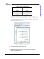
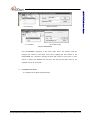
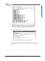
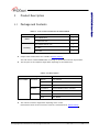
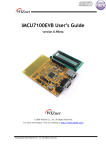
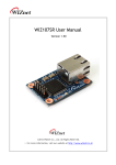
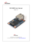
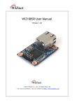
iMCU7100EVB User’s Guide Version 1.1 © 2011 WIZnet Co.,Ltd. All Rights Reserved. For more information, visit our website at http://www.wiznet.co.kr © Copyright 2011WIZnet Co.,Ltd. All rights reserved. 1 2 3 Overview ................................................................................................... 3 1.1 Introduction ................................................................................... 3 1.2 Specification .................................................................................. 4 Getting Started ........................................................................................... 5 2.1 Power On ...................................................................................... 5 2.2 Ping Test ....................................................................................... 5 2.3 Programming .................................................................................. 6 2.4 TCP Server Demonstration. ................................................................. 6 Product Description .................................................................................... 10 3.1 Package and Contents ..................................................................... 10 3.2 Board Layout ................................................................................ 11 3.3 Hardware Description ..................................................................... 12 3.4 Physical Specification ..................................................................... 16 © Copyright 2011 WIZnet Co.,Ltd. All rights reserved. Ver. 1.0 2 iMCU7100EVB User’s Guide Table of Contents Overview iMCU7100EVB is an Evaluation Board where the function and performance of W7100A can be tested. In this document, basic ping and TCP serer test will be tested. 1.1 Introduction iMCU7100EVB is an Evaluation Board made for testing whole functions of internet embedded MCU W7100A. iMCU7100EVB can easily build serial-to-Ethernet communication environment by using RS232 port and LAN port; W7100A can also use supported Character LCD and other added ports to control and test the all functions of the W7100A chip. The list of Application notes from WIZnet website is as followed. TCP server, client UDP DHCP DNS client DDNS HTTP server, client Telnet Serial to Ethernet server, client, UDP IPRAW MACRAW UART Timer LCD I2C © Copyright 2011 WIZnet Co.,Ltd. All rights reserved. Ver. 1.0 3 iMCU7100EVB User’s Guide 1 Specification <Table 1.1> Lists of Items Contained in the EVB Item MCU Memory Details Internet Embedded MCU - W7100A Note 8051 compatible 64KBytes Data Memory (RAM) 64KBytes Code Memory (ROM) Embedded in W7100A 2KBytes Boot code Memory 256Bytes Data Flash Serial Ethernet On board RS-232C 1Port with DB9 Connector On board RJ-45 with Transformer LCD 16Character * 2Line Character LCD LED General purpose LED 3Ea Network Status LED 8Ea Button Debugger Expansion Port Reset Switch 1Ea On board Debugger Socket MCU port expansion - 32Pin (8pin * 4) 2.54mm Pitch Pin-Header Hole - 14Pin (7pin * 2) 2.54mm Pitch Pin-Header Hole - 32Pin (8pin * 4) 2.00mm Pitch Pin-Header Hole - 14Pin (7pin * 2) 2.00mm Pitch Pin-Header Hole Dummy Hole Power - 167Pin 2.54mm Pitch Dummy Hole - 236Pin 2.00mm Pitch Dummy Hole DC 5V / 2A Adapter © Copyright 2011 WIZnet Co.,Ltd. All rights reserved. Built-in Ver. 1.0 4 iMCU7100EVB User’s Guide 1.2 Getting Started 2.1 Power On iMCU7100EVB User’s Guide 2 Connect Character LCD, UTP cable, RS-232C, and the power cable to the iMCU7100EVB. <Fig. 2.1> iMCU7100EVB Power on the iMCU7100EVB board, and check the following. 1. Check whether POWER LED(D13) is ON. 2. Check whether “iMCU7100 EVB” and “192.168.001.002” appears on the Character LCD. If the above two are checked iMCU7100EVB board is normally working. Ping Test 2.2 Run the command prompt at thetest PC, and execute the ping command to the IP of the test PC. Send the ICMP ping request and check the ICMP ping reply from the PC. Note: the test PC and the iMCU7100EVB board must be placed on the same sub-network. 1. Confirm the network information of Test PC as the following Source IP Address : 192.168.1.xxx Gateway IP Address : 192.168.1.1 Subnet Mask : 255.255.255.0 2. Execute ping command as the following “C:\> ping 192.168.1.2” © Copyright 2011 WIZnet Co.,Ltd. All rights reserved. Ver. 1.0 5 iMCU7100EVB User’s Guide <Fig 2.2> Ping test 2.3 Programming The iMCU7100EVB uses the WizISP program or W7100A debugger to program the compiled binary image(firmware). Please refer to the WizISP program guide and W7100A debugger guide for more detailed information. 2.4 TCP Server Demonstration The document for TCP server application note and the sample code are included in the bundle CD. The application note can also be downloaded from the WIZnet website. User can easily test the TCP loopback server demonstration by using the sample code. Lets test a simple TCP server demonstration as followed. 1. 2. 3. Confirm the testing environment. o Connect test PC to iMCUW7100EVB by using UTP cable directly. o Connect test PC to iMCUW7100EVB by using Serial able directly. o Connect 5V power adaptor to test PC Confirm the network information of test PC as fallows o Source IP Address : 192.168.0.2 o Gateway IP Address : 192.168.0.1 o Subnet Mask : 255.255.255.0 After executing serial terminal program (ex: HyperTerminal), set up the properties as followed. © Copyright 2011 WIZnet Co.,Ltd. All rights reserved. Ver. 1.0 6 iMCU7100EVB User’s Guide <Table 2.1> Setting of Terminal program Properties Setting Value Bits Per second (Baud Rate) 115200 bps Data Bits 8 Bits Stop Bits 1 Bits Parity No Flow Control None The serial message that indicates the operation of the TCP server is shown on the HyperTerminal. In order to check serial messages, the settings for HyperTerminal connection information must be done as shown in Figure 2.3. Check the COM port since it differs depending on the user‟s settings. <Fig 2.3> Setting of HyperTerminal program 4. Turn on the iMCU7100EVB and check the power LED. 5. Run AX1 as in the order below. (Please refer to AX1 user‟s manual for more details) Execute AX1 as shown in Fig 2.4 © Copyright 2011 WIZnet Co.,Ltd. All rights reserved. Ver. 1.0 7 iMCU7100EVB User’s Guide (a) Connecting (b)set IP and Port (c) Send data (d) set data format <Fig 2.4> Execute AX1 Since iMCU7100EVB is operating in TCP server mode, select „TCP Connect‟ from AX1 program and connect to the board. Enter the IP address and Port number of the iMCU7100EVB; the „connected‟ message will show and connect to TCP server. If „send‟ button is clicked, the loopback test will start. The data size and base value for the loopback test can be set by user. 6. Loopback server Result (a) Loopback server Result (HyperTerminal) © Copyright 2011 WIZnet Co.,Ltd. All rights reserved. Ver. 1.0 8 iMCU7100EVB User’s Guide <FIG 2.5>Result of LOOPBACK server Demonstration on HyperTerminal (b) Loopback server Result(AX1) <Fig 2.6> Result of LOOPBACK server Demonstration on AX1 If the loopback test successfully starts, the message that was sent from AX1 to iMCU7100EVB will be sent back to AX1. Continuous loopback test can be operated if user wishes to. © Copyright 2011 WIZnet Co.,Ltd. All rights reserved. Ver. 1.0 9 Product Description 3.1 Package and Contents iMCU7100EVB User’s Guide 3 <Table> 3.1 List of items contained in the iMCU7100EVB Item Board Accessory Quantity iMCU7100EVB Board 1 16 x 2 Character LCD 1 Power adapter (DC 5V / 2A) 1 UTP Cable 1 Serial Cable 1 Sample codes and documents are available on WIZnet website. The H/W version of iMCU7100EVB board can change for performance/function improvement. The fine parts of the component might differ depending on the manufacturer. <Table> 3.2 Web Contents Directory iMCU7100EVB Documents Hardware Software Contents Manual User‟s Manual Datasheet Datasheet of Main Parts App Note Application Notes Schematics iMCU7100EVB Hardware Schematic Parts List iMCU7100EVB Parts List Firmware iMCU7100EVB Firmware Tools AX1, WizISP The content of software might differ depending on the version. Download the latest version of firmware, software, and documents at WIZnet website. © Copyright 2011 WIZnet Co.,Ltd. All rights reserved. Ver. 1.0 10 iMCU7100EVB User’s Guide Board Layout 3.2 <Fig 3.1> Layout of iMCU7100EVB The description of each Part is shown inthe Table 3.3 is as below. <Table 3.3> Parts Description of iMCU7100EVB No Description No Description 1 WIZnetiMCUW7100A 2 RJ-45 Jack (integrated transformer) 3 RS-232C DB9 Connector 4 RS-232C 3Pin Header Hole (TTL) 5 DC 5V / 2A Adapter Jack 6 Power Switch 7 Reset Switch 8 Enable Boot Switch 9 PHY mode selection Switch 10 W7100ADebugger Connector 11 User LED * 3Ea 12 Network Status Indicate LED * 8Ea 13 Character LCD Connector 15 MCU Port Expansion Pin Header Hole 14Pin (7pin * 2) 2.54mm Pitch 17 19 MCU Port Expansion Pin Header Hole 32Pin (8pin * 4) 2.00mm Pitch 14 16 18 MCU Port Expansion Pin Header Hole 32Pin (8pin * 4) 2.54mm Pitch MCU Port Expansion Pin Header Hole 14Pin (7pin * 2) 2.00mm Pitch Dummy Pin Header Hole 236Pin 2.00mm Pitch Dummy Hole Dummy Pin Header Hole 167Pin 2.54mm Pitch Dummy Hole © Copyright 2011 WIZnet Co.,Ltd. All rights reserved. Ver. 1.0 11 Hardware Description iMCUW7100A (U1) The W7100A is the one chip solution that includes a hardwired TCP/IP core and an 8-bit internet microcontroller unit (iMCU), which is 100% compatible to standard embedded 8051 compatible MCU core.Please refer to the W7100A datasheet for more detailed information. Ethernet Port (P1) Ethernet Port (P1) is the connector that connects the UTP cable; and the RJ-45 connector internally includes a transformer to connect iMCU7100EVB board to the network. RS-232C Serial Port (P2, J11) RS-232C Serial Port (P2, J11) is a serial interface supported by W7100A. RS-232C Serial Port is basically structured to use DSUB 9Pin Male type connector (P2). But the RS-232C Serial Port is also structured to independently connect three pins of TX/RX/GND which are TTL signals, with the Pin header; allowing the user to use user-produced cable. Fig 2.2 shows the structure. <Fig 3.2> Simple RS-232C Serial Port DC Power Input Connector (DC1) DC Power Input Connector (DC1) is supported by 5V/2A Adaptor of iMCU7100EVB. DC Power Input Connector (DC1) is structured for a safe and stable environmentby applying Poly_Fuse(F1); to prevent board damage from excessive electric current caused from misusing the adaptor. Power Switch (SW1) Power Switch (SW1) is a Toggle switch for turning on/off DC. Reset Switch (SW2) Reset Switch (SW2) is for manual reset to provide users the ability to reset whenever they want (ex: during the system is running). Boot Enable Switch (SW3) Boot Enable Switch (SW3) is used to select the W7100A booting mode and provides the © Copyright 2011 WIZnet Co.,Ltd. All rights reserved. Ver. 1.0 12 iMCU7100EVB User’s Guide 3.3 iMCU7100EVB User’s Guide following modes. <Table 3.4> Description of Boot Enable switch SW3 Description On Boot Enable. To program by using the WIZISP Off Boot Disable. To run the application programmed by the WIZISP PHY Mode Switch (SW4) PHY Mode Switch(SW4) is for setting the mode of PHY block inside W7100A.PHY Mode Switch(SW4) provides the following modes. <Table 3.5> Description of PHY Mode selection switch SW4 Mode Description 1 2 3 OFF OFF OFF Auto OFF OFF ON A100 Auto-negotiation with 100 BASE-TX FDX/HDX ability OFF ON OFF A10 Auto-negotiation with 10 BASE-T FDX/HDX ability OFF ON ON - ON OFF OFF 100F Manual selection of 100 BASE-TX FDX ON OFF ON 100H Manual selection of 100 BASE-TX HDX ON ON OFF 10F Manual selection of 10 BASE-T FDX ON ON ON 10H Manual selection of 10 BASE-T HDX Normal Operation Mode Auto-negotiation enable with all capabilities Reserved W7100A Debugger Connector (JP2) W7100A Debugger Connector (JP2) is for monitoring and changing various registers and internal memory inside W7100A. User can write applications in the Code memory, therefore allowing efficient debugging of software made by user. <Figure 3.3> W7100A Debugger Connector Please refer to W7100A Debugger Guide for more details on W7100A Debugger. © Copyright 2011 WIZnet Co.,Ltd. All rights reserved. Ver. 1.0 13 iMCU7100EVB User’s Guide General purpose LEDs There are three User LEDs for the user to control/test the Port and Debugging. <Table 3.6> Description of User debugging LED LED Name W7100A Pin Name Direction LED0 P0_3 O LED1 P0_4 O LED2 P0_5 O Network Status Indicate LEDs Table 3.7 lists the descriptions for Indicate LEDs that tell the network status. <Table 3.7> Description of Status indicate LED LED Name W7100A Pin Name DIR. 10/100 SPDLED O Description Network speed indicate LED Low : 100Mbps , High : 10Mbps FDX FDXLED O Full / Half duplex indicate LED Low : Full duplex , High : Half duplex COL COLLED O Collision detect LED Low : Collisions occurred (only in half duplex mode) RX RXLED O Active Low. Receive activity LED TX TXLED O Active Low. Transmit activity LED LINK LINKLED O Active Low. Network link status indicate LED ACT ACTLED O Active Low. Rx or Tx activity LED PLOCK PLOCK O Active High. It notifies when internal PLL is locked. Character LCD Connector (JP1) Character LCD Connector (JP1) is for Debugging and showing the system status.Pin descriptions of the Character LCD Interface are as followed. <Table 3.8> Character LCD Interface Pin Description PIN# iMCU7100EVB Board PIN NAME / Character LCD PIN NAME DIR. Description 1 GND / VSS 2 5V / VDD I LCD Power Supply 3 V0 / V0 I Voltage for LCD drive 4 P0_0 / RS I Data / Instruction register select 5 P0_1 / RW I Read / Write © Copyright 2011 WIZnet Co.,Ltd. All rights reserved. Signal Ground Ver. 1.0 14 P0_2 / E 7 ~ 14 I P2_0 ~ P2_7 / DB0~ DB7 I/O Enable signal,start data read / write Data Bus Line 15 Not Connect / LED A O LED Anode, power supply+ 16 Not Connect / LED K O LED Cathode,ground 0V iMCU7100EVB User’s Guide 6 Please refer to LCD Datasheet (LC1624-R2.pdf) for more details on driving Character LCD. MCU Port Expansion Pin header Hole (J1 … J10) W7100A provides two types of pitches from the total of 32pin (8bit x 4Port) IO pin. User can select according to their needs between 2.54mm Pin pitch and 2.00mm Pin pitch. iMCU7100EVB board provides four ports of IO to allow users to use with the general pin header.The description of port expansion is as followed. <Figure 3.4> Port Expansion Connector Dummy Pin Header Hole Dummy pin header holes are not connected with system circuits. The dummy pin header hole is provided into two types: 2.54mm Hole pitch and 2.00mm Hole pitch. By using dummy hole, users can test external devices that are in need of additional tests. © Copyright 2011 WIZnet Co.,Ltd. All rights reserved. Ver. 1.0 15 iMCU7100EVB User’s Guide 3.4 Physical Specification <Figure 3.5> iMCU7100EVB Dimension <Table 3.9> iMCU7100EVB Board Dimension Symbols Dimensions (mm) Symbols Dimensions (mm) A 129.2 F 31.1 B 37.2 G 2.7 C 12.6 H 9.4 D 15.9 I 8.3 E 3.6 J 83.6 © Copyright 2011 WIZnet Co.,Ltd. All rights reserved. Ver. 1.0 16 iMCU7100EVB User’s Guide Document History Information Revision Ver. 0.9 Data Aug 17, 2009 Ver. 1.0 May 12, 2011 Description Beta release Modified and added contents with iMCU7100EVB Rev. 1.1 lunching Copyright Notice Copyright 2011 WIZnet Co.,Ltd. All Rights Reserved. Technical Support: [email protected] Sales & Distribution: [email protected] For more information, visit our website at http://www.wiznet.co.kr © Copyright 2011 WIZnet Co.,Ltd. All rights reserved. Ver. 1.0 17