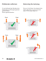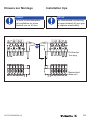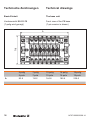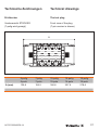
1
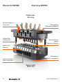
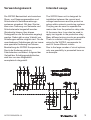
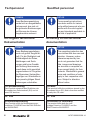
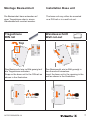
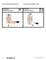
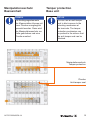
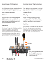
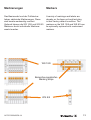
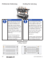
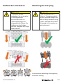
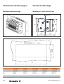
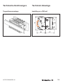
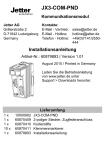
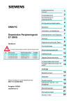
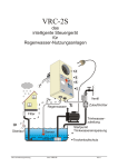
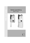
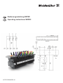
 Bedienungsanleitung WIPRO
Operating instructions WIPRO
1470710000/00/08.14
Übersicht WIPRO
Overview WIPRO
Prüfstecker
Test plug
Prüfanschlüsse
Test ports
Entriegelung
Release mechanism
Kodierstifte
Coding pins
Manipulationsschutz
Tamper protection
Markierung
Marking
Befestigung
Attachment mechanism
Leiteranschluss
Wire connection
Basiseinheit
Base unit
2
1470710000/00/08.14
Verwendungszweck
Intended usage
Die WIPRO Basiseinheit wird zwischen
Strom- und Spannungswandlern und
Schutzrelais in Netzüberwachungssystemen eingebaut. Mit dem Stecker
kann eine Trennung von Netzseite und
Schutzrelaiseite hergestellt werden.
Gleichzeitig können über diesen
Testsignale an die Schutzrelais angelegt
werden. Dabei gibt es eine Vielzahl von
Schaltungen welche möglich sind. Für die
verschiedenen Schaltungen gibt es immer
eine spezielle Kodierung und interne
Beschaltung der WIPRO Komponenten.
Durch die Kodierung wird ein
Falschstecken verhindert. Aufgrund der
Vielzahl der Schaltungsmöglichkeiten,
wird hier nur eine Möglichkeit
exemplarisch dargestellt.
The WIPRO base unit is designed for
installation between the current and
voltage transformers and the protective
relays within network monitoring systems.
The plug can be used to separate the
mains side from the protective relay side.
At the same time it can also be used to
apply test signals to the protective relay.
Many different wiring circuits are possible.
There is a distinct coding and internal
wiring for the WIPRO components for
each of these different circuits.
Due to the large number of circuit options,
only one possibility is presented here as
an example.
IN
I L1
1470710000/00/08.14
I L2
I L3
3
Sicherheitsmaßnahmen
WARNUNG
Lesen sie vor Verwendung
von WIPRO das
Bedienungsanleitung durch
und befolgen sie die darin
enthaltenen Hinweise.
Benutzen sie WIPRO nicht
mit höheren Strömen oder
Spannungen als die
zugelassenen Grenzwerte.
Sollten die Prüfstecker und
Basismodule beschädigt
werden, dürfen diese nicht
selbst repariert werden. Ein
demontieren oder umbauen
der Prüfstecker und
Basismodule ist nicht
zulässig. Der Prüfstecker darf
während des Einsatzes im
Anlagenbetrieb nur wie in der
Bedienungsanleitung
beschrieben eingesetzt
werden.
WARNUNG
Während der Prüfung ist
darauf zu achten, die
Kontaktstreifen des
Prüfsteckers nicht mit den
Fingern zu berühren, da
durch die Verkabelung zum
Testgerät oder der
Schutzeinheit Spannung
besteht.
4
Safety precautions
CAUTION
Read and follow the entire
operating instructions before
using the WIPRO. Never use
the WIPRO with current or
voltage that is higher than
the permissible limits. Do not
attempt to repair the test plug
or base module yourself if
these get damaged. You may
not take apart or otherwise
convert the test plug or base
module. The test plug may
be put into use during system
operation only in the way
described in the operating
instructions.
CAUTION
At any stage in handling of
the test plugs care must be
taken not to make contact
with test plug-fingers as they
may be connected to live
equipment either via the test
block or test equipment.
1470710000/00/08.14
Bestimmungsgemäßer
Gebrauch
Approved use
HINWEIS
NOTICE
Das Gerät ist nur für die in
der Bedienungsanleitung
beschriebenen
Anwendungen bestimmt.
Eine andere Verwendung
ist unzulässig und kann zu
Unfällen oder Zerstörung
des Gerätes führen. Diese
Anwendungen führen zu
einem sofortigen Erlöschen
jeglicher Garantie- und
Gewährleistungsansprüche
des Bedieners gegenüber
dem Hersteller.
This device is intended
for use in applications as
described in the operating
instructions only. Any
other form of usage is not
permitted and can lead to
accidents or destruction of
the device. Using the device
in non-approved applications
will lead immediately to the
expiry of all guarantee and
warranty claims on the part
of the operator against the
manufacturer.
WARNUNG: Gefahrenstelle
Ein Einsatz des ausgewählten Produktes
außerhalb der Spezifikation oder Missachtung
der Bedienhinweise und
Warnhinweise kann zu
folgenschweren Fehlfunktionen derart führen, dass
Personen bzw. Sachschaden entstehen kann.
1470710000/00/08.14
CAUTION: Danger
Using the selected device
for purposes other than
those specified or failure
to observe the operating
instructions and warning
notes can lead to serious
malfunctions that may result
in personal injury or damage
to property.
5
Fachpersonal
Qualified personnel
HINWEIS
NOTICE
Diese Bedienungsanleitung
wendet sich an ausgebildetes
Fachpersonal, das sich mit
den geltenden Bestimmungen
und Normen des Verwendungsbereichs auskennt.
These operating instructions
have been written for trained
and qualified personnel who are
familiar with the valid regulations and standards applicable to
the field of application.
Richtigkeit technische
Dokumentation
Accuracy of the technical
documentation
HINWEIS
NOTICE
Diese Bedienungsanleitung
wurde mit großer Sorgfalt erstellt. Für die Richtigkeit und
Vollständigkeit der Daten,
Abbildungen und Zeichnungen wird keine Gewähr
oder Haftung übernommen,
soweit diese nicht gesetzlich
vorgeschrieben ist. Es gelten
die Allgemeinen Verkaufsbedingungen von Weidmüller in
ihrem jeweils gültigen Stand.
Änderungen vorbehalten.
This operating instruction has
been written with due care and
attention. However, unless
otherwise required by law
we do not guarantee that the
data, images and drawings
are accurate or complete nor
do we accept liability for their
contents. Weidmüller’s general
terms and conditions of sale
apply in their respective valid
form. Subject to alteration
without notice.
CE-Kennzeichnung
CE Mark
UL 1059
UL 1059
Konformitätserklärung
Declaration of conformity
Das Produkt entspricht den Richtlinien der
Europäischen Gemeinschaft (EU) und ist
somit CE konform.
Das Produkt erfüllt die Niederspannungsrichtlinien 73/23/EWG und die EMV-Richtlinien 89/336/EWG.
6
This product fulfils the guidelines issued by the
European Union (EU) and is therefore entitled
to carry the CE mark.
The product fulfils both the Low
Voltage Directive 73/23/EEC and the
EMC Directive 89/336/EEC.
1470710000/00/08.14
Montage Basiseinheit
Installation Base unit
Die Basiseinheit kann entweder auf
einer Tragschiene oder in einem
Wandausschnitt montiert werden.
The base unit may either be mounted
on a DIN rail or in a wall cut-out.
Wandausschnitt
Wall cut-out
Materialdicke = 1…3 mm
54.8
Tragschiene
DIN rail
A
Top
2
1
2
1
Das Basismodul wie im Bild gezeigt auf
die Tragschiene aufrasten.
Snap on the base unit to the DIN rail as
shown in the illustration.
3
4
0.5 - 0.6 Nm
1470710000/00/08.14
Das Basismodul wie im Bild gezeigt in
den Ausschnitt einsetzen.
Insert the base unit in the opening in the
wall as shown in the illustration.
3
4
0.5 - 0.6 Nm
7
Anschluss Basiseinheit
Zugbügel
Clamping yoke
Connections Base unit
Zugfeder
Tension clamp
0.8 Nm
8
1470710000/00/08.14
Manipulationsschutz
Basiseinheit
Tamper protection
Base unit
HINWEIS
NOTICE
Die Betätigungselemente
der Klemmstellen können mit
einer Plombe unzugänglich
gemacht werden. Dazu wird
der Manipulationsschutz zur
Seite geschoben und eine
Plombe montiert.
You can use an anti-tamper
seal to block access to the
actuating mechanism at
the terminals. The tamper
protection mechanism can
be pushed to the side so that
the anti-tamper seal can be
attached.
Manipulationsschutz
Tamper protection
Plombe
Anti-tamper seal
1470710000/00/08.14
9
Anschluss Prüfstecker
Connections The test plug
Am Prüfstecker können an jedem Kontakt
zwei Kabel angeschlossen werden.
Jeweils eins mit einem Prüfstecker und
eins mit einem Kabelschuh.
Two cables can be connected to the test
plug at each contact. One is connected
with a test plug and one is connected
using a cable lug.
PS4 Stecker
PS4 plug
Ein PS4 oder PS4–Sicherheitsstecker
(MC-Sicherheitsstecker „MAH 558 /
XZGL-425“ oder baugleiche Stecker)
kann auf den Prüfstecker wie im Bild
gezeigt aufgesteckt werden.
A PS4 plug or PS4 safety plug (MC
safety plug „MAH 558 / XZGL-425“ or
compatible plug) can be attached to the
test plug as shown in the illustration.
Kabelschuh
Es können Ring- oder Gabelkabelschuhe
verwendet werden. Dazu müssen
zuerst die Prüfsteckerbuchsen mit
einem Schraubendreher gelöst werden.
Anschließend der Kabelschuh seitlich
in den Prüfstecker eingeführt, und die
Buchse wieder angeschraubt werden.
Cable lug
Ring-shaped or forked lugs may be used.
First you should use a screw driver to
disconnect the test-plug socket. Then
insert the cable lug sideways into the test
plug and screw the socket back on.
0.5 Nm
Ring- und Gabelkabelschuhe
der Größe M3 verwenden.
Use size M3 ring lugs and
forked cable lugs.
10
1470710000/00/08.14
Markierungen
Markers
Das Basismodul und der Prüfstecker
haben zahlreiche Markierungen. Diese
sind bereits werksseitig montiert.
Optional können die WS 10/8 und WS 8/5
Markierer durch individuelle Markierer
ersetzt werden.
A variety of markings and labels are
already on the base unit and test plug
in their factory-default condition. The
markers on the WS 10/8 and WS 8/5 can
be optionally replaced with customised
markers.
WS 10/8
Bezeichnungsstreifen
Marking strips
WS 8/5
1470710000/00/08.14
11
Prüfstecker Kodierung
Coding the test plug
HINWEIS
NOTICE
Die Kodierung des Steckers
und der Basiseinheit verhindert, dass ein Stecker verdreht oder auf eine falsche
Basiseinheit gesteckt werden
kann. Die Kodierungen sind
so ausgelegt, dass kein
falsches Stecken möglich ist.
Jede Variante hat ihre eigene
Kodierung.
When the plug and the base
unit are coded to match, it will
not be possible to insert the
plug upside down or insert the
plug into the wrong base unit.
The coding is designed so that
it is impossible to insert the
plug incorrectly. Each variant
has its own unique coding.
One of the four coding
elements is
Um die Orientierung beim
Stecken zu erleichtern ist
eines der vier Kodierelemente orange ausgeführt.
coloured orange; this helps the
user to properly align the plug
while it is being connected.
Beispielkodierung
coding example
12
1470710000/00/08.14
Prüfstecker aufstecken
WARNUNG
Prüfstecker gerade
einstecken, bis er einrastet.
Ein Schrägstecken
des Steckers kann zu
Fehlkontaktierungen im
Anlagenbetrieb führen, die
Schäden an der Anlage
oder am Testgerät zur Folge
haben können.
Attaching the test plug
CAUTION
Push the plug on until it
clicks in. Connectors which
are not inserted straight can
lead to faulty contacts during
system operation and result
in damage to the system or
test instrument.
✓
✓
✗
✗
Automatische selbsttätige Verriegelung
Automatic locking
1470710000/00/08.14
13
Prüfstecker entfernen
Removing the test plug
Vor und während des Abziehens des
Prüfsteckers die Entriegelungstasten
gedrückt halten.
Stecker gerade abziehen.
Be sure to hold down the release button
before and while you pull out the test
plug. Pull the plug straight out.
Push
Push
✗
✓
Push
Push
✓
14
✗
✗
1470710000/00/08.14
Hinweis zur Montage
Installation tips
HINWEIS
NOTICE
Für eine leichte Bedienbarkeit empfehlen wir einen
Abstand von ca. 40 mm.
We recommend maintaining
an approximately 40 mm gap
to improve accessibility.
Prüfstecker
Test plug
21
Basiseinheit
Base unit
1470710000/00/08.14
15
Technische Zeichnungen
Technical drawings
Basis Einheit
The base unit
Vorderansicht BASIS ZB
(7-polig wird gezeigt)
Front view of the ZB base
(7-pin version is shown)
71.8
A
A
16
5-polig
5-pole
7-polig
7-pole
10-polig
10-pole
14-polig
14-pole
19-polig
19-pole
93.8
114.2
144.8
185.6
236.6
1470710000/00/08.14
Technische Zeichnungen
Technical drawings
Prüfstecker
The test plug
Vorderansicht STECKER
(7-polig wird gezeigt)
Front view of the plug
(7-pin version is shown)
A
A (mm)
5-polig
5-pole
7-polig
7-pole
10-polig
10-pole
14-polig
14-pole
19-polig
19-pole
135,8
156,2
186,8
227,6
278,6
1470710000/00/08.14
17
Technische Zeichnungen
Technical drawings
Wandausschnittmontage
Installing in a wall cut-out hole
44
47
66
73
66
73
1– 3
39
47
54.8
Materialdicke = 1…3 mm
A
A
18
5-polig
5-pole
7-polig
7-pole
10-polig
10-pole
14-polig
14-pole
19-polig
19-pole
94,9
115,3
145,9
186,7
237,8
1470710000/00/08.14
Tragschienenmontage
Installing on a DIN rail
66
Technical drawings
73
Technische Zeichnungen
44
1470710000/00/08.14
47
19
Weidmüller Interface GmbH & Co. KG
Postfach 3030
D-32720 Detmold
Tel. +49 5231 14-0
Fax +49 5231 14-2920 83
[email protected]
www.weidmueller.com
20
1470710000/00/08.14