1
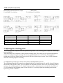
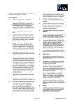
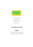
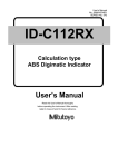
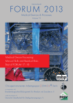
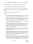
PKP Prozessmesstechnik GmbH
Borsigstrasse 24
D-65205 Wiesbaden-Nordenstadt
Tel: 06122 / 7055 - 0
Fax: 06122 / 7055 – 50
Operating Instructions
PS12
Electronic miniature pressure switch
Contents
1 Introduction
2
2 Safety Information
2
3 Electrical Connection
3
4 Adjusting the Switching Point
3
5 Maintenance
4
6 Specifications: See data sheet in the appendix
1 Introduction
Series PS12 pressure switches are noted for their reliable function and easy operation.
To obtain the greatest benefit from this device, please observe the following cautionary
statement:
Persons who are responsible for setting up or operating this device must be sure to read
the and understand the operating instructions and the safety information pertaining to
it.
2 Safety Information
2.1 General Instructions
To ensure safe operation, the device must only be operated according to the information in the
operating instructions. When the device is in use, the regulations and safety standards
applicable to the specific application must also be observed. This statement also applies to the
use of accessories.
2.2 Proper Usage
Series PS12 are designed to transform a pressure into one or two electrical output signals.
Any application extending beyond this specific intended use does not constitute proper usage.
Series PS12 pressure switch must not be employed as the sole means of avoiding hazardous
conditions in machinery and installations.
The machinery and installations must be designed in such a manner that faulty conditions and
malfunctions will not present hazardous situations for operating personnel.
2.3 Qualified Personnel
Series PS12 must only be used by qualified, knowledgeable personnel trained in correct use
of these devices. Qualified personnel are those persons familiar with setting up and
assembling these devices, placing them in service and operating them. In addition, such
personnel must also be qualified to perform the work associated with the application for
which the device is being used.
PS12-E~1.SAM
03.05.05
Page 2
3 Electrical Connection
Round plug connector M12x1 (4-pin)
P-switching / N-switching
Cable outlet
P-switching / N-switching
M12x1
Cable outlet
Power supply
UB
1
brown
0V
0V
3
blue
Switching output
SA1
4
black
Switching output
SA2
2
white
4 Adjusting the switching point
The switching point is adjusted with the system under pressure. The switching point is adjusted with setting
screw as follows:
Turn the setting screw clockwise to increase the switching point. The setting screw is self-locking and does
not have to be secured against turning. The torque applied should not exceed 30 Nm. The integrated
switch-status LEDs are located in the lower part of the black plastic upper section. These LEDs illuminate
when the switching output is occurring.
4.1 Adjustment procedure for variants: NC contact with adjustable hysteresis
The switching point and the hysteresis are adjusted with the two setting screws S1 and S2. Screw S2 adjusts
the switch for the pressure value; screw S1 adjusts the maximum pressure value. If the S2 switching point is
set above the switching point for S1, then the output acts like a normal pressure switch with a hysteresis of
5%. S2 determines the switching point; S1 has no effect. To correctly adjust the switching point and the
hysteresis, proceed as follows:
PS12-B~1.SAM
03.05.05
Page 3
1. Turn the S2 setting screw counter-clockwise all the way to the left-hand stop
(minimum).
2. Turn the S1 setting screw clockwise all the way to the right-hand stop (maximum).
3. Apply the switching point pressure to the pressure switch in a test system.
4. Turn the S1 setting screw counter-clockwise to adjust the switching point.
5. Set the pressure for the lower switching point.
6. Turn the S2 setting screw clockwise to adjust the hysteresis.
Caution: The leads for pressure switches with M12x1 plug connectors must not have any
integrated LEDs.
5 Maintenance
Mechanical pressure switches are maintenance-free.
The measuring accuracy (as per DIN EN 837) of the pressure switch should be checked
regularly. Testing or recalibration must be performed only by trained personnel with suitable
equipment.
Caution:
When working with hazardous media such as oxygen, acetylene, combustible materials or
poisonous materials and when working on refrigeration systems, compressors, etc.:
In addition to generally accepted safe practices, all applicable regulations must be observed.
Be sure to take proper precautions during maintenance work.
PS12-E~1.SAM
03.05.05
Page 4