Transcript
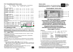
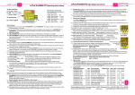
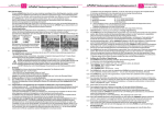
Page
1e
Issue 05.06
LiPoBalancer Operating Instructions, Software V8 and later
8 / 14 red cell-count-LEDs
indicate balancing process
Safety circuit is active
(conductive) when green
„EIN“-LED is glowing
Safety-sockets for loopedthrough charge lead.
„+“ charge lead (red)
to be connected there.
Display of the Battery type
LiPoBalancer Supplement mainly for PCB version with
pushbutton
Schulze BalCab20
balancer-socket
for 2s ... 8s packs
resp. 2s ... 14s packs.
Of course ideal for
Schulze LiPoPerfekt
battery packs.
RS232 - interface (COM - port)
for exporting charge data and
importing firmware updates.
Schulze BalCab10 balancer socket for 2s ... 4s packs.
Ideal for Schulze LiPoPerfekt
battery packs.
2e
Press the button exactly when the LED matching your battery type lights up.
The selected type will be indicated for a period of three seconds.
The normal POWER ON indicator (moving strip etc.) is then displayed, and the balancer carries out its
work.
2
Additional push-button functions
If the unit stops balancing because a limit value is exceeded, and the safety circuit has been triggered, the
balancer displays the reason for the shut-down (over-voltage, under-voltage, etc.).
After this it “goes to sleep” completely in order to save current - but it can be woken again with a brief press
on the button.
Alternatively, if you hold the push-button pressed in for two seconds to wake it up, the usual POWER ON
procedure is followed by a display of flashing error-code LEDs: the flashing LEDs are those which exceeded the limit value, and which resulted in the shut-down before the balancer went to sleep. This does not
apply if the LiPoBalancer detects that the battery has in the meantime been replaced by another pack with
a different distribution of cell voltages.
If the condition which led to the shut-down still persists, the balancer will again go to sleep after one minute; otherwise it resumes working.
If you hold the button pressed in for two seconds in normal use, the LiPoBal goes to sleep - which also causes the
integral safety circuit to be isolated.
Note: the current circuit board with the “battery type selection by push-button” draws less current when “asleep”
compared to the earlier “jumper” model: only 1 … 6 mA “sleep current”, according to the cell count connected to it.
3
Conventional
balancer - socket
7-pin JST connector
for 2s ... 6s packs
Graupner- and
Robbe compatible
Issue 05.06, Page
1.3.4
This cable must be
plugged into the „+“
socket on the battery charger.
When using the
conventional
balancing connector:
Battery type select
by push-button:
Li-Po, Li-Io
Li-Fe, Nickel
(resp. as configured via RS232)
Operating Instructions
Universal socket (JST connector)
The socket for Graupner or Robbe battery packs has now moved to the front end of the circuit board.
Batteries consisting of up to six cells can be balanced using the 7-pin socket.
Please ensure that the negative terminal of the battery is connected to the outermost connecting pin on the
left (towards the edge of the circuit board - see also the text printed on the front panel).
Important: only ONE of the three balancer connectors may be used at any one time.
Connecting several packs simultaneously to the same or different sockets will cause damage to the
balancer.
8
New LED-Displays
When different errors occur then also different error messages are displayed. The corresponding LEDs
show the codes one after the other.
Dear customer,
In the course of product maintenance we have introduced some minor modifications to the LiPoBalancer.
Some parts of the original operating instructions are affected by this, and no longer apply.
All the differences are listed in this separate sheet, which is valid only for the version of the circuit board with a
push-button for battery type selection (NOT VALID (!) for the circuit board version with a jumper for battery
type selection - Exception: SetFilterOn/Off command).
Note: software updates automatically detect the circuit board version you are using.
BUT: software versions 1 to 6 must not (!) be loaded into the present circuit board version!!
1
Battery type setting
(only if a Schulze BalCab 10 or BalCab 20 balancer lead is not used)
1.1
The jumper has been replaced by a push-button, as the LiPoBalancer now supports four battery types.
1.2
Three LEDs are now used to indicate the jumper “setting”:
Blue = Li-Po
Orange = Li-Io
Yellow = Li-Fe (Saphion cells)
All off = Nickel (Ni-Cd, Ni-MH)
1.3
Set-up instructions battery type
1.3.1 Hold the push-button pressed in.
1.3.2 Connect the balancer lead.
All the LEDs light up; the balancing LEDS then go out.
1.3.3 Release the push-button.
The battery type LEDs cycle through all four states listed under 1.2 at one-second intervals.
8.4
The calibration of the Balancer got lost. All LEDs are flashing simultaneously.
You have to send the LiPoBalancer for a service to Weiterstadt.
8.5
More than 8 cells are connected to a LiPoBal 08. The balancer is not able to balance the pack.
The LED of the cell # 8 shows „missing cell“ (blinks 2 times; the balancer refuses to work).
8.6
At over-voltage of one or more cells the balancer does not go to sleep but the safety circuit is opened. The
green „EIN“-LED goes out. The balancing of the cells in the pack goes on; the high voltage decreases.
When 9.4.1.9 „SetFullSleep“ is set then the balancer goes to sleep after the battery is fully balanced.
9
New “SET” commands
9.4.1.9
SetFullSleep
Balancer goes to sleep when the voltage of the pack falls (charger has switched off) and the cells are no
longer being balanced.
9.4.1.10 SetFullAlive
Balancer only goes to sleep if cell limit values are exceeded, or if the push-button is held in for two full
seconds.
9.4.1.11 SetFilterOn - Also available on PCBs with the battery type selection jumper.
When a battery is charged with refresh-pulses then the caused voltage spikes are suppressed as good as
possible. For this reason it is possible to use the LiPoBalancer also connected to those chargers the
refresh-pulses can not be switched off.
9.4.1.12 SetFilterOff
The spike filter is switched of for a genuine voltage value output at a spike free charge/discharge.
Schulze Elektronik GmbH • Prenzlauer Weg 6 • 64331 Weiterstadt • Fon: +49-6150-1306-5, Fax: 1306-99
www.schulze-elektronik-gmbh.com
[email protected]
• Germany •