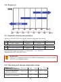
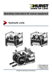
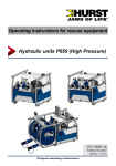
1
Operating instructions for rescue equipment
Hydraulic power unit P 630 SG
175070085 EN
Edition 11.2013
(Translation of the original operating instructions)
2
Content
Page
1. Danger classi¿cations
5
2. Product safety
6
3. Proper use
10
4. Power unit designation
11
5. Functional description
11
5.1
5.2
5.3
5.4
5.5
5.6
5.7
General information
Installation of the power unit
Motor
Valves
Pumps
Frame with side sections
Connection to the rescue equipment
6. Connecting the hoses / devices
11
12
13
14
15
15
15
16
6.1 Coupling the mono-couplings
16
7. Erection and start-up
18
7.1 Set-up
7.2 Start-up
18
18
8. Operation
20
8.1
8.2
8.3
8.4
20
21
21
22
Starting the engine
Turning the engine off
Refuelling
Controlling the valves
9. Dismantling the equipment / deactivation following operation
23
10. Tests
24
10.1 Recommended test intervals
10.2 Visual and function check
24
25
11. Maintenance and repair
26
11.1 General information
11.2 Service work on the hydraulic unit
11.3 Additional service work
26
27
29
12. Fault analysis
34
3
Content
Page
13. Technical data
13.1
13.2
13.3
13.4
13.5
13.6
13.7
13.8
39
Power unit
Noise emissions
Sparking plug
Sparking plug spanner
Fuel
Engine oil
Hydraulic fluid recommendation
Operating and storage temperature range
39
41
42
42
42
43
43
43
14. EC Declaration of Conformity
44
15. Notes
45
4
1. Danger classifications
We differentiate between various different categories of safety instructions. The table shown
below shows you an overview of the assignment of symbols (pictograms) and signal words
to the speci¿c danger and the possible consequences.
Persons
Damage /
injury to
Property
Pictogram
Key word
Definition
Consequences
DANGER!
Immediate danger
Death or severe
injury
WARNING!
Potentially
dangerous
situation
Potential death or
serious injury
CAUTION!
Less dangerous
situation
Minor or slight
injury
Danger of damage
to property/
environment
Damage to the
equipment,
damage to the
environment,
damage to
surroundings
ATTENTION!
-
NOTE
Handling tips and No injury/damage
other important/
to persons/
useful information
environment/
and advice
device
Wear a helmet with a face guard
Wear protective gloves
Wear safety shoes
Proper recycling
Protect the environment
Read and follow operating instructions
5
2. Product safety
LUKAS products are developed and manufactured to ensure the best performance and
quality when used as intended.
The safety of the operator is the most important consideration in product design. Furthermore,
the operating instructions are intended to help in using LUKAS products safely.
The generally applicable legal and other binding regulations pertaining to the prevention of
accidents and protection of the environment apply and are to be complied with in addition to
the operating instructions.
The equipment must only be operated by persons with appropriate training in the safety
aspects of such equipment – otherwise, there is a danger of injury.
We would like to point out to all users that they should read carefully the operating instructions
and the instructions contained therein before they use the equipment, and that they should
carefully follow such.
We further recommend you have a quali¿ed trainer show you how to use the product.
CAUTION!
The operating instructions for the hoses, accessories and the connected
devices must also be heeded!
Even if you have already received instruction on how to use the equipment, you should still
read through the following safety instructions again.
CAUTION!
Ensure that the accessories and connected equipment are suitable for the
maximum operating pressure!
Please ensure that no body
parts or clothing get stuck
between the visibly moving
parts.
Immediately report any changes
that occur (including changes
in operating behaviour) to
the appropriate persons/
departments! If necessary, the
equipment is to be shut down
immediately and secured!
Check the equipment for visible
Àaws or damage before and
after use.
Wear protective clothing, safety
helmet with visor, safety shoes
and protective gloves.
Working under suspended
loads is not permitted where
such loads are being lifted only
by means of hydraulic devices.
If this work is unavoidable,
suitable mechanical supports
are also required.
Check all lines, hoses and
screwed connections for leaks
and externally visible damage,
and repair immediately!
Escaping hydraulic Àuid can
cause injuries and ¿res.
6
In the event of malfunctions,
immediately deactivate the
device and secure it. Repair the
fault immediately.
Do not carry out any changes
(additions or conversions) to the
equipment without obtaining the
approval of LUKAS beforehand.
Observe all safety and danger
information on the device and in
the operating instructions.
All safety and danger
information on the device must
always be complete and in a
legible condition.
Please ensure that all safety
covers are present on the
equipment and that they are in
proper and adequate condition.
Any mode of operation which
compromises the safety and/
or stability of the device is
forbidden!
Safety devices must never be
disabled!
The maximum operating
pressure set on the equipment
must not be changed!
Make sure before switching
on/starting up the device and
during its operation, that this will
put no one in danger.
Observe all intervals for
recurring tests and/or
inspections that are prescribed
or stated in the operating
instructions.
When working close to live
components and cables,
suitable measures must be
taken to avoid current transfers
or high-voltage transfers to the
equipment.
Only original LUKAS
accessories and spare parts are
to be used for repairs.
The build-up of static charge
and therefore possible sparking
must be avoided when handling
the device.
Do not touch the engine and
exhaust system when running
with combustion engine pumps
because of the danger of
burning.
Motorised pumps must not be
operated in areas at risk of
explosion!
Combustion engines must not
be operated in enclosed spaces
because of the danger of
poisoning and / or smothering.
When working with this
equipment or when transporting
it, ensure that you do not get
caught up in the hose or cable
loops and trip.
7
If you spill any fuel when using
combustion engines, you
must remove the spilled fuel
completely before starting the
engine.
Keep combustion engines and
their fuels away from sources
of ignition since otherwise there
will be a danger of explosion.
Refuelling whilst the engine is
running is strictly prohibited!
In order to prevent the danger
of ¿re, you should ensure
adequate ventilation when
operating combustion engines
and you must keep a safety
distance of at least 1m (39.4 in.)
to walls and other screens.
Damage to electrical
components must only
be repaired by a quali¿ed
electrician in compliance with
all applicable national and
international safety guidelines
and regulations.
Make sure that the combustion
engines are always standing on
as Àat and horizontal a surface
as possible to prevent fuel from
leaking out.
When setting up the units, you
must make sure that they are
not impaired by the inÀuences
of extreme temperatures.
The equipment is ¿lled with
hydraulic Àuid. This hydraulic
Àuid can be detrimental to
health if it is swallowed or its
vapour is inhaled. Direct contact
with the skin must be avoided
for the same reason. Also,
when handling hydraulic Àuid,
note that it can negatively affect
biological systems.
When working with or storing
the equipment, ensure that the
function and the safety of the
equipment are not impaired
by the effects of severe
external temperatures or that
the equipment is damaged in
any way. Please note that the
equipment can also heat up
over a long period of use.
Make sure there is adequate
lighting while working.
Before transporting the
equipment, always ensure that
the accessories are positioned
in such a way that they cannot
cause an accident.
Always keep these operating
instructions easily accessible at
the place of operation.
Ensure the proper disposal of
all removed parts, leftover oil,
hydraulic Àuid and packaging
materials.
8
All damaged electrical
components e.g. scorched
cables, etc. are to be replaced
immediately!
The generally applicable, legal and other binding national and international regulations
pertaining to the prevention of accidents and protection of the environment apply and are to
be implemented in addition to the operating instructions.
WARNING/CAUTION!
The device is intended exclusively for the purpose stated in the operating instructions
(see chapter "Proper Use"). Any other use is not in accordance with its designated
use. The manufacturer/supplier is not liable for any damages resulting from improper use.
The user bears sole responsibility for such use.
Proper use includes observance of the operating instructions and compliance with the
inspection and maintenance conditions.
Never work in a fatigued or intoxicated state!
WARNING/CAUTION!
If you still injure yourself on the hydraulic unit, clean the wound immediately and
consult a doctor to have it attended to!
If you get hydraulic Àuid in your eye, rinse it immediately several times with clear,
clean water and consult a doctor!
Also, if you swallow hydraulic Àuid you should consult a doctor!
9
3. Proper use
LUKAS hydraulic units are specially designed to supply LUKAS rescue equipment with
hydraulic Àuid so that this equipment can be used to rescue victims of road, rail or air traf¿c
accidents as well as from buildings.
Their use for supplying pressure / Àuid to rescue equipment of other manufacturers is
possible, yet requires the technical inspection and approval by LUKAS in each individual
case.
The equipment is not designed to operate without hoses or equipment (operating time
without hoses or equipment < 15 minutes).
WARNING/CAUTION!
The safety instructions in this operating instruction manual concerning the site of
erection and type of erection must always be observed!
LUKAS P 630 units are not explosion protected!
When using the equipment in explosion-risk areas you must make sure that
operation of the unit does not trigger an explosion!
The responsibility for explosion prevention or for ruling out work with the P 630
rests with the operator of the device or with the person responsible at the place
of use.
When working in areas at risk of explosion, all applicable legal,
national and international regulations, standards and safety rules
for avoiding explosions must be observed without limitation!
The equipment should not come into contact with acids or alkalis. If this is
unavoidable, clean the equipment immediately afterwards with a suitable cleaning
agent.
You can obtain accessories and replacement parts for the rescue apparatus from your
authorised LUKAS dealer!
ATTENTION!
When selecting the units to connect to the unit, bear in mind that the maximum
possible useable volume of hydraulic Àuid is limited.
The sum of the max. required operating volume (hydraulic Àuid) of all connected
equipment must not exceed the maximum possible usable volume of the power
unit!
NOTE:
Always register your hydraulic unit on the LUKAS Hydraulik GmbH internet site.
This is the only way to guarantee your extended warranty cover.
Before you use couplings from a different company, you must contact LUKAS or
an authorised dealer.
10
4. Power unit designation
P
630
S G
Type group
Coding for hydraulic
power units
Motor variants
Valve variants
Valve variants:
S
=
Simultaneous operation
Motor variants:
G
=
Petrol engine
5. Functional description
5.1 General information
In the case of all LUKAS hydraulic power units, the hydraulic pump is operated with a motor.
The pump conveys the Àuid from the hydraulic oil tank and builds up the pressure in the tool.
Fluid is distributed to the connected equipment through control valves.
The P 630 SG is a power unit with frame and with a petrol engine and simultaneous operation.
11
5.2 Installation of the power unit
11
3
1
13 16
7
5
4
9
10
1
2
3
4
12
2
23
15
14
Equipment back
5
6
7
8
9
10
11
12
13
14
15
16
17
18
19
22
23
17
18
19
22
12
Petrol tank
Hydraulic Àuid tank
Engine with hydraulic pump
Connecting block with
control valves
Speed adjusting lever
Carrying handle
Cable-pull starter
Valve control lever
"TURBO" control lever
Mono-coupling (female)
Fuel tank cap
Filler cap hydraulic Àuid
Frame
Rubber buffer
Side panel
Air ¿lter
Choke
Fuel tap
ON/OFF switch (engine
switch)
Engine oil ¿ller cap/dipstick
Fill level indicator
5.3 Motor
WARNING/CAUTION!
See also the separate operating instructions of each engine manufacturer
accompanying the delivery.
5.3.1 Petrol engine
These hydraulic units are equipped with a combustion engine driven by the fuel "petrol".
The power units are equipped with a cable-pull starter with which the engine is started.
(For specific details, please consult the separate operating instructions of the engine
manufacturer!)
HONDA motors have a main switch that must be activated to switch the power unit on and
off. The speed adjusting lever on these power units has two switch positions.
Switch position 1 (standard): Speed 3000 1/min "
" and
Switch position 2: Speed 3800 1/min "
".
The setting is adjusted by moving the speed adjusting lever.
NOTE:
The engine installed in the LUKAS power units does not match every detail of
the engine described in the manufacturer's separate operating instructions.
Nevertheless, it is important that you follow all safety rules and operating,
maintenance and storage instructions in the separate engine instructions as
absolute since they are not affected by adjustments made by LUKAS.
13
5.4 Valves
Both valves of the power unit in the pump block are ¿xed in place. The pump block is fully
integrated into the hydraulic power unit. The hose assemblies (pressure line (grey) and
return (blue)) must be connected to the pump block. The rescue equipment is connected to
the hose assemblies. Model P 630 units are equipped with a SIMO connecting block.
The connecting block of the P 630 SG also has a TURBO function.
With a switching lever, either both connected devices can be supplied simultaneously with
hydraulic Àuid, or a single device can be supplied with double the volume (= TURBO function).
By supplying at double the feed rate, the speed of the connected device is increased.
The hoses are connected with the connecting block via mono-couplings.
5.4.1
Control valve "simultaneous operation" (SIMO)
This valve enables the connection of two pressure hoses and two return hoses. It has two
switching options, each of which controls the pressure application of the pressure hose
that is marked accordingly. This means that two devices can be supplied with pressure
simultaneously and independently of each other. Without impairing the work output, it
enables work with two devices simultaneously and independently of each other.
ATTENTION!
When operating several pieces of rescue equipment with one unit, ensure
that the usable volume of hydraulic Àuid in the power unit is greater than the
maximum possible operating Àuid volume of all connected rescue equipment.
14
5.5 Pumps
The LUKAS hydraulic power units model P 630 are equipped with a SIMO connecting block.
The pump is rigidly connected to the connecting block.
Double-Àow pump for operating with SIMO valve
The pump used always has two pressure stages per pump feed Àow, one low pressure and
one high pressure.
Low-pressure level (LP) = up to 14 MPa*
High-pressure level (HP) = up to 70 MPa*
*) 1 MPa = 10 bar)
The changeover from low pressure to high pressure is carried out automatically by the pump.
This system is secured with a pressure limiting valve. Therefore, the maximum permissible
system pressure cannot be exceeded.
WARNING/CAUTION!
For safety reasons, the pressure set on this valve must not be adjusted (without
the approval of LUKAS directly)!
5.6 Frame with side sections
The P 630 hydraulic power unit is mounted within a frame.
The frame and side panels are also used, despite the robust design, to protect the power unit
from external inÀuences, such as for example, dirt or damage.
5.7 Connection to the rescue equipment
Connection to the rescue equipment is via extension hose pairs or via hose reels. They are
supplied in various lengths.
(For specific details, please consult the LUKAS range of accessories or contact your
LUKAS dealer.)
15
6. Connecting the hoses / devices
ATTENTION!
When connecting the hose assemblies / units, always ensure that the connection
components are not dirty. Clean prior to use if necessary!
WARNING/CAUTION!
Before connecting the equipment, make sure that all the
components used are suitable for the maximum operating
pressure of the hydraulic unit! In cases of doubt, you must
consult LUKAS directly before connecting the equipment!
6.1 Coupling the mono-couplings
The hose lines / units are connected via quick-disconnect coupling halves (female and male)
to the hydraulic pump or hose reel in such a way that they cannot be swapped over.
Dust protection caps
Mono-coupling
halve (male)
Mono-coupling
halve (female)
16
Remove the dust caps before coupling together. Then push the male and female parts
together and turn the locking sleeve on the female coupling in the direction "1" until the
locking sleeve clicks in place. The connection has been made and locked. Decoupling is
accomplished by turning the locking sleeve in direction "0".
Coupling of the hose assemblies when under pressure is also possible, assuming that the
connected equipment is not turned on.
NOTE:
We recommend connecting the coupling halves in a depressurised state
when working in areas with low ambient temperature and using extension hose
assemblies / hose reels, as otherwise the coupling may require the application
of a great deal of force.
For dust protection, the supplied dust caps must be re¿tted.
Using the dust protection caps:
The dust protection caps "A" have two external grooves "B". The dust protection caps must
be inserted in the female coupling in such a way that the grooves can be guided over the pins
"C". Screw in the dust protection caps to the stop to ¿x in the female couplings.
A
B
C
17
C
7. Erection and start-up
7.1 Set-up
WARNING/CAUTION!
Because of possible spark formation, combustion engine units and electrical
equipment cannot be used in an explosion-risk area. Units with combustion
engines must not be used in enclosed spaces, as there is a danger of poisoning
and/or asphyxiation!
The unit is to be set up in a suitable location (secure location / Àat surface / suf¿cient distance
from vehicles, loads, sources of ignition, etc.).
LUKAS units work perfectly at an angle of up to 20°. However, in order to guarantee maximum
safety and Àuid withdrawal, they should be operated in as horizontal a position as possible.
7.2 Start-up
NOTE:
The engine oil level must be inspected before the ¿rst commissioning or after
longer periods of storage. First ¿ll the engine or top up the engine oil!
For safety reasons, LUKAS power units do not contain engine oil upon delivery!
ATTENTION!
Never mix up the fuel and hydraulic Àuid tanks when ¿lling the tank; this can
damage the power unit!
7.2.1
First commissioning - Power unit without engine oil, hydraulic fluid and petrol.
1. Pour in the engine oil according to the instructions
in the scope of delivery included with the separate
manufacturer operating instructions regarding the ¿ller
opening (engine oil ¿ller cap, see chapter "Installation of
the power unit").
2. Pour hydraulic oil into the hydraulic Àuid tank until the ¿ll
level indicator in the viewing window is between MIN/
MAX (see illustration on the right). The upper mark
shows the absolute ¿ll level when connecting additional
equipment with increased usable volume. The resulting
¿ll quantity is up to 3.0 l.
3. Pour fuel (petrol) into the tank until the ¿ll level is just
below the ¿ller opening. If the power unit is resting on
an inclined surface, do not ¿ll the tank to its maximum
capacity.
18
Hydraulic oil
level indicator
¿ll
4. Now bleed the hydraulic power unit:
5. Set all levers of the distributor valve to circulation at static pressure (see also the chapter
"Valves"). Open and remove the tank cap so that air enters the tank.
6. Open the venting plug on the pump block, tilt the power unit backwards by approx. 45°
(see illustration) and wait until oil comes out from the bolt.
Pump block P 630 SG
Venting plug
7. When oil comes out at the venting plug, the air has been removed from the pump. First
close the venting plug and then return the power unit to the level.
8. Check the Àuid levels. Top up if necessary.
9. Now connect the extension hoses and/or hose reels (unless already connected to the
unit) and/or couple the rescue equipment.
19
7.2.3 Commissioning (after the first filling or prior to use)
1. Check the Àuid level of the engine oil, the hydraulic Àuid and the fuel tank. Top up if
necessary. For precise reading off of the Àuid levels and for ¿lling, the hydraulic unit
should be as level as possible.
2. Now connect the extension hoses and/or hose reels (unless already connected to the unit)
and/or couple the rescue equipment.
8. Operation
ATTENTION!
The control levels on the hydraulic power unit should always be switched to the
neutral position (de-pressurised) prior to starting the engine in order to prevent
unwanted movements of connected hydraulic equipment and to start the power
unit without hydraulic load.
8.1 Starting the engine
Before starting the combustion engine, check that the fuel tank is full and that the engine oil
level is within the permitted tolerances. If necessary, top up the relevant Àuid.
1. Open the petrol tap
2. Set the ON/OFF switch to the ON position.
3. Move the lever from switching position A to switching
position B (choke) when starting cold
4. Pull the cable-starter.
5. When the motor is running, switch the lever back to
position A.
For the detailed procedure for starting the
combustion engine, please see the
separate operating instructions of the engine manufacturer!
20
A
B
8.2 Turning the engine off
1. Set the ON / OFF switch to the OFF position.
2. When the engine has come to a standstill, close the
fuel tap.
For more details on switching off the engine, please refer to the separate operating
instructions of the engine manufacturer!
CAUTION!
Never touch hot engine parts: this could result in severe burns!
8.3 Refuelling
The engine must be switched off for refuelling!
Procedure:
1. Open the fuel tank cap.
2. Fill the tank with fuel until the ¿ll level is just below the ¿ller opening.
WARNING/CAUTION!
Be sure not to spill fuel. In particular, hot engine parts must not come into
contact with fuel; danger of ¿re otherwise!
If fuel is spilled, it must be cleaned up immediately with a suitable absorbent
cloth. In doing so, be careful not to burn yourself on one of the hot engine
parts! The used cloth must then be cleaned or disposed of according to the
relevant provisions and guidelines!
3. Close the fuel tank again with the fuel tank cap.
21
8.4 Controlling the valves
ATTENTION!
The control levels on the hydraulic power unit should always be switched to the
neutral position (de-pressurised) prior to starting the engine in order to prevent
unwanted movements of connected hydraulic equipment.
8.4.1 "Simultaneous operation" control valve (SIMO) P 630 SG
A switching lever that controls the valves (see the top
illustration) is located on the pump block. Both monocouplings have been designed in such a way that they
are automatically in the de-pressurised state without
connected device. The control unit on the device
controls the switching when the device is connected.
The switching lever makes it possible to switch to the
"TURBO" function. With this function, one of the two
connections is able to be supplied with double the feed
volume by switching the lever.
The "TURBO" function is activated by turning the large
lever towards the connection that is to be pressurised at the
doubled pumping output.
NOTE:
All switching levers must always be completely switched on up to the end stop.
22
9. Dismantling the equipment /
deactivation following operation
Once the work has been completed, all connected equipment is to be reset to its neutral
position (storage position) before the unit is shut down. You can then switch off the engine
of the power unit.
WARNING for power units with combustion engines!
Check that the engine switch is set to the “OFF“ position and remains there to
prevent the unwanted starting of the power unit!
Mono-couplings:
If the connected hose assemblies are to be dismantled during shut-down, decouple as
described in chapter "Coupling the mono-couplings". Ensure that you put the dust protection
caps back onto the mono-coupling halves.
Clean the hydraulic power unit of any stubborn dirt prior to storage.
If the equipment is to be stored for a longer period of time, the exterior is to be cleaned
completely and the mechanically mobile parts are to be lubricated. If storing a unit with
combustion engine, you should also remove the fuel from the fuel tank.
Avoid storing the hydraulic power units in a damp environment.
Observe the additional regulations in the separate operating instructions for the hoses.
CAUTION!
Depending on the size and weight of the hydraulic power unit it should be
transported to the storage location by one or more persons.
23
10. Tests
The hydraulic power units are subject to very high levels of mechanical stress. A visual
inspection must therefore be carried out after every use and at least one visual inspection
must be carried out every six months.
This reveals wear and tear in good time; punctual replacement of these wearing parts
prevents damage to the equipment. Also check regularly that all the securing screws are
tightened (if applicable, comply with prescribed tightening torques)
Every 3 years or when there might be doubts regarding the safety or reliability of the unit, an
additional function check is to be carried out (in this connection, comply with the applicable
national and international regulations with regard to the maintenance intervals of rescue
equipment). Operating time per day In the Federal Republic of Germany, regular safety
inspections according to the regulations of the Gesetzlichen Unfallversicherung (GUV;
connoted ‘Legal accident insurance’) are mandatory.
ATTENTION!
Clean off any dirt before checking the equipment!
WARNING/CAUTION!
To perform inspections, maintenance and repairs, personal safety equipment
appropriate for the work is an absolute requirement. (when necessary also use
screens).
LUKAS offers a suitable test kit for the function test of the hydraulic units.
(For specific details, please consult the LUKAS range of accessories or contact your
LUKAS dealer.)
10.1 Recommended test intervals
10.1.1 General visual inspection
A visual inspection must be carried out after every use, but at least once every six months.
24
10.1.2 Function check
Operating time per day Functional test
up to 1 hour
1 x annually
up to 8 hours
1 x per quarter
up to 24 hours
1 x per month
In addition to these test intervals you need to carry out a function test if:
- the unit makes suspicious noises,
- there is a justified suspicion of internal damage to the unit.
If the noises and suspicions referred to above arise several times in a month, or if maximum
pressure cannot be achieved during the function test, you need to contact LUKAS customer
service immediately. The contact details are given in the Chapter "Fault analysis".
10.2 Visual and function check
Visual Inspection
• Tightness of all hydraulic connections,
• General tightness, no leakage (sweated oils do not have any inÀuence on the function),
• is there any detectable damage to the engine, connecting blocks, on the frame or the side
sections,
• Is there any sign of damage to the hydraulics or fuel tank,
• Side plates present and tightened,
• Presence and legibility of the identi¿cation plate, all actuation signs, instruction signs,
markings and warnings,
• The presence and perfect condition of all covers (e.g. exhaust deÀector),
• All Àuid levels are within the speci¿ed tolerances,
• Are the rotary switches and switching levers in proper working order and undamaged,
• Couplings must be easy to couple,
• Dust protection caps must be available,
• All required accessory parts (e.g. sparking plug, sparking plug spanner and fuel can) are
present.
• Check for leaks.
Functional test
• Unconventional or noticeable noises heard during operation
• Cable-pull starter fully functional,
• Engine switch fully functional,
• Test for maximum load.
NOTE:
use the LUKAS test kit, including testing instructions, for the function test.
25
11. Maintenance and repair
11.1 General information
LUKAS hydraulic units model P 630 require only limited maintenance. For service work,
special training is unnecessary; however, knowledge of the function of the power unit, the
legal safety instructions and dealing with the required tools are basic prerequisites.
ATTENTION!
Never use unnecessary force during maintenance work that could damage the
components of the power unit or compromise operational safety.
Due to the complex installation, service work on the hydraulic power unit must
only be executed by the equipment manufacturer, personnel trained by the equipment
manufacturer, or authorised LUKAS dealers.
WARNING/CAUTION!
Protective clothes must be worn when maintenance and repairs are being
carried out, since the devices may also be pressurised when not in operation.
During work, ensure that all components are particularly clean, since dirt can
damage the rescue equipment!
26
ATTENTION!
Since LUKAS hydraulic units are designed for top performance, only those
components in the replacement parts lists for the relevant unit can be replaced.
Any other components in the unit may only be replaced if:
- You have participated in an appropriate LUKAS service training course.
- You have the express permission of LUKAS customer service (upon request,
we will check for the grant of permission. Examination in each individual case
necessary!)
When cleaning units and equipment, note that no cleaning agent may be used
that has a pH value outside the range 5 - 8!
ATTENTION!
Attention must be paid to ensuring that no operating Àuids can escape from
units with combustion engines during repair work!
11.2 Service work on the hydraulic unit
11.2.1 Care instructions
The exterior of the device must be cleaned from time to time (not the electrical contacts)
and the metallic surfaces (not the electrical contacts) must be treated with a suitable agent
to protect against corrosion.
(In case of doubt, contact your authorised LUKAS dealer or LUKAS directly!)
11.2.2 Function and load test
If there is any doubt regarding the safety or reliability of the equipment, a function and stress
test must also be performed.
LUKAS offers appropriate testing equipment for this.
11.2.3 Replacing the hydraulic fluid
- After approx. 200 deployments, but after three years at the latest, replace the hydraulic
Àuid.
- The Àuid should be replaced after it has warmed up.
- The engine must be switched off!
- The used hydraulic Àuid must be disposed of properly.
27
Replacing the hydraulic fluid - procedure:
1. Place the power unit on a slightly elevated base so that the drain plug for the hydraulic
Àuid can be easily reached.
2. Place a suitable collection container under the "A" drain plug.
3. Open the "B" ¿ller cap, remove the "A" drain plug and let the hydraulic Àuid run into the
provided collection container.
4. Screw the "A" drain plug in again (tightening torque max. 5 Nm).
B
A
5.
6.
Pour the new hydraulic Àuid through the ¿ller neck into the hydraulic tank and close the
neck again with ¿ller cap "B".
The unit then has to be bled again as described in the Chapter "Commissioning".
11.2.4 Changing decals
All damaged and/or illegible decals (safety notices, type plate etc.) must be replaced.
Procedure:
1. Remove damaged and/or illegible decals.
2. Clean surfaces with industrial alcohol.
3. Af¿x new decals.
Take care to af¿x the decals in the correct positions. If this is no longer known, you should
ask your authorised LUKAS dealer or contact LUKAS directly.
28
11.3
Additional service work
NOTE:
Non-observance of the maintenance plan can lead to malfunctions that are not
covered by the warranty.
For dismantling the sparking plug, use a commercially-available sparking plug
spanner with universal joint and spanner size of 16 mm (5/8 inch).
A straight/rigid sparking plug spanner would damage or break off the sparking
plug!
(also observe the separate instructions from the engine manufacturer)
First month or after the first 20 hours (first time):
• Replace engine oil (see operating instructions of the engine manufacturer).
You must conduct the following service measures every 50 operating hours:
• Clean the air ¿lter element.
• After using in a dusty environment, inspect the air ¿lter element and clean immediately,
if necessary.
You must conduct the following service measures every 100 operating hours:
• Replace engine oil.
• Check the sparking plug, clean if necessary / set the electrode gap of the sparking plug
You must conduct the following service measures every 200 operating hours:
• Replace the sparking plug
• Replace air ¿lter
(The following service work should be executed by an authorised dealer, LUKAS directly or
the engine manufacturer.)
You must conduct the following service measures every 300 operating hours:
• Replace the sparking plug and the ¿lter element
• Clean and adjust the carburettor, valve clearance, valve seat and cylinder head.
You must conduct the following service measures every 1000 operating hours or every
2 years:
• Check the starter
• Inspect the engine for damage
• Check the fuel line and replace, if necessary.
29
11.3.1 Replacing and cleaning the air filter
NOTE:
Keeping the air ¿lter in good condition is extremely important. Penetrating
dirt leads to damage and wear in the engine in case of incorrect installation,
incorrect damage or unsuitable ¿lter inserts.
Always keep the air ¿lter insert clean.
Procedure:
If present, remove the rear side panel of the hydraulic power unit, in that the ¿xing clip and
the side panel are removed.
1. Unscrew both bolts from the air ¿lter cover and remove the cover.
2. Remove the foam air ¿lter insert from the cover.
3. Take the paper air ¿lter insert from the air ¿lter housing.
4. Check both air ¿lter inserts and replace if damaged. The paper air ¿lter insert must always
be replaced at planned intervals.
5. Clean the air ¿lter inserts if reusing them.
Paper air filter insert: Tap out the paper air ¿lter insert a few times on a hard surface to
remove dirt or blow compressed air [not more than 207 kPa (2.1 kg/cm )] from the air ¿lter
housing side through the ¿lter insert. Never attempt to brush out dirt because it would be
pressed in by the bristles. Replace the paper air ¿lter insert if it is exceedingly dirty.
Foam air filter insert: Clean in warm soapy water, rinse and allow to dry thoroughly.
Or clean in non-Àammable solvent and let dry. Do not introduce any oil to the foam air
¿lter insert.
6. Wipe away dirt from the inside of the air ¿lter housing with a damp cloth. Ensure that dirt
does not penetrate the air duct leading to the carburettor.
7. Then re-¿t the ¿lter.
Air ¿lter housing
Paper air ¿lter insert:
Foam air ¿lter insert:
Bolts
Air ¿lter cover
30
11.3.2 Replacing, cleaning and setting the sparking plug
Procedure:
In order to deliver good performance, the sparking plug must have a correct electrode gap
and be free from deposits.
1. Detach the sparking plug connector and remove any dirt near the sparking plug.
2. Unscrew the sparking plug using a 16 mm (5/8 inch) sparking plug spanner.
3. Check the sparking plug. Replace the sparking plug if it is damaged, extremely dirty, the
sealing washer is in poor condition or the electrodes are worn.
4. Measure the electrode gap on the sparking plug with a wire feeler gauge. Correct the
electrode gap, if required, by carefully bending the side electrode. Target electrode gap:
0.6 - 0.7 mm (0.024 - 0.028 in)
5. Carefully screw in the sparking plug by hand in order to avoid stripping the thread.
6. Tighten the sparking plug after mounting with a 5/8-inch sparking plug spanner in order to
compress the washer.
7. A new sparking plug should be tightened by an additional 1/2 turn after ¿tting in order to
compress the washer.
8. A used sparking plug should be tightened by an additional 1/8 to 1/4 turn after ¿tting in
order to compress the washer.
9. Place the sparking plug connector on the sparking plug.
NOTE:
A loose sparking plug can overheat and damage the engine.
A sparking plug that is too tight can damage the thread in the cylinder head.
Side electrode
0.6 - 0.7 mm
(0.024 - 0.028 in)
Sparking plug connector
Gasket
Sparking plug
spanner
11.3.3 Replacing the engine oil and the engine oil filter
For the procedure for replacing the engine oil and engine oil ¿lter, please refer to the separate
operating instructions of the engine manufacturer!
31
11.3.4 Mono-couplings
The mono-couplings must be replaced if:
- there is external damage,
- the locking does not function,
- hydraulic Àuid continues to leak in the coupled/uncoupled state.
WARNING/CAUTION!
Never repair couplings: they must be replaced by genuine LUKAS parts!
Procedure for coupling to valve block:
1.
2.
3.
4.
5.
6.
First empty the hydraulic tank as described in the chapter "Replacing the hydraulic Àuid".
Remove screwed ¿ttings on the coupling.
Remove couplings and underlying seals
Position the new coupling, together with the seals, onto the valve block.
Re-attach the couplings with the bolts and tighten to a torque of MA = 40 Nm.
The hydraulic Àuid tank must be re¿lled and the power unit vented.
Procedure for coupling to hose pairs:
1. First empty the hydraulic tank as described in the chapter "Replacing the hydraulic Àuid".
2. Pull the cover back from the couplings.
3. Loosen the union nuts on the hose lines and remove the coupling.
32
ATTENTION!
Ensure that connection “T1”/"T2" on the pump block
is always connected to connection “T” on the mono-coupling.
4. Position the new coupling and tighten the union nuts on the hose assemblies to a torque
of MA = 40 Nm and push the cover of the couplings back.
5. The hydraulic Àuid tank must be re¿lled and the power unit vented.
11.3.5 Quick-disconnect couplings
The quick-disconnect couplings must be replaced if:
- there is external damage,
- the locking does not function,
- hydraulic Àuid continues to leak in the coupled/uncoupled state.
WARNING/CAUTION!
Never repair couplings: they must be replaced by genuine LUKAS parts!
During assembly tighten the union nuts on the hose line to a torque of MA = 35 Nm.
Procedure:
1. Loosen the union nuts on the hose line and remove the coupling.
2. Position the new coupling and tighten the union nut on the hose assemblies to a torque of
MA = 35 Nm.
ATTENTION!
The return hose, which is screwed onto the port “T” of the rescue tool, must be
equipped with a quick-disconnect-coupling (male) always.
However, the supply hose line must be equipped with a quick-disconnectcoupling (female).
33
12. Fault analysis
Fault
Combustion engine
will not start
NOTE:
In case of faults
which directly affect
the combustion
engine, please
also observe
the separate
instructions in
the operating
instructions
of the engine
manufacturer.
Check
Check fuel level
in tank
Cause
Fuel tank empty
Solution
Top up fuel
Check fuel line
Fault in the fuel line
Shut down immediately
and have repaired by
authorised dealer, motor
/ engine manufacturer
or directly by LUKAS
Inspect engine
switch
Cable-pull starter
Activate cable-pull
starter
Motor switch not set to Set motor switch to
Choke
Choke
Hydraulic unit
or engine not
suitable for
the working
environment
Ambient temperature
too low
For the solution,
consult the separate
operating instructions
of the engine
manufacturer.
Use a different
hydraulic Àuid or
operating Àuid that is
suitable for the relevant
ambient temperature
(see Chapter I
"Technical Data")
Not enough oxygen in
the air because of the
altitude of application
location of the hydraulic
motor
Use a different more
suitable hydraulic unit.
Check air ¿lter
Air ¿lter contaminated
Clean or replace the air
¿lter.
Are all valves set
to pressure-free
(rest setting)?
Combustion motor
defective or overloaded
due to different defect
in the unit
Have repaired by
authorised dealer,
motor / engine
manufacturer or directly
by LUKAS
34
Have the engine
set to the altitude
of application of the
hydraulic power unit by
an authorised dealer,
engine manufacturer
or LUKAS directly
(only if the unit is to be
used frequently at this
altitude).
Fault
The motor is
running, but the
connected rescue
equipment is not
moving / moving
very slowly upon
activation of the
valve.
Check
Check hose
Cause
Hose assembly not
connected properly or
is damaged
Solution
Check connection of
hose and reconnect if
necessary.
Check the switch
position of the
valve lever on the
pump block of the
hydraulic unit
Valve not switched
to supply line
pressurisation.
Switch valve to
pressure load of the
supply line.
Defective pump unit
Have repaired by
authorised dealer or
directly by LUKAS
Connect a
different unit and
check whether
it works when
actuated
The previously
connected unit is
defective.
Recti¿cation see
operating instructions
of the connected unit
Mono-coupling (female) Replace mono-coupling
defective
(female)
The connected
rescue equipment
does not move on
activation of the
valve, or moves
only very slowly or
unevenly.
Connect a
different unit and
check whether
it works when
actuated
The previously
connected unit is
defective.
Recti¿cation see
operating instructions
of the connected unit
Check the switch
position of the
valve lever on the
pump block of the
hydraulic unit
Pressure relief on
the unit is still active
(circulation at static
pressure)
Check the switching
positions of the
valve lever(s) and, if
necessary, reset (as far
as the ¿nal position)
Defective pump unit
Have repaired by
authorised dealer or
directly by LUKAS
Air in hydraulic system Vent the hydraulic
system
Plug-in coupling
(female) defective
Replace plug-in
coupling (female)
Mono-coupling (female) Replace mono-coupling
defective
(female)
35
Fault
Connected rescue
device does not
reach its ¿nal
position
Check
Check hydraulic
Àuid volume in
hydraulic tank
Connected rescue
device does not
reach its speci¿c
performance data
During function test: Check the details
of the rescue
A pressure gauge
installed between the device
rescue equipment
and the hydraulic
power unit does
not indicate the
maximum operating
pressure of the
equipment.
Cause
Insuf¿cient Àuid in the
hydraulic tank
Solution
Top up hydraulic Àuid
to the maximum ¿lling
level
Caution! Before
topping up the rescue
equipment, return to
the base position!
Usable hydraulic Àuid
volume of the unit is
insuf¿cient
Use a different rescue
device with a demand
quantity below the
maximum usable
quantity of the unit
Maximum permitted
operating pressure
of the pump is not
reached
Have the pressure
limiting valve reset or
repaired by authorised
dealer or directly by
LUKAS
Pump block defective
Have repaired by
authorised dealer or
directly by LUKAS
Connected unit
defective
Recti¿cation see
operating instructions of
the connected unit
The operating pressure No repair or fault
of the connected
recti¿cation required
rescue device is locked
internally
Connected rescue
device is defective
Consult the separate
operating manual for
the connected rescue
device
Hydraulic unit defective Have repaired by
authorised dealer or
directly by LUKAS
36
Fault
Fluid coming out
from hydraulic Àuid
tank
Check
Connected unit
not in base
position yet and
Àuid coming out of
¿ller cap?
Cause
Return of the hydraulic
Àuid from the rescue
device exceeds the
tank’s maximum
quantity when ¿lled.
Solution
Reduce Àuid level in
the hydraulic tank to
“Minimum” mark, move
the unit to the base
position and then ¿ll
back up with hydraulic
Àuid to the “Maximum”
level
Fluid leaks from a Leak from tank, lines or Replace defective
different location? seals
components or repair
by authorised dealer or
Lukas directly
Leaking Àuid
between engine and
Àange bearing
Radial shaft seal on the Have repaired by
drive shaft is defective authorised dealer or
directly by LUKAS
Hydraulic Àuid milky
and cloudy
Water / condensation in Replace the hydraulic
the system
Àuid immediately
Hoses cannot be
coupled
Pressure too high (e.g. Switch valve block to
caused by ambient
circulation at static
temperature too high) pressure
Coupling defective
37
Coupling must be
replaced immediately
Fault
It is frequently not
possible to couple
hose assemblies
Check
Cause
Hydraulic Àuid not
adapted to the
application situation
Solution
Hydraulic Àuid must be
replaced (see chapter
"Recommended
hydraulic Àuids")
Coupling defective
Coupling must be
replaced immediately
Leak in the couplings
Coupling defective
Coupling must be
replaced immediately
Leakage at the drive
shaft of the hydraulic
pump
Shaft seal defective.
Repair by an
authorised dealer, by
personnel specially
trained by LUKAS, or
by LUKAS itself
NOTE:
In case of faults which affect the combustion engine, please also observe the instructions
in the separate operating instructions of the engine manufacturer.
Contact an authorised LUKAS dealer or the LUKAS Customer Service Department directly
if the malfunctions cannot be recti¿ed.
The address for the LUKAS Customer Service department is:
LUKAS Hydraulik GmbH
A Unit of IDEX Corporation
Weinstraße 39, D-91058 Erlangen
Tel.: (+49) 09131 / 698 - 348
Fax.: (+49) 09131 / 698 - 353
38
13. Technical data
Because all values are subject to tolerances, there may be small differences between the
data for your device and the data in the following tables!
The values may also differ because of reading inaccuracies and/or tolerances in the
measuring equipment used.
NOTE:
The following tables contain only the technical data required for standard
acceptance.
Additional data concerning your unit can be obtained from LUKAS on request.
The limitation of the max. ¿ll quantity of the hydraulic tank results from the
"operability at an incline" prescribed in the standards.
13.1 Power Unit
13.1.1 Basic dimensions of the power unit (mm [inch])
Power unit P 630 SG:
39
13.1.2 Technical data P 630 SG
Device type
P 630 SG
Article number
81-53-20
Motor type
4-stroke petrol engine
Engine power rating
[kW]
2.2
[HP]
3.0
[min-1]
Engine speed
3000 / 3800
[rpm.]
Feed rate simultaneous
(HD)1)
[l/min]
2 x 0.55 / 2 x 0.7
[gal.-US/min]
2 x 0.15 / 2 x 0.18
Feed rate turbo
(HD)1)
[l/min]
1 x 1.1 / 1 x 1.35
[gal.-US/min]
1 x 0.29 / 1 x 0.36
Feed rate simultaneous
(ND)2)
[l/min]
Feed rate turbo
(ND)2)
[l/min]
Max. operating pressure
(HD)1)
[MPa]3)
Max. operating pressure
(ND)2)
3)
[MPa]
14
[psi.]
2000
Max. fill volume
hydraulic fluid
[l]
2.2
[gal.-US]
0.58
[l]
0.77
[gal.-US]
0.17
[kg]
23.9
[lbs.]
56.7
2 x 2.4 / 2 x 3.0
[gal.-US/min]
2 x 0.63 / 2 x 0.79
1 x 4.7 / 1 x 5.8
[gal.-US/min]
1 x 1.24 / 1 x 1.53
70
[psi.]
Max. fill volume
Petrol
Weight (with petrol and hydraulic
fluid)
10000
Valve variants
Simultaneous operation
Max. unit connection facilities
1)
HD = High pressure
2)
2
ND = Low pressure
40
3)
1MPa = 10 bar
13.2 Noise emissions (Sound pressure level)
Device type
P 630 SG
Speed
3000 [1/min] / [rpm]
3800 [1/min] / [rpm]
Idle run (according to EN)
[dB(A)]
80
84
Full load (according to EN)
[dB(A)]
84
88
Idle run (according to NFPA)
[dB(A)]
73
77
Full load (according to NFPA)
[dB(A)]
77
80
Explanation of dual number noise emission values according to DIN EN 13204:2012-09
Serial number of the machine, operating conditions and other characteristic properties:
Model ...P 630SG, type ...81-53-20, maximum working pressure ...700 bar, engine
speed ....3800 [1/min] / [rpm]
INDICATED DUAL NUMBER NOISE EMISSION VALUES according to EN ISO 4871
Measured A-rated emission sound pressure level
LpA, in dB, referred to 20 ȝPa ....88
Measurement uncertainty, KpA, in dB .....4
Measured A-rated emission sound power level (if required)
LWA, in dB, referred to 1 pW ....101
Measurement uncertainty, KpA, in dB .....4
Values determined according to EN 13204, Appendix B, using basic standards
EN ISO 3744 and EN ISO 11201.
NOTE! The sum of the measured noise emission values and the associated measurement uncertainty that can occur during the measurement represent the upper limit of the
measured values.
41
13.3 Sparking plug
Sparking plug type: CR5HSB (NGK)
U16FSR-UB (DENSO)
13.4 Sparking plug spanner
Universal joint sparking plug spanner with spanner size 16 mm
(5/8 inch)
13.5 Fuel
Fuel:
Lead-free petrol
ROZ 91 to ROZ 98
42
13.6 Engine oil
13.7 Hydraulic fluid recommendation
Mineral oil DIN ISO 6743-4 for LUKAS hydraulic equipment and others
Oil temperature range
-20 .... +55°C
Oil designation
HM 10
Viscosity rating
VG 10
Remarks
A
Oil temperature range
-4.0 .... +131°F
Oil designation
HM 10
Viscosity rating
VG 10
Remarks
A
recommended range of viscosity: 10...200 mm²/s
Supplied with HM 10 DIN ISO 6743-4.
(10…200 cSt.)
ATTENTION!
Before you use hydraulic Àuids from a different manufacturer, you must contact
LUKAS or an authorised dealer.
13.8 Operating and storage temperature range
Operating temperature
[°C] / [°F]
-20 …
+55
-4 … +131
Ambient temperature
(device in operation)
[°C] / [°F]
-25 …
+45
-13 … +113
Storage temperature
(device not in operation)
[°C] / [°F]
-30 …
+60
-22 … +140
43
14. EC Declaration of Conformity
44
15. Notes
45
46
47
WARNING/CAUTION!
Before connecting the equipment, make sure that
all the components used are suitable for the
maximum operating pressure of the hydraulic
unit! In cases of doubt, you must consult LUKAS
directly before connecting the equipment!
Please dispose of all packaging materials and
removed items properly.
LUKAS Hydraulik GmbH
A Unit of IDEX Corporation
Tel.: (+49) 0 91 31 / 698 - 0
Fax.: (+49) 0 91 31 / 698 - 394
e-mail: [email protected]
www.lukas.com
Made in GERMANY
P630SG_manual_175070085_en.indd
© Copyright 2013 LUKAS Hydraulik GmbH
Subject to changes
Weinstraße 39, D-91058 Erlangen