1
WE PRODUCE QUALITY OF LIFE!
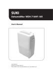
Operating Instructions
Index
Important Hints
Operating instructions transport case
1. Instrument Design
2. Gas Cooler (option)
3. Power Supply
4. Data Memory
5. Instrument Start
6. Input or Selection of combustion plants
7. Flue Gas Analysis
7.1. Gas analysis
7.2. CO measurement (gas path check)
7.3. O2 check
7.4. Draught measurement
7.5. Flow measurement (option)
7.6. Soot dot...Oil trace
7.7. Measurement record and printout
8. Mean Value Measurement (option)
9. Adjustments
10. Control
11. Data Processing
12. Diagnostics
12.1. Fault diagnostic
12.2. delta-T measurement
12.3. Heating check (option)
12.4. 4 Pa measurement (option)
12.5. Pressure Tests (option)
13. Maintenance Tips
14. Technical Data
15. FAQ
Page 2
Page
3
4
7
9
10
10
11
13
16
19
20
20
21
22
23
25
27
31
32
34
36
36
40
41
48
52
53
ecom-D
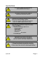
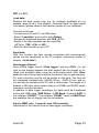
Important Hints
The ecom-D meets the requirements
of the DIN EN 50379 Part 2.
The ecom-D should not be used for
continuous emission control!
Observe the following minimum times in order to
get correct measurement values:
- 1 min. for sensors calibration at fresh air
- 2 min. for stable measurement values
The following substances impair the instrument´s operation:
- Solvent-containing vapours as:
- cleaning agents
- degreasers
- wax polishes
- adhesives
do contain
- Formaldehyde
Adjustments at burners and boilers
should be made only by specialists
who are familiar with these installations.
1. Charge the internal accumulator regularly.
(an unused analyser should be charged at least 1 x per month)!
2. Never store the unit with a discharged battery!
ecom-D
Page 3
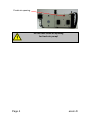
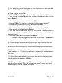
Fresh air opening
Do not lock fresh air opening
for fresh air pump!
Page 4
ecom-D
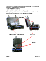
Operating instructions transport case
The ecom-D can be operated in the hard-shell transport case.
Before starting measurements the instrument must be set-up as
follows:
- Pull unlock
- Raise instrument as far as it goes
- Unlocking pin must engage
Unlock
ecom-D
Page 5
The ecom-D is attached with magnets to the holder. To remove the
instrument, please proceed as follows:
- Keep holder with left hand
- Hold eyelet with right hand
- Remove instrument from the holder by pulling
When putting back the instrument in the holder, it must be set with
the two holes on the bottom in the bolts of the holder.
Eyelet
Hard-shell transport
case
Holder
Bolts
Page 6
ecom-D
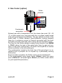
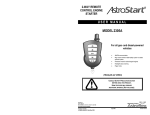
1. Instrument Design
Connection
pressure
Connections for
Pa pressure sensor
Connection
AUX
Connection
USB
Antenna for
Bluetooth or
WiFi
(Option)
Condensation trap
with condensate pad
Connection air
temperature
Slot for multimedia-card
Condensation trap
with gas cooler
and fine dust filter
(Option)
Integral printer
(Option)
Graphic
display
IR diode
(for IR printer)
Connection
draught
Charging LED
Connection gas
temperature
Connection
sampled gas
Connection
charger
ecom-D
Page 7
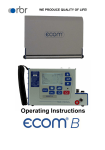
Keyboard
ESC key
(quit/
escape menu)
In the input mode, the keys are
used for numerical inputs
Enter key
(confirm
selection)
Cursor keys
(Up/Down/Right/
Left/Scroll)
Values
recording
Function keys
(function shown on
display)
Page 8
Info key
(access to
control menu)
ON / OFF
key
Print key
(access to
printing menu)
ecom-D
2. Gas Cooler (option)
Peltier
element
WARM
COLD
Condensate
evacuation
Fan
Exhaust gas with a temperature over the steam dew point (35 - 65
°C) is flown spiral via a long gas path thru a surface coated metal
body with good thermal conductivity. The gas radiates its heat to this
metal body. A Peltier element (semi-conductor cooling element)
flown by a continuous current is thermal connected with this body
and with a second metal body with cooling ribs and ventilation slots.
The flow thru the Peltier element creates a heat transfer from WARM
to COLD, drains the heat of the metal body flown by gas and conveys it to the outer cooling body. This heat is conveyed thru a vertical
forced ventilation to the surrounding air.
The condensation issued by the heat loss of the gas drops in a receptacle and is pumped out on request by a periodically working
hose pump.
By accumulator operation, the Peltier cooler can be switched off.
In the measurement menu press hereto <Enter>, select the menu
point „Peltier I/0“ and press again <Enter> (for Peltier cooler switch
on, just repeat this procedure).
ecom-D
Page 9
3. Power Supply
Used accumulators can either be returned
to us or brought to recycling stations of
public waste disposal companies
respectively to stores selling accumulators!
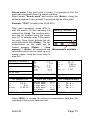
The ecom-D comes with an external charger. The analyser can also
be powered via the internal accumulator for a while (6 V; 3.8 Ah).
The accumulator recharge should be started when the instrument
requires to (acoustical warning and display indication). The accumulator charging stand can be checked looking at the voltage indication
on the display (menu "Control" - Info key). The battery warning is
activated when the value „Accu“ is smaller than 5.9 V.
By 5.8 V the power operation via battery is no more possible; the
instrument must be further powered via the external charger.
4. Data Memory
The multi-media card enables the storage of punctual measurements; the gathered values are written in a text file (J2KDV.txt). Data
format information is to be found in the appendix. The files can be
transferred to a PC via a card reader.
The following conditions must be fulfilled for using a multi-media
card:
- min. card volume 32 MB - max.32 GB (UHC)
- card formatted on 16 bit FAT or FAT32
- SD cards from SanDisk recommended
- PC with card reader
Page 10
ecom-D
Card insert
Insert the multi-media-card as shown.
Take care that the card does not stand
out and that it well hooks on.
Never pull out cards during data record
- data loss and damaging of the
multi-media-card are possible!
5. Instrument Start
Always position the probe in the exhaust pipe once
the calibration phase is over!
Always use a filtering system as per our recommendation for combustion plants
firing solid combustibles!
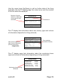
Once the instrument is switched on (key
<I/0>), the main menu is displayed.
6 sub-menus with the following functions (non-visible sub-menus can be
called up while scrolling with the cursor
keys) are displayed:
- Gas analysis
- Soot...Oil trace
- Data processing
- Adjustments
- Control
- Diagnostics
ecom-D
Gas analysis
Soot..Oil trace
Data processing
Adjustments
Control
Diagnostics
: Perform gas analysis
: Input of soot measurement results
: Assign measurements / Data transfer
(only with inserted multi-media-card)
: Modify instrument settings
: Check operation state of instrument
: Read-out of firing automate
(only in connection with ecom-AK) /
delta-T measurement / Heating check /
4 Pa test
Page 11
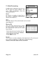
To perform measurements, select with
the cursor keys the sub-menu "Gas
analysis" and confirm with <Enter>.
The instrument starts a 1- minute calibration phase and it enquires if you wish
to use the data bank. If you want to
assign the sampled data to a specific
plant, so press <F1> (<F4> = no:
measurement will be performed without
assignment).
st
Fuel types acc. to 1 BImSchV
Fuel oil (B)
Natural gas (B)
City gas (B)
Coke oven gas (B)
Liquid gas (B)
Use the cursor keys to select the desired fuel type and confirm with <Enter>.
Page 12
Do you wish to
use the data
processing?
Auswählen: <↵
↵> !
JA
NEIN
Fuel type
Fuel oil (B)
CO2max A1
B
15.4
0.50 0.007
Select:
↑↓ ↵
ecom-D
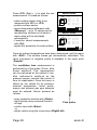
6. Input or selection of combustion plants
To call up plant data already recorded or to create a new file, the
following possibilities are available:
Selection upon:
Create new (is automatically selected
Search word
by first use of a MM card): To create a
new file, a numerical number should be Memory number
Create new
assigned.
Select „Create new“ and confirm with
<Enter>. Input a random number (max. Quit with: ESC
16 figures) using the keyboard:
- use the cursor keys <Up/Down/Right/Left> to select
the figure (selected figure outlined by a black background)
- press <Enter> to accept the figure (press <F2> to delete
the last figure if needed)
- repeat this procedure until the desired number is complete.
Example: "25.09.2014"
Tip: We suggest a date-related input to easily find the data
record later on via the search function.
After confirming with <F1> it is possible to enter a text via the keyboard (max. 6 lines with 20 characters each) which is printed out and
can be used for data processing purposes. Proceed as follows:
- select text line 1 using the cursor keys <Up/Down> and
confirm with <Enter>
- select with <F3> the keyboard mode (4 keyboard modes
are available)
- select with the cursor keys <Up/Down/Right/Left> the desired
character (selected character outlined by a black background)
- press <Enter> to accept the character (press <F2> to delete the
last character)
- repeat this procedure until the desired text is complete.
ecom-D
Page 13
- proceed as follows to correct a character:
- press <F4> to interrupt the character selection
- use the cursor keys <Right/Left> to select the
character requiring correction
- activate with <F4> the character selection and correct character
- return with <F1> to character selection and call up next line for
process
The input is closed with <ESC> and the next available data record is
activated. Press <ESC> to return to the gas analysis menu.
Memory number: For check of the
plant already stored in the instrument,
the selection upon record number is
most appropriate.
Selection upon:
Search word
Memory number
Create new
Select „Memory number“ and confirm
with <Enter>. Input a random data record number:
Quit with: ESC
Example: "3" for data record number 3
Input number
3
Please use the
numerical keys!
- Press <Enter> once the input is completed to call up said data
record number. The cursor keys <Up/Down> enable the check of
the record numbers.
- Press <F1> to select the first record number and <F2> for the last.
- Press <F4> to delete the content of the selected record number.
- Press <Enter> to activate the record number.
- Finally press <ESC> to start the gas analysis.
Page 14
ecom-D
Search word: If the plant code is known, it is possible to find the
plant data stored with help of a search machine.
Select hereto "Search word" and confirm with <Enter>. Using the
software keyboard, input at least 3 connected figures of the plant:
Example: "25.09" for plant code 25.09.2014
After input completion, press <F1> to
start the search. All files matching this
code will be filtered. The resulting selection can be scrolled using the cursor
keys (F1 for selection start, F2 for selection end). Once found, activate the desired data record with <Enter>. The last
measurement on this plant can be
viewed pressing <Enter> / „View
memory“ / <Enter>. All measured and
calculated values can be called up on 5
display pages, using the cursor keys to
step thru.
Memory number 1
O2
CO2
CO
Eff.
Losses
Exc. air
T.Gas
T.Air
3.2
13.1
0
92.5
7.5
1.18
184
20
Memory number 1
25.09.2014
Measurement available
%
%
ppm
%
%
°C
°C
17.5
738
123
7.00
O2
CO 0%
CO
Exc. air
%
ppm
ppm
25.09.2014
12:15 25.09.14
O2 value in air
O2
CO
Draught
O2 value in air
Memory number 1
19.5 %
3 ppm
0.01 hPa
12:15 25.09.14
Gas analysis
Memory number 1
12:15 25.09.14
Soot..Oil trace
Boiler temp.
1.Soot meas.
2.Soot meas.
3.Soot meas.
Oil trace
Soot..Oil trace
Memory number 1
:
:
:
:
:
65°C
0.5
0.3
0.7
NEIN
12:15 25.09.14
CO measurement
Memory number 1
12:15 25.09.14
dT-measurement
T1
T2
dT
70.4
56.3
14.1
dT-measurement
Memory number 1
°C
°C
°C
12:15 25.09.14
Press <ESC> to escape the previous measurement data and the
recording of the current data can start.
ecom-D
Page 15
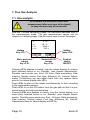
7. Flue Gas Analysis
7.1. Gas analysis
Re-calibrate the instrument after each
measurement (after one hour at the latest)
to keep the accuracy of the results!
After the 1-minute calibration phase, the instrument switches over to
the measurement mode. The gas measurement values can be
viewed on 4 display pages. Use the cursor keys to scroll the pages.
O2
CO2
T.Gas
T.Air
Hotkey
Key <F1>
3.2
13.1
184
20
%
%
°C
°C
BImSchV
Store and print
values
key <F2>
Switch-off CO
sensor
key <F3>
Hotkey
Taste <F4>
Symbol
cooler
ON/OFF
Pressing <F1> enables to switch, from the values display, to a menu
point selected before or on „Standby“ (see chapter Adjustments).
Possible menu points are: Soot...Oil trace, Data processing, View
memory, Display values, Fuel type, Efficiency (K), Internal, Adjustments. Furthermore you can switch back from any random menu
point to the values display with <F1>.
Press <F2> to print out the values simultaneously to their recording
in the intermediate memory.
Press <F3> to cut the CO sensor from the gas path so that it is protected against too high concentrations.
Pressing <F4> also enables to switch, from the values display, to a
menu point selected before or on „Standby“ (see chapter Adjustments). Possible menu points are: Soot...Oil trace, Data processing,
View memory, Display values, Fuel type, Efficiency (K), Internal,
Adjustments (back to values display with <F1>).
Page 16
ecom-D
The position of the measured and calculated values (gas analysis
sub-menu) on the display pages is free selectable. For alteration of
the existing succession, proceed as follows:
- Press <Enter> / „Display values“ / <Enter> to activate the
function
- select line with cursor keys (Up/Down)
- select desired parameter with cursor keys (Right/Left)
- repeat procedure until desired layout is completed
- Press <Enter> to deactivate the function
O2
CO2
CO
Eff.
Losses
Exc. air
T.Gas
T.Air
3.2
13.1
0
92.5
7.5
1.18
184
20
%
%
ppm
%
%
°C
°C
BImSchV
Core stream search
Connect the sampling tubing on the instrument to the plug „Connection gas“. Position the sampling probe in the exhaust channel, so that
the thermocouple is fully surrounded with the gas (see drawing).
Gas stream
Probe tip
Protection bow
Perform the measurement in the core stream of the exhaust gas
channel (probe placed in the hottest gas temperature area). A trend
indication for T.Gas easies the core stream search. As long as the
display shows an arrow in upwards direction, the measured temperature increases, it means the probe tip moves towards the core
stream center. If an arrow in downwards direction is displayed, it
means you move the probe away from the core stream and the temperature sinks. If no temperature change is shown for at least 3 seconds, so the trend indication will disappear.
ecom-D
Page 17
CO2, efficiency, losses, excess air and dew point are calculated values. They can only be calculated if realistic values for the basic parameters like O2 and the temperatures are available. It must be ascertained that:
O2 < 20,5 % and T.Gas - T.Air > + 5 °C
are given. The dew point can only be calculated accurately if, in the
menu "Adjustments", the current barometric air pressure value has
been entered. If the gas temperature falls below the dew point (between 25 and 65 °C), so efficiency will be calculated with condensation gain. In this case a (K) is displayed after „Efficiency“.
Correct measurement values are displayed first after a short delay,
necessary for the gas transport and the build-up of a stable electrochemical reaction to the sensors. This time period lasts approx. 1 to
1.5 minute. For recording, printout and evaluation, wait until the values do not change anymore. If deviations higher than 2 ppm still
occur by the gas values, they can be due to unstable pressure conditions in the exhaust channel.
If the measurement values are stable
and the results can be printed out, press
the key <Record> (disk symbol) to
transfer the values in the intermediate
memory (caution: store separately gas
analysis, CO, O2 check and draught
measurements). They will be kept there
for a later printout and, if need be, for a
final data record storage.
O2
CO2
CO
Eff.
Losses
Exc. air
T.Gas
T.Air
3.2
13.1
0
92.5
7.5
1.18
184
20
%
%
ppm
%
%
°C
°C
BImSchV
Measurement stored in
intermediate memory
If a printout of the values should be made simultaneously to the intermediate recording, so press <F2> (the complete content of the
intermediate memory will be printed).
Page 18
ecom-D
The CO sensor is protected against overload thanks to an internal
programme. If the 4000 ppm limit value is exceeded, so a purging
pump is activated which provides the sensor with fresh air. After
sufficient purging time (X behinds CO disappears) the sensor can be
reintegrated into the measurement system with <F3> (if you choose
„Yes“ at „Adjustments“ / „Internal“ / „CO-Automatic“ the CO
sensor switches to measurement automatically). The sensor can
also be manually be excluded from the measurement system with
<F3>.
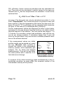
7.2. CO Measurement (gas path check)
The gas channel check, called also CO measurement, is used for the
technical check of gas-fired plants in regards of safety aspects.
Hereby the CO concentration in the gas channel is measured after
the flow safety device and calculated on an undiluted value (oxygen
rest content in flue gas = 0%). As the gas conditions after the flow
safety device are no more homogeneous because of the flow in of
secondary air and consequently the core stream measurement can
be erratic, the analysis of the exhaust gas is performed along the
totality of the exhaust pipe diameter. A multi-hole probe (optional
accessory) is hereby used as sampling probe.
The calculated value shown on the line
„CO 0 %“ corresponds to the measured
CO concentration supposed the oxygen
content would amount 0% by the same
exhaust gas volume. It is consequently
the undiluted CO content in exhaust
gas. If the values indication is stable,
press <Record> to store the result in
the intermediate memory. If a printout of
the values should occur simultaneously
to the recording in the intermediate
memory press <F2> (the complete content of the intermediate memory will be
printed out).
ecom-D
O2
CO 0%
CO
Exc. air
17.5
738
123
7.00
%
ppm
ppm
CO-Messung
Measurement stored in
intermediate memory
Page 19
7.3. O2 check
This measurement is performed by ambient air independent plants
like gross calorific value plants. It is determined if exhaust gas flows
into the combustion air (O2 content drops down / CO content can be
present) and herewith influence on the combustion quality.
For this analysis, a special multi-hole
probe (optional accessory) should be
O2 value in air
used. If the value indicated is stable,
O2
19.5 %
press <Record> to store the value in
CO
3 ppm
the intermediate memory. If a printout of
Draught
0.01 hPa
the values should occur simultaneously
to the recording in the intermediate O2 val. in air
memory, press <F2> (the complete
content of the intermediate memory will
be printed out).
Measurement stored in
intermediate memory
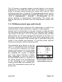
7.4. Draught Measurement
A trend indication for the draught conditions in the exhaust channel
can already be viewed during the gas analysis. Nevertheless the
value for the chimney draught will not be stored together with the gas
values while pressing <Record> because the differential pressure
sensor tends to drifts because of its sensibility.
For an exact measurement, it is consequently advised to re-calibrate
this sensor just before sampling and documenting the value.
The display shows the current value as
well as the recommendation to re-set
the zero point of the sensor. Disconnect
the draught hose from the instrument for
a short moment and press <F4>. The
sensor is herewith re-calibrated.
Page 20
Pressure
Draught
-0.12
hPa
Recorded value:
--.-- hPa
ecom-D
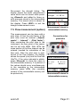
Re-connect the draught tubing. The
display shows the exact measurement
value which can be stored while pressing <Record> and added to those results previous stored in the intermediate
memory. The stored value is shown on
the display. Press <ESC> to exit the
draught measurement menu.
7.5. Flow measurement (option)
This measurement can be done with a
pitot tube. At first the pitot factor of the
pitot tube must be entered („Adjustments“ / „Internal“ / „Pitot factor“).
After connecting the pitot tube to the
instrument, the zero point of the sensor
can be set with <F4>. With <F1> the
cross section of the flow channel can be
entered (needed for calculation of the
flow rate). After the pitot tube is positioned in the flow channel, the display
shows the speed (m/s) and the flow rate
3
(Nm /h). If the value indicated is stable,
press <Record> to store the value in
the intermediate memory. If a printout of
the values should occur simultaneously
to the recording in the intermediate
memory, press <F2> (the complete
content of the intermediate memory will
be printed out).
ecom-D
Pressure
Draught
-0.12
hPa
Recorded value:
-0.12 hPa
Measurement stored in
intermediate memory
Connections for
pitot tube
Flow measurement
Gas speed
M.Flow
0.3 m/sek
44 Nm3/h
Measurement stored in
intermediate memory
Page 21
7.6. Soot...Oil trace
The sub-menu "Soot...Oil trace" enables the input of measured results for
boiler temperature, soot dots and oil
trace. Select the desired line on the
display and activate the input with <Enter>. The input for boiler temperature
and soot measurements 1-3 can be
made one after the other with help of
the instrument keyboard. Press <Enter>
to store the value in the data record of
the measurement.
Soot..Oil trace
Boiler temp.
1.Soot meas.
2.Soot meas.
3.Soot meas.
Oil trace
Select
:
↑↓
:
:
:
:
:
66°C
-.-.-.----
↵
The result of the oil trace check will be documented as follows:
Soot..Oil trace
- Place cursor on line "Oil trace"
- Consign the result with <Enter>
("No", "Yes" or "- - - ")
Boiler temp.
1.Soot meas.
2.Soot meas.
3.Soot meas.
Oil trace
Select
:
↑↓
:
:
:
:
:
66°C
1.0
0.5
1.5
NO
↵
Once all inputs have been entered, press <ESC> to exit the menu.
The measurement is now complete.
Let the probe cool down before fixing it back
for transport!
Page 22
ecom-D
7.7. Measurement record and printout
Important: Once the gas analysis is completed, transfer the values recorded in the intermediate memory on the MM card, otherwise they would get lost by switch-off of the instrument!
Press <Print> (printer symbol) to enter
the printing menu. The sampled data
can be checked one more time („View
memory“, <Enter> and scroll with the
cursor keys).
The software keyboard enables the
input or correction of the 6 lines text of
the plant identification. („Input text“,
<Enter>, to write text, see chapter 7).
All data correct? Then press „Memory
-> M“ and <Enter> to transfer them in
the internal memory or on the MM card
("Disk symbol" is shown in black in the
measurement mode). The inputted text
is taken over into the data record only
by transfer on MM card.
Select („Start printout“ and <Enter>)
to print out the data (only instruments
with printer).
Press <ESC> to turn back to the gas
analysis mode.
The
functions
„View
memory“,
„Memory -> M“ and „Input text“ can
also be selected out of the measurement mode with <Enter>.
--ECOM-D-Start printout
View memory
Memory -> M
Input text
Select
↑↓
↵
--ECOM-D-Start printout
View memory
Memory -> M
Input text
Select
:
↑↓
↵
--ECOM-D-Start printout
View memory
Memory -> M
Input text
Select
:
↑↓
↵
--ECOM-D-Start printout
View memory
Memory -> M
Input text
Select
ecom-D
:
:
↑↓
↵
Page 23
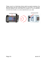
Please care for a frictionless (direct sight) connection between the
sending diode and the receiving diode on the printer. The maximal
distance between both units should not exceed ca. 40 cm otherwise
a trouble free transfer is no more ascertained in any case.
sending diode
Page 24
receiving diode
ecom-D
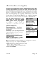
8. Mean Value Measurement (option)
By mean value measurement function, measurements can be sampled within an adjustable time frame and mean values can be calculated. Should the several measurement values or the mean value
result be stored a storage place has to be selected as described in
chapter 7. If the function “Store” is activated, based on this storage
place all measurements will be written consecutively on the next
storage places. If the function “Store” is not activated, the mean
value result can be stored on MMC with <Print> / „Memory -> M.
Once the fresh air calibration is completed, select the menu point „Mean
values“. Before starting, the parameters
„Measurement time“, „Scanning“, „Printer“ and „Record“ should
be checked or modified if need be. The
meaning is respectively:
- Measurement time = Time frame
during which the mean values will
be sampled
- Scanning = Time interval between the
measurements considered for mean
value calculation
- Printer = Documentation of
measurements serving to the mean
value calculation
- Store = All measurements for mean
value calculation will be stored
Gas analysis
Mean value
Soot..Oil trace
Data processing
Adjustments
Control
Diagnostics
Mean values
Start measurement
Measurement time
Scanning
Printer
Store
Select
:
↑↓
↵
„Measurement time“ and „Scanning“ can be adjusted as follows:
- select menu point and confirm with <Enter>
- set the desired time using the numerical keys:
0.01 = 1 sec = minimal value
59.59 = 59 min : 59 sec = maximal value
- confirm with <Enter>
ecom-D
Page 25
The settings for „Printer“ can be changed as follows:
- select menu point and confirm with <Enter>
- select desired adjustment with cursor keys
- confirm with <Enter>
The setting for „Store“ can be changed as follows:
- select menu point and confirm with <Enter>
- activate memory function with <F1> or
- deactivate it with <F4>
By ‘Start measurement’ / <Enter> the
evaluation of the measurement values
will be started. On the display the actual
mean values will be shown (will be updated with new measurement values /
switch to the actual values with cursor
keys <up/down>). It is possible to scroll
through the values with the cursor keys
<right/left>. With <F2> you can interrupt and with <F4> stop the measurement.
O2
CO2
CO
Eff.
Losses
Exc. air
T.Gas
T.Air
3.2 %
13.1 %
0 ppm
92.5 %
7.5 %
1.18
184 °C
20 °C
Mean value
15:35min
After finishing the measurement time a protocol of the results with all
mean values can be printed (only instruments with printer - key
<Print>).
Page 26
ecom-D
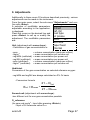
9. Adjustments
Additionally to those ecom-D functions described previously, various
adjustments can be made in the instrument.
From the main menu, select the sub-menu "Adjustments" and confirm with <Enter>.
Adjustments
A selection of modifiable parameters,
adjustable according to the application, Einheit
Ref. O2
is displayed.
Place the cursor on the desired line and Fuel type
press <Enter> to call up or modify the Air pressu
adjustment. The modifiable parameters Select : ↑↓ ↵
are:
Unit (adjustment with cursor keys):
- Calculation of gas concentrations in:
- ppm
3
- mg/m
- mg/kWh (undiluted)
- mg/MJ (undiluted)
- ppm (undiluted)
3
- mg/m (undiluted)
Set clock
Paper feed
Internal
= volume concentration (parts per million)
= mass concentration per volume unit
= mass concentration per power unit
= mass concentration per power unit
= volume concentration (parts per million)
= mass concentration per volume unit
Undiluted:
Conversion of the gas concentration on selected reference oxygen:
- mg/kWh and mg/MJ are always calculated on 0% O2 basis
- Conversion formula
21 – O2ref
Eref = Emeas *
21 – O2meas
Second unit (adjustment with cursor keys):
-two different unit for one gas concentration possible
O2 reference
3
(for ppm und mg/m - Input after pressing <Enter>):
- Input of O2 reference value O2ref
ecom-D
Page 27
Fuel type (press <Enter> to access selection list):
- Modification of adjusted fuel type
(e.g. by measurements at combination-plants)
Air pressure (press <Enter> to access menu):
- Input of barometric air pressure for dew point calculation
Clock set (press <Enter> to access setting menu):
- Correction of internal clock with cursor keys
Paper feed (only instruments with printer)
(press <Enter> to activate paper feeding):
- Paper feed line by line
Internal (press <Enter> to open menu):
- Further instrument settings:
Print contrast
(only instruments with printer)
(press <Enter> to access setting menu):
- Print contrast adjustment with
cursor keys
Display contrast
(press <Enter> to access setting menu):
- Display contrast adjustment with
cursor keys
Key beep
(<F1> for YES / <F4> for NO):
- Acoustical signal by key pressing
Internal
Print contrast
Displ. contrast
Key beep
Language: English
Select:
↑↓
↵
F1 Hotkey
F4 Hotkey
Eff. (C)
CO-Automatic
USB
Bluetooth
WLAN
Pitot-factor
Printout
Language: English (change with <Enter>):
- Info about selected language (3 languages selectable)
F1 Hotkey (selection after pressing <Enter>):
- Modification of adjusted menu the programme will open
after pressing <F1>
Page 28
ecom-D
F4 Hotkey (selection after pressing <Enter>):
- Modification of adjusted menu the programme will open
after pressing <F4>
Efficiency (C) (<F1> for YES / <F4> for NO):
- Efficiency calculation with or without condensation gain
CO-Automatic (<F1> for YES / <F4> for NO):
- Adjustment for CO purging
- YES = CO sensor switches on after purging automatically
- NO (default) = CO sensor has to be switched on with <F3>
after purging
USB (selection after pressing <Enter>):
-Adjustment of transfer speed (Cursor keys <Up/Down>) and protocol (Cursor keys <Right/Left>) for the USB interface (connection
USB):
-Protocol DAS = Protocol for the program DASNT
-Protocol Enhanced = Protocol for the program DAS5
Bluetooth (selection after pressing <Enter>):
- Adjustment of protocol for the Bluetooth interface with the cursor
keys <Right/Left>:
-Protocol DAS = Protocol for the program DASNT
-Protocol Enhanced = Protocol for the program DAS5
With first use of the Bluetooth connection to PC type
in the shown password!
WLAN (selection after pressing <Enter>)
Instrument as Access Point (for connection with mobile terminals):
-(Start/Stop WLAN: manual switching of WLAN connection
– available only with deactivated Auto Connect)
-Access Point: (<F1> for YES / <F4> for NO)
-(W.O.) Auto Connect: Automatic connection
(<F1> for YES / <F4> for NO)
-Channel: Input channel (1 – 13)
(selection after pressing <Enter>)
ecom-D
Page 29
Connection with existing network:
-(Start/Stop WLAN: manual switching of WLAN connection
– available only with deactivated Auto Connect)
-Existing Network: available only with deactivated Access Point
-(W.O.) Auto Connect: Automatic connection
(<F1> for YES / <F4> for NO)
-Network scan: Search for available networks
(selection with <Enter>)
-WPA password: Input of password for selected network
Pitot factor (selection after pressing <Enter>):
- Input of Pitot factor for flow rate calculation (standard = 0.93)
Printout (only instruments with printer)
(selection after pressing <Enter>):
- Text input for printout on measurement protocol (8 x 24 characters)
- Input the text of line 1 as follows:
1. Activate character selection list with <F4>.
2. Select keyboard type with <F3> (4 different keyboards available).
3. Use the cursor keys to select the desired character
(selected character is outlined by black background).
4. Confirm selection while pressing <Enter>.
5. Repeat procedure until desired text is complete.
6. Once input for line 1 is completed, deactivate the characters
selection mode with <F4> and move to the second line with the
cursor key <Down>.
7. Once all lines have been processed as desired, exit the menu
with <ESC>.
Page 30
ecom-D
10. Control
The electrochemical sensors for gas analysis are submitted to a
wearing process and do age. They alter their output values along the
time depending on the gas concentration, the exposure time and the
soiling grade of the sampled gas. The program monitors the sensors
and corrects drifts.
But if the drifts and the correlated measurement errors increase, an
error message is displayed. In this case the corresponding sensor
must be changed by an authorized service center. The control menu
informs about the current status values for the sensors.
Further information is also consigned on 3 display pages (use cursor
keys to scroll):
- battery voltage (charging status);
is displayed as a symbol in all menus:
Full charge
Half charge
Empty
O2 10744 mV
CO
7 mV
Accu 6.09 V
Operation hours
Total
Next unit check
Service tel.
: 8.45 hrs
: 18.75 hrs
: 01.07.15
:02371-945-303
- operation hours since last service
- total operation hours
Further pages: ↑↓
- date of the next recommended service
Program version :V1.2 19.11.14
- phone number of the next service center Serial no.
:D-0001
CO purges
: 15
- software version
Error counter
: 21
- serial number
Operation hours : 8.45 hrs
Total
: 18.75 hrs
- amount of CO switch-offs
Next unit check : 01.07.15
Service tel.
:02371-945-303
- error amount
Further pages:
↑↓
Last service (history)
- Collection of the last maintenance
25.08.11
14.08.12
23.08.13
19.08.14
--.--.---.--.--
88
145
205
322
hrs
hrs
hrs
hrs
Further pages:
ecom-D
↑↓
Page 31
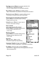
11. Data Processing
If a MM card is inserted in the slot, so it
will be used as record medium. The
menu „Data processing“ offers the
following functions:
Data processing
Select
View
Memory (M)
Format
Quit with:
Select:
For search or creation of plant files in
the scope of assigning measurement
values (see chapter 6.).
ESC
DRT <-> PC !
Datalogger
View:
Recorded values of the selected plant can be viewed
(see chapter 6.).
Memory (M):
Here all stored measurements (sorted
by record number) can be viewed. Single measurement results can be called
up as follows:
- Select desired record number with the
cursor keys and confirm with <Enter>
- Scroll with the cursor keys
- Press <ESC> to exit
Date
1 01.09.14
2 01.09.14
3 01.09.14
4 01.09.14
5 01.09.14
6 01.09.14
7 01.09.14
8 01.09.14
Select
:
11:01
11:02
11:04
11:07
11:11
11:23
11:44
11:53
↑↓
Fuel type
Fuel oil
Fuel oil
Fuel oil
Fuel oil
Fuel oil
Fuel oil
Fuel oil
Fuel oil
↵
Format:
This function is usually needed by initial adjustment of the instrument
at our factory (preparation of MM card for data recording).
Caution: All stored values will be cancelled!
Page 32
ecom-D
DRT <-> PC!:
Load data:
Enables the data import from e.g. rbr software (available on our
website „www.rbr.de“). See chapter „Technical Data“ for data format
information (please observe the transfer options of your software!).
Proceed as follows:
-Connect ecom-D and PC via USB cable.
-Select “Load data“ and confirm with <Enter>.
-Answer the displayed question with YES (<F1>).
-Decide if the data recorded can be cancelled
(<F1> for YES / <F4> for NO).
-Start the data transfer on your PC.
Send data:
With this function the data records completed with measurement
values can be transferred to the PC program (procedure similar to
chapter „Load data“).
Data logger (Option):
Here a Data logger record (“Data logger” and key <OK> / on top
right on the display appears the disk symbol) can be started or finished (just available when using the multi-media-card). With <Record> you can interrupt and continue the record (only in gas analysis).
For each recording one file will be written on the card. The files will
be numbered consecutively (J2KDL-00.csv, J2KDL-01.csv and so
on) and can be transferred to PC with a card reader. The length of a
dataset is 500 byte which means that on a 32 MB card 64000 measurements could be recorded.
In addition to data logger recordings the data could be transferred
online with USB cable (USB Driver / 1200 Baud / Protocol DAS) to
the software “DASNT”. The software “DASNT” and the USB Driver
are available free of charge from the rbr website.
Save to MMC (min. 1 second / max. 999 seconds):
Adjustment of the interval time for data logger recordings.
ecom-D
Page 33
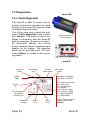
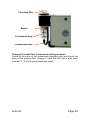
12. Diagnostics
ecom-AK
12.1. Fault diagnostic
The ecom-D is able to receive and to
process information provided via cable
transfer by the ecom-AK (read-out head
for digital firing automates).
Out of the main menu, select the submenu "Fault diagnostic" and confirm
with <Enter>. The ecom-D tries to establish a connection with the ecom-AK
(display message: „Search in process“).
By successful attempt, the current
burner operation stand is displayed as a
graphic on the display. The operation
stand can be recorded (max. 120 sec).
Press <Enter> to initiate a new recording (reset).
Cable connection to
AUX connector
ecom-D
Ignition is
active
Model
name
Flame identified
Current
flame signal
DKO 972 / 22
2.3
Engine
on
OFF
OFF
Oil pre-warmer /
Air pressure
monitor is on
Operation
voltage
Page 34
228
Valve 1
is on
1.2
Min. flame
signal
Recording of operation
stand (max. 120 sec.):
1/0 = Continuous phase
RM = Fan motor
OV = Oil preheater
RZ = Ignition
BV1 = Valve 1st stage
BV2 = Valve 2nd stage
FL = Flame identified
Err = Disturbance
1/0
RM
OV
RZ
BV1
BV2
FL
Err
Valve 2
is on
Reset = Starts a new recording (confirm with
<Enter>)
ecom-D
Use the cursor keys (Up/Down) to call up further data of the firing
nd
automate. On the 2 display page the current error and the number
of burner starts are displayed.
Number of burner
starts at a total resp.
since reset of firing
automate
Current error
No error !
Current error
Number of startups total
Service counter actual
Further pages:
677
142
↑↓
rd
The 3 display lists information about error history (type and volume
of information dependind on firing automat).
Error history
Last 2 errors (Satronic)
Last 5 errors (Siemens)
(Scroll errors using
<Right/Left>)
Flame signal during
straylight check
After:
001
12 sec
Stat :
2.2 µA
225 V
Total
: 46
Straylight
: 22
Safety time
: 9
Loss of flame : 17
FT/LW
: 0
Select:
Error statistics
(number of errors)
↑↓ < >
th
The 4 display page lists information about the monitoring times
(type and volume of information depending on firing automate).
Timing values
Safety time (TSA)
Delay time valve 2
Pre-ignition time
Post-ignition time
Delay straylight sup.
Straylight supervision
Rest time TSA (actual)
Monitoring times of firing
automate
ecom-D
Select:
4.9 sec
40.0 sec
17.0 sec
20.0 sec
11.5 sec
5.0 sec
4.1 sec
↑↓
Page 35
12.2. delta-T Measurement
With the ecom-D a difference temperature measurement is possible.
For measurements at piping (e.g. water-in and water-out of heating
systems), special temperature sensors are needed, available from
your authorized rbr agency. Out of the main menu point "Diagnostics" select the sub-menu "dT measurement" and confirm with
<Enter>.
The instrument indicates the temperadT measurement
ture T1 (sensor at connection „Gas
temperature“), the temperature T2 (senT1
70.4 °C
sor at connection „Air temperature“) and
T2
56.3 °C
the difference between both tempera14.1 °C
dT
tures (T1 - T2). Press <Memory> to
store the result in the intermediate
memory. A printout can be started with
<Print>.
Measurement stored in
intermediate memory
12.3. Heating Check (Option)
The heating check is a simple, expressive process to evaluate a
complete heating plant (heat production, distribution and transfer)
from the energetic point of view.
Hereby the single plant components get inspected by the heating
engineer in a combination of measurements and visual assessment
and valued in regards of their energetic quality acc. to a negative
point system of maximum 100 points.
The higher the score, the farer the current plant is away from the
desirable energetic stand and the higher the energy saving potential
would be if modernization measures are conducted.
In combination with the special probes
required hereto, the ecom-D is able to
perform the measurement of the heating
check parameters: gas losses, ventilation losses and surface losses.
Out of the main menu point "Diagnostics", select the sub-menu "Heating
Check" and confirm with <Enter>.
Page 36
Heating Check
Gas losses
Surface losses
Ventilation losses
Results
Cancel
Select:
↑↓
↵
ecom-D
The gas losses measurement is to be
performed with the instrument´s sampling probe in the gas core stream after
menu call up (see chapter 7.1.). Once
the measurement is recorded with
<Memory> (disk symbol) the conversion of the measurement results in negative points is available under the menu
point „Results“.
O2
CO2
CO
Eff.
Losses
Exc. air
T.Gas
T.Air
3.2
13.1
0
92.5
7.5
1.18
184
20
%
%
ppm
%
%
°C
°C
BImSchV
Measurement stored in
intermediate memory
The surface losses measurement is
performed by a temperature sensor
specific for surfaces. The temperature
difference between boiler surface and
room temperature (air temperature sensor) is determined and the percentage
loss is calculated. Once the menu point
is called up, the boiler performance
must be entered. To easy the measurement width, depth and height of the
boiler can also be entered (dimensions
will be memorized for surface calculation). Please proceed as follows:
- activate respective input window
with <Enter>
- inputs values using the keys numerical
function
- confirm input with <Enter>
or:
- adjust values using the cursor
keys <Right/Left>
Temperature sensor
for surfaces
Surface loss
P.Boiler
Width
Depth
Hight
Modify:
Start
↑↓< >
24.5
1.20
1.20
1.20
kW
m
m
m
↵
Start +
If no boiler dimensions are entered,
press <F1> (Start) to activate the
measurement recording. Here the dimensions for all surfaces must be entered.
ecom-D
Page 37
Press <F3> (Start + ->) to start the real
measurement. Proceed as follows:
- select surface (boiler side) to be
measured with <F1> or <F2>
- position surface sensor
- record temperature difference with
<Memory> - up to 10 values can be
recorded per surface out of which a
mean value will be calculated
automatically
- if need be, cancel measurements
with <F4>
- repeat this procedure for each surface
Surface losses
-0-
Surfa.
Wid.
Hei.
Surf
T.S.
T.A.
T.S.
T.A.
----------21.5
21.5
m
m
m2
°C
°C
°C
°C
Store
Surface losses
-1-
Surfa.
Wid.
Hei.
Surf
T.S.
T.A.
T.S.
T.A.
1.20
1.20
1.44
40.5
21.5
42.5
21.5
m
m
m2
°C
°C
°C
°C
Store
Once all surface temperatures have been determined, quit the menu
with <ESC>. The surface losses get automatically calculated. The
value conversion in negative points is available in the menu point
„Results“.
The ventilation loss measurement is
performed by a flow probe 30 sec. after
burner switch-off. This measurement
can be performed at the earliest 5 min.
after instrument´s switch-on as the
pressure sensor requires this period of
time for stabilization. Once the menu is
called up, the values for air pressure,
external temperature, boiler performance and exhaust gas pipe diameter
must be entered. Hereto proceed as
follows:
- open respective window with <Enter>
- input figures using numerical function
Flow probe
of keys
- confirm input with <Enter>
or:
- adjust values using the cursor keys <Right/Left>
Page 38
ecom-D
Press <F1> (Start) prior to going thru the following steps to start the
measurement:
- release tubing of the flow probe
- wait for zeroing of pressure sensor
- re-connect tubing of the flow probe
- position flow probe into exhaust gas pipe
(observe mark for flow direction)
- switch off burner and simultaneously press <F1>
or:
- press <F2> to activate timer (5 sec.) and switch off burner by beep
- after approx. 30 sec. the measurement value converted in negative
points is available
An overview of the measurements is available under „Results“.
Press <Print> to print them out.
Heating Check
Gas losses √
Surface losses √
Ventilation losses √
Results
Cancel
Select:
ecom-D
↑↓
↵
Heating Check
Gas loss 2.9 %
Points
2.6
Surf. Lo. 2.29 %
Points
3.4
Vent. lo. 3.11 %
Points
3.0
Quit with: ESC
Page 39
12.4. 4 Pa Measurement (option)
The simultaneous operation of room-dependent firing place and air
evacuation system can lead to dangerous low pressure conditions.
With the ecom-D it is possible to check the low pressure limit value
of 4 Pa and to document in a diagram the time course of the low
pressure value. Once the menu point is called up, the measurement
is to be performed as follows:
- connect capillary hose for room where burner is installed to „-“
- connect capillary hose for reference place (staircase or outside
air to „+“
- operate firing and evacuation systems with maximal performance
- open window resp. connection door to burner room and check
the correct evacuation of the exhaust gases
- zero pressure sensor with <F4>
- position capillary hose for reference location
- start record pressure value course with <F1> (Start)
(an acoustical signal is issued every 30 sec. which can be
deactivated / re-activated by pressing <F2>)
- record pressure by opened window resp. connection door
- close window resp. connection door after approx. 30 sec. and
check low pressure
- after approx. 30 sec. open window resp. connection door and
check zero point
- close window resp. connection door after approx. 30 sec. and
check low pressure
- after approx. 30 sec. re-open window or connection door and
check zero point
- after approx. 30 sec. close window resp. connection door and
check low pressure
Once the measurement time is completed, the diagram can be
viewed on the display (use <F3> to emphasize illustration 1x, 2x, 4x,
8x times or A for automatic). Start a printout if needed with <Print>.
Page 40
ecom-D
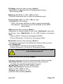
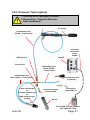
12.5. Pressure Tests (option)
1. Use only air or inert gas for check !
2. Respect the „Technical Rules for
Gas installations“!
Air pump
Connection hose
(Pump – Cross piece)
Electrical
connection
ecomD/UNO
ecom-D
Safety valve
Cross piece
Connection hose
(ecom-D/UNO
- Cross piece)
Connection hose
(Gas system – Cross piece)
Conic test stopple
or
One-pipe counter cap
or
High-pressure test
stopple
Connection ecomD (delta p-)
Connection Squirt
or Soot pump
Connection
ecom-UNO (+)
Squirt
ecom-UNO (only for Loading
and Tightness Test)
ecom-D
Page 41
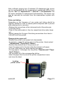
Call up the menu „Pressure Tests“ with the pre-programmed
measurement routines „Pressure Test“, „Loading Test“, „Tightness Test“ and „Usage property“. Parameters to each measurement routine can be adjusted in the menu „Setup“.
Setup
Scroll with cursor keys <Up/Down> until the menu “Setup”. Press
<Enter> to activate the menu. The following parameters can be adjusted for the corresponding measurement routine:
Pressure Test
- Stabilization time (1 - 10 min, default: 1 min)
- Measurement time (10 - 120 min, default: 5 min)
Loading Test
- Stabilization time (1 - 10 min, default: 1 min)
- Measurement time (10 - 120 min, default: 10 min)
- Test pressure (900 - 1200 hPa, default: 1000 hPa)
Tightness Test
- Stabilization time (1 - 10 min, default: 1 min)
- Measurement time (10 - 120 min, default: 10 min)
- Test pressure (90 - 160 hPa, default: 150 hPa)
Usage property
- Stabilization time (1 - 270 min, default: 1 min)
- Measurement time (10 - 240 min, default: 10 min)
- Test pressure (20 - 160 hPa, default: 50 hPa)
- Max. operation pressure (10 - 100 hPa, default: 23 hPa)
- Air pressure (800 - 1200 hPa, default: 1013 hPa)
Each parameter can be adjusted the same way:
1. Select the parameter with cursor keys <Up/Down>.
2. Press <Enter> to activate.
3. Type in the value with the instrument keyboard.
4. Confirm with <Enter>.
Page 42
ecom-D
Pressure Test
The “Pressure Test” up to 100 hPa is deposited as a measurement
routine in the ecom-D. Proceed as follows:
1. Close the conduit with a suitable adapter (test stopple, highpressure stopple or one-pipe counter cap).
2. Connect the components as described before.
3. Scroll with cursor keys <Up/Down> to the menu “Pressure Test”.
Activate with <Enter>.
4. Create the pre-adjusted test pressure (max. 100 hPa) with the air
pump.
5. Interrupt the connection to the air pump (switch-off the ball valve)
and start “Pressure Test” with <Enter>.
6. Wait for stabilization time (the measurement will start automatically).
7. Once the measurement time is over, the result is displayed and
can be printed by pressing <Print>.
8. If the menu “Pressure Test” is selected again, so the result can
be called up with <F4> (as long as the ecom-D is on) or a new
measurement can be started with <F1>.
ecom-D
Page 43
Loading Test
The „Loading Test“ acc. to DVGW – TRGI Process Instructions G
600 by pipes (operation pressure up to 100 hPa) is deposited as a
measurement routine in the ecom-D. Proceed as follows:
1. Connect the ecom-UNO to the connection AUX of the ecom-D.
2. Close the conduit with a suitable adapter (test stopple, highpressure stopple or one-pipe counter cap).
3. Connect the components as described before.
4. Scroll with cursor keys <Up/Down> to the menu „Loading Test“.
Activate with <Enter>.
5. Create the pre-adjusted test pressure with the air pump (the unit
beeps as soon as the pressure level is achieved).
6. Interrupt the connection to the air pump (switch-off the ball valve).
7. Wait for stabilization time (if the pressure remains in the range
„test pressure +/- 10% during stabilization time, so the measurement
will start).
8. Once the measurement time is over, the result is displayed and
can be printed by pressing <Print>.
9. If the menu „Loading Test“ is selected again, so the result can
be called up with <F4> (as long as the ecom-D is on) or a new
measurement can be started with <F1>.
Page 44
ecom-D
Tightness Test
The „Tightness Test“ acc. to DVGW – TRGI Process Instructions G
600 by pipes (operation pressure up to 100 hPa) is deposited as a
measurement routine in the ecom-D. Proceed as follows:
1. Connect the ecom-UNO to the connection AUX of the ecom-D.
2. Close the conduit with a suitable adapter (test stopple, highpressure stopple or one-pipe counter cap).
3. Connect the components as described before.
4. Scroll with cursor keys <Up/Down> to the menu „Tightness
Test“. Activate with <Enter>.
5. Create the pre-adjusted test pressure with the air pump (the unit
beeps as soon as the pressure level is achieved).
6. Interrupt the connection to the air pump (switch-off the ball valve).
7. Wait for stabilization time (if the pressure remains in the range
„test pressure +/- 10% during stabilization time, so the measurement
will start).
8. Once the measurement time is over, the result is displayed and
can be printed by pressing <Print>.
9. If the menu „Tightness Test“ is selected again, so the result can
be called up with <F4> (as long as the ecom-D is on) or a new
measurement can be started with <F1>.
ecom-D
Page 45
Usage property
The „Usage property“ acc. to DVGW – TRGI Process form G 624
by conduits is deposited as a measurement routine by the ecom-D.
The calculation of the leak rate happens automatically according to
the following equation and corresponds herewith to the procedure of
the DVGW-TRGI Process Form G 624:
VB = V/TM * ((PA + P1)/(PA + P2)-1) * PB/P1 * f
with: VB = Gas leak volume in operation state (l/h)
V = Pipe content in litres
TM = Measurement duration in hours
PA = Barometer stand in hPa
P1 = Test pressure at meas. beginning in hPa
P2 = Test pressure at measurement end in hPa
PB = Maximal gas operation pressure in hPa
f = Factor for consideration of gas type
Proceed as follows:
1. Close the conduit with a suitable adapter (test stopple, highpressure stopple or one-pipe counter cap).
2. Connect the components as described before.
3. Scroll with cursor keys <Up/Down> to the menu „Usage property“. Activate with <Enter>.
4. Type in the air pressure (PA) with the instrument keyboard and
confirm with <Enter>.
5. Choose the gas type (f) with cursor keys <Up/Down> and confirm
with <Enter>. The following gas types are recorded with their respective factors:
Natural Gas, Air, Town Gas, Propane, Butane, Hydrogen
6. Type in the maximal operation pressure (PB) with the instrument
keyboard and confirm with <Enter>.
Page 46
ecom-D
7. The pipe volume (V) is needed for the calculation of the leak rate.
The ecom-D offers two possibilities:
a. Type in pipe volume (V):
- Choose NO at the inquiry „Calculate Volume automatically?“.
- Type in pipe volume (V) with the instrument keyboard and confirm
with <Enter>.
b. Calculate pipe volume automatically (V):
- Choose YES at the inquiry „Calculate Volume automatically?“
- Connect the squirt or soot pump as described before.
- Open ball valve and wait until the pressure is stabilized.
- Choose squirt or soot pump with the cursor keys <right/left>.
- Start volume calculation with <Enter>.
- Infer the test volume with squirt or soot pump. The decrease of
pressure must be min. 2 hPa (otherwise operate squirt or soot pump
several times).
- Close ball valve and confirm with <Enter>.
- Choose number of strokes with the cursor keys < right/left >
and confirm with <Enter>.
8. Create the pre-adjusted test pressure with the air pump (the unit
beeps as soon as the pressure level is achieved).
9. Interrupt the connection to the air pump (switch-off the ball valve).
10. Wait for stabilization time (if the pressure remains in the range
„test pressure +/- 10% during stabilization time, so the measurement
will start).
11. Once the measurement time is over, the result is displayed and
can be printed by pressing <Print>.
12. If the menu „Usage property“ is selected again, so the result
can be called up with <F4> (as long as the ecom-D is on) or a new
measurement can be started with <F1>.
ecom-D
Page 47
13. Maintenance Tips
Do not use other sensors or feelers from other manufacturers otherwise the TÜV / DIN EN approval will not
be valid anymore!
To secure the accuracy of your measuring instrument we recommend the annual check by an authorized ecom partner. In the case
of strong demand (e.g. permanent several hours of measurement
per day, rough conditions etc.) shorter intervals between checks
should be selected - please contact your ecom partner. All ecom
partners are listed under www.rbr.de.
Service made by service centers non-authorized by
rbr Messtechnik GmbH will result in a complete and
immediate loss of any warranty!
The following advices will be of help for the daily check and maintenance of single parts or assemblies:
Empty condensate trap (Instruments with gas cooler):
The condensate collects the humidity of the sampled gas. Check
regularly how much liquid has been gathered. Empty the trap in time
and avoid humidity to enter the instrument. Remove condensate
hose from nipple and let the condensate out. Note: The condensate
hose must be attached to the nipple during the measurement!
Page 48
ecom-D
Fine dust filter
Nipple
Condensate trap
Condensate hose
Change Fine dust filter (Instruments with gas cooler)
Screw off the cover of the condensate trap/gas cooler and check the
state of the particle filter. Change it once the filter has a grey color
(number 2 - 3 of the soot comparison scale).
ecom-D
Page 49
Condensate pad (Instruments without gas cooler)
Regularly check the condition of the condensate pad. It should be
changed:
- If it is soiled darker than no. 3 on the soot scale
- If its extension is on mark "MAX"
Replace the condensate pad as follows:
1. Remove hose from the cap and unscrew the cap
2. Unscrew the retaining bolt with spring
3. Replace old condensate pad against new
4. Screw on retain bolt with spring again
5. Screw on cap and replace the hose to the cap
Sensors
The sensors get calibrated with the reference gas fresh air by each
switch-on. Their state is permanently checked by the instrument.
New sensors age along the operation time because of the wearing of
the reagents (oxygen sensor) and due to soiling respectively exceeding concentrations beyond the nominal measurement range (toxic
sensors). The output values of the sensors are (menu "Control"):
O2
Others
approx. 20000 mV
0 mV (+/- 150)
If an error message is displayed during calibration and cannot be
eliminated despite several calibration phases, so the instrument must
be checked by a qualified and authorized service center. The oxygen
sensor must show a value of >7000 mV, otherwise it must be
changed by an authorized service center.
The CO sensor is protected against overload by the internal program. If the limit value of 4000 ppm is exceeded, a second pump
switches on and flows the sensor with fresh air.
Page 50
ecom-D
After sufficient purging time (X behinds CO disappears) the sensor
can be reintegrated into the measurement system with <F3> (if you
choose „Yes“ at „Adjustments“ / „Internal“ / „CO-Automatic“ the
CO sensor switches to measurement automatically). The sensor can
also be manually be excluded from the measurement system with
<F3>..
Probe and tubing
Depending on the frequency of use, probe and tubing should be
regularly cleaned in order to release particle deposits and to prevent
early wearing due to corrosion.
-Release the connections at the instrument and at the probe grip
to free the tubing.
-Clean it (flow warm water in then dry respectively blow water drops
out.
-Slightly grease the O-rings of the tubing connections from time to
time with acid-free grease.
Change printer paper roll
-Release the printer cover (press lock downwards).
-If necessary, extract the paper rest out of the printer. Hereto select
"Adjustments"/"Paper feed"/<Enter>).
-Remove the plastics tube of the previous roll.
-Insert the paper end in the slot under the transport roll (paper
roll inner side facing you while inserting the paper).
-Convey approx. 3 cm paper thru the printer ("Adjustments"/"Paper
feed"/<Enter>).
-Lay the paper roll in the corresponding hollow.
-Insert the paper thru the slot of the printer compartment cover
and close the latest.
Locking
printer cover
ecom-D
Page 51
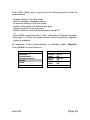
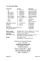
14. Technical Data
Parameter
Range
0 ... 21 vol.%
O2
CO
0 ... 4000 ppm
NO (option)
0 ... 5000 ppm
NO2 (option)
0 ... 1000 ppm
SO2 (option)
0 ... 5000 ppm
H2S (option)
0 ... 1000 ppm
CO% (option)
4000 ... 63000 ppm
CO2 (option)
0 ... 20 vol. %
CO2
0 ... CO2max
T-Gas
0 ... 500 °C
T-Air
0 ... 99 °C
Differential pressure 0 ... +/- 100 hPa
Efficiency
0 ... 120 %
Losses
0 ... 99,9 %
Excess air
1 ... ∞
CO undiluted (adjustable ref. O2)
Flue gas dew point
Power supply
Protocol printer
Indication
Dim. (W x H x D)
Weight
Principle
Electrochemistry
Electrochemistry
Electrochemistry
Electrochemistry
Electrochemistry
Electrochemistry
Electrochemistry
Infrared
Calculation
NiCr-Ni
Semi-conductor
DMS bridge
Calculation
Calculation
Calculation
Calculated
Calculated
Charger 230 V / 50 Hz~; Battery 6 V / 3,3 Ah
integral; 58 mm paper width (option)
graphic display; backlit
from approx. 200 mm x 130 mm x 80 mm
(depending on selected features)
from approx. 2 kg
(depending on selected features)
Subject to technical changes
V2.1 / 02.2015
rbr Messtechnik GmbH
Am Großen Teich 2
D-58640 Iserlohn
Phone: +49 (0) 2371 - 945-5
Fax: +49 (0) 2371 - 40305
Internet: http://www.rbr.de
eMail: [email protected]
Page 52
ecom-D
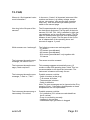
15. FAQ
Where do I find important instrument information?
In the menu „Control“ all important instrument informations are shown (e.g. battery voltage, sensor
values, unit number, next service date, operation
hours etc.). With the arrow keys stands you can
switch to the second page.
How long is the life span of the
sensors?
The life span depends on the operating hours and
the instrument equipment. The life span of the toxic
sensors (CO, NO, SO2, NO2) is affected by high gas
concentrations and a not sufficient purging. The life
span for these sensors amounts to on the average
between 4 and 6 years. The life span of the O2 sensor is independent of the operating hours and
amounts to approx. 2 years.
Which sensors can I exchange?
The following sensors are exchangeable:
- O2 sensor
- CO sensor (precalibrated)
- NO sensor (precalibrated)
- SO2 sensor (precalibrated / only together with
CO sensor
The instrument shows the error
message „O2 sensor 0 mV“!
The sensor must be renewed.
The instrument shows the message „Check required“!
This message appears automatically every 12
months or after 250 operating hours. Note: This is a
recommendation to let check the instrument. The
instrument is however still ready for use.
The instrument shows the error
message „T-Gas“ or „T-Air“!
Possible reasons could be:
- Cable is broken (at the plug)
- T-Air sensor is broken
- Thermocouple is broken
- Cable is defective
Note: The error messages can be ignored at the D by
pressing „Enter“. Calculations that depends on these
temperatures are not implemented.
The instrument shows wrong or
inaccurately CO2 values!
Possible reasons could be:
- O2 is defective (CO2 values are calculated from
the O2 values)
- Pump is not working correctly
- Leakage in the gas way
- condensate trap / gas cooler is clogged
ecom-D
Page 53
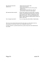
My instrument cannot be
switched on!
- Please check the mains cable
- Please check the fuse
- Please check mains connection (Plug socket
switched on?)
- Please load the accumulator min. 8 hours
(Accumulator could be over-discharged)
My instrument does not print!
Please check whether the printer paper is correctly
inserted. The thermal printer writes only on the thermally sensitive side. Please use always the correct
paper for the printer, you will prevent defects at the
printer. Please make sure that the printer is clean (no
chads in the drive).
Can I change the printout?
You can change the printout (Menu: Adjustments).
Hint: If you have several instruments of the same type, you can locate an error by
exchanging the accessories (probe, hose, temperature sensor etc.).
If further questions or problems should arise, please contact the next authorised service centre.
Page 54
ecom-D
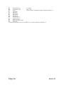
Description of data record ecom-D with Multi Media Card
Format data logger records: J2KDL-xx.csv (separation mark between values = comma)
Format punctual measurements: J2KDV.txt (separation mark between values = comma)
Column
A
B
C
D
E
F
G
H
I
J
K
L
M
N
O
P
Q
R
S
T
U
V
W
X
Y
Z
AA
AB
AC
AD
AE
AF
AG
AH
AI
AJ
AK
AL
AM
AN
AO
AP
AQ
AR
AS
AT
AU
AV
AW
AX
AY
AZ
BA
BB
BC
BD
BE
Description
Date
Time
O2 in vol.%
CO in ppm
NO in ppm
NO2 in ppm
SO2 in ppm
CO converted*
NO converted*
NO2 converted*
NOX converted*
SO2 converted*
T .Gas in °C or °F
T. Air in °C or °F
Draught in hPa
CO2 in vol.%
Efficiency in %
Losses in %
Excess air
Dew point in °C oder °F
Poisoning index
O2 (gas channel check) in vol.%
CO (gas channel check) in ppm
CO (gas channel check) in ppm
O2 (O2 check) in vol.%
T. Boiler
T. Sensor
O2 reference
Unit
Norm
Fuel type number
Fuel type text
Soot 1
Soot 1
Soot 1
Oil trace
20 characters text
20 characters text
16 characters text
Serial number
CO (O2 check) in ppm
Zug (O2 check) in hPa
CxHy
Number copy data
T1 (deltaT-measurement)
T2 (deltaT-measurement)
Velocity
CO Environment
free
Comment text
Comment text
Comment text
Comment text
H2 in ppm
H2 converted*
Sensor 6 in ppm
Sensor 6 converted *
ecom-D
Remark / Example
DD.MM.YYYY (also US-Version)
HH:MM:SS (also US-Version)
0,0 - 21,0
0 - 4000
0 - 5000
0 - 1000
0 - 5000
0 - 500 (US-Version with other range in °F)
0 - 99 (US-Version with other range in °F)
0,00 - 20,00
0,0 - 25,0
0,0 - 120,0
0,0 - 100,0
> 1,00
0 - 500 (US-Version with other range in °F)
> 0,0
0,0 - 21,0
Related to 0,0 vol.% O2
Measured value
0,0 - 21,0
0 - 999
0 - 99
0,0 - 21,0
3
0=ppm; 1=mg/m ; 2=mg/kWh; 3=mg/MJ
N = converted to O2 ref.
Index acc. to instrument table
Text acc. to instrument table
0,0 - 9,9
0,0 - 9,9
0,0 - 9,9
0=no; 1=yes;
m/s
CH-version = Kind of control
CH-version = Load range
CH version = Oil consumption
CH version = Thermal output
CH version = Operation hours counter
CH version = Code
Page 55
BF
dP (velocity) in Pa
0 – 1000,00
BG
Air pressure in hPa
300 – 1100
BH
Unit 2
0=ppm; 1=mg/m3; 2=mg/kWh; 3=mg/MJ; 4=ppmN; 5=mg/m3; 6=--BI
CO (Unit 2)
BJ
NO (Unit 2)
BK
NO2 (Unit 2)
BL
NOx (Unit 2)
BM
SO2 (Unit 2)
BN
Analogue input 1
BO
Analogue input 2
BP
Sensor 7 in ppm
BQ
Meas. gas volume in l/min
BR
last column
0
* converted to unit (column AC) and converted on O2 ref. (Column AB) when column AD = N
Page 56
ecom-D