1
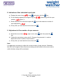
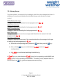
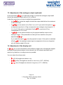
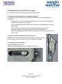
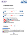
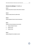
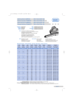
Operating Instructions Evaluation Unit AE12 and Rope Load Sensor LS1 & LS2 1. Dimensions Versorgungsspannung power supply - + Messkanäle 1-12 measuring channels 1-12 Analogausgang analogy output Hold Hold + AL-F AL-E AL-S AL-O Page 2 Copyright 2009 by Henning GmbH Rev. 2.0 2/2009 2. Connection diagram Page 3 Copyright 2009 by Henning GmbH Rev. 2.0 2/2009 3. Description of alarm relays AL-E (Empty load relay) Change of state on falling below the load programmed in . AL-F (Full load relay) Change of state on exceeding the load programmed in . AL-O (Overload relay) Change of state on exceeding the load programmed in . AL-S (Slack rope and rope difference relay) Change of state as soon as the car empty load falls below the value of the load programmed in AND Change of state as soon as one of the ropes deviates from the average of all ropes at least by the load programmed in . Note: The working procedure of the relays as a make or break contact can be changed for each alarm output using the parameter. 4. HOLD function The HOLD input responds for alternating and direct voltages between 12 V to 230 V. During the elevator travel the measured loads can heavily fluctuate (friction in the rails etc.). As long as a voltage (e. g. the travel signal) between 12 to 230 V is applied at the HOLD input the alarm output through the alarm relays does not take place. 5. Access to the parameters The unit is equipped with a menu by which the individual setting parameters can be reached. By pressing this key the individual menu items are cycled through. If one menu item has been selected, the key is used for the navigation of the submenus. Within the individual parameters the value can be changed by this key. Using this key the currently displayed menu item is selected, or in the parameters he set value is adopted. Page 4 Copyright 2009 by Henning GmbH Rev. 2.0 2/2009 Using this key the new selected menu items and parameter settings are cancelled. Repeatedly pressing this key finally leads to the display of the total weight. Note: After one minute without operation the unit automatically returns to the display of the total weight, independent of the menu item that was previously selected. After 10 minutes without operation the unit switches to low consumption mode, i. e. the display switches off and can be reactivated on the next operation. 6. Change of a parameter 1.) Use the key to display the parameter that is to be changed. 2.) Select the parameter using the 3.) Use the key. key to change the value of the currently flashing digit position. Switch to the next position using the 4.) After input of the final digit reuse the 5.) Press the key. key. Now the total value is flashing. key again in order to adopt the value. Page 5 Copyright 2009 by Henning GmbH Rev. 2.0 2/2009 7. Menu structure Weight indication (4 digits in kg) Indication of the individual rope loads (rope) Setting of the number of ropes / rope sensors (rope count) Adjustment of the rope suspension ratio (rope factor) Zero point adjustment (zero) Alarm phase Empty Load (alarm empty) Alarm phase Full Load (alarm full) Alarm phase Overload (overload) Alarm phase Slack Rope (alarm slack rope) Alarm phase Rope Load Difference (alarm rope load) Adjustment of the analogue output (DC out) (only relevant for the AE12 with analogue output) Adjustment of the display weight unit (unit) Version number (Program version) Page 6 Copyright 2009 by Henning GmbH Rev. 2.0 2/2009 8. Indication of the individual rope loads a) Display the menu item using and select with the key. b) On the display appears the weight in kg (e.g. ) alternating with the rope number (rope 1). c) Switch between the individual ropes with (up to the maximum number of ropes adjusted in ). d) At any time you can leave the menu item with . 9. Adjustment of the number of rope sensors a) Select the menu item (rope count) using and then press the key. b) Follow the instructions under point 6 „Change of a parameter“ in order to adjust the correct number of rope sensors. c) At any time you can leave the menu item with . Note: It is absolutely necessary to adjust the correct number of rope sensors. Otherwise the AE12 will recognize that sensors are missing and will switch to the error mode in which all alarm relays will be activated. Page 7 Copyright 2009 by Henning GmbH Rev. 2.0 2/2009 10. Adjustment of the suspension ratio In the case of multi-suspension you have to set the factor by which the rope loads are multiplied. a) Select the menu item (rope factor) with the key and then press the key. b) Follow the instructions under point 6 „Change of a parameter“in order to adjust the correct factor. Example: in the case of a 2 : 1 suspension you have to enter the factor c) At any time you can leave the menu item with . 11. Zero point adjustment With this function the total weight indicated on the AE12 unit is reduced by the empty weight of the car, i. e., in the case of an empty car the display shows 0 kg. a) Select the menu item with the key and then press . Now on the display starts flashing. b) Please check that the car is really unloaded. After pressing the key again a 10 second countdown will start. During this period of time the car weight must not be changed. c) Then the zero point is balanced Note: The function Slack Rope Alarm only functions with a balanced empty load of the car. Therefore, it is absolutely necessary that you make this zero point adjustment when using the slack rope alarm. Page 8 Copyright 2009 by Henning GmbH Rev. 2.0 2/2009 12. Alarm phases The alarm phases correspond to the loading at which the relays change their state. In addition you may choose whether the individual relays work as make or break contact. AL-E (Empty load relay) Change of state on falling below the load programmed in . AL-F (Full load relay) Change of state on exceeding the load programmed in . AL-O (Overload relay) Change of state on exceeding the load programmed in . AL-S (Slack rope) Change of state as soon as the car empty load falls below the value of the load programmed in . AL-r (Rope difference) Change of state as soon as one of the ropes deviates from the average of all ropes at least by the load programmed in . a) Select the corresponding alarm phase with b) Now, with the (configuration). and then press the key. key you select between (load) and c) In you set the load switching threshold in kg. In you can select between (close) for the operating mode MAKE and (open) for the operating mode BREAK. The setting is only adopted after the second use of the key (selection flashes after the first use) Page 9 Copyright 2009 by Henning GmbH Rev. 2.0 2/2009 13. Adjustment of the analogue output (optional) At the parameter you adjust the weight, at which the analogue output shall deliver the maximum output value of 10V or 20mA. Under this menu item you have to adjust three parameters: - At you select the weight at which the output shall deliver the maximum of 10 V or 20 mA. - In you can switch a “live Zero” on or off. If you switch this option to a measured rope load of 0 kg corresponds to an analogue output signal of 2 V or 4 mA. If the option is switched off with a rope load of 0 kg corresponds to 0 V or 0 mA. - In you can select whether only the payload shall be output via the analogue output. (The precondition is that you have used the zero point adjustment If you select the option , only the payload is output. If the option is switched off with the analogue output signal corresponds to the sum of payload plus the empty weight of the car. 14. Adjustment of the display unit At you can choose between three different weight units. All displayed weights and alarm thresholds are shown in the selected unit. All internal calculations are made in kg, therefore, rounding errors are possible. You can select from these units: - (SI) All weights are shown in kg. (tnSh) All weights are shown in short tons (1 S/T = 2000 lb). (tnL) All weights are shown in long tons (1 L/T = 2240 lb). Page 10 Copyright 2009 by Henning GmbH Rev. 2.0 2/2009 15. Electrical Values Power supply voltage 12 V – 28 V DC Power consumption max. 4 W (all Relays activated) Fuse 1 A mT HOLD input 12 V - 230 V AC/DC Relay outputs max. Switching voltage 250 V AC max. Starting current 15 A max. Continuous current 10 A max. Switching capacity 2500 W (resistive load) max. Switching capacity (inductive 500 VA load) min. Switching load DC 0.3 W Analogue output (optional) galvanically isolated yes Voltage output 2 V – 10 V or (resistive load > 500 Ω) 0 V – 10 V Current output 4 mA – 20 mA or (resistive load < 500 Ω) 0 mA – 20 mA 16. Change of a fuse a) b) c) d) Disconnect the AE12 from the power supply voltage. Remove the base plate from the unit rear side. Remove the circuit board from the housing. Change the fuse 1mA mT. You will find the fuse switch directly behind the terminals of the power supply voltage. Page 11 Copyright 2009 by Henning GmbH Rev. 2.0 2/2009 17. Error messages All 4 alarm LED's light up At least one load sensor has failed or the wrong number of sensors has been set under menu item . Action: Select menu item and verify the number of sensors set. If this number has been set correctly and the error still exists, go to menu item and verify the individual ropes. If is indicated, the relevant sensor has failed. If is indicated, the relevant sensor supplies too high a signal and is overloaded. Page 12 Copyright 2009 by Henning GmbH Rev. 2.0 2/2009 18. Installation of the LS1 & LS2 sensors For each carrying rope one load sensor must be provided. 1.) Selection of the appropriate installation position The point on the rope where the load sensor is installed must fulfil the following conditions: - -During travel over the total lifting height the sensor must not make physical contact with any other components. - -At the installation position selected the rope must run straight and be entirely undamaged. - At the selected point there must not have been previous mechanical influences such as other rope sensors, multiple installations etc. - -Between the cable joint and the load sensor there must be a minimum 10 cm of free rope. 2.) Insertion of the load sensor LS into the rope Open the rope clamp with the M5 screw enough to allow the rope to lie in the groove of the load sensor over the total sensor length. 3.) Closing of the rope clamp Tighten the M5 screw to 4 Nm (verification: both lock washers are flattened, see photo). Page 13 Copyright 2009 by Henning GmbH Rev. 2.0 2/2009 4.) Connecting the sensor to the evaluation unit AE12 The load sensors LS1 must be connected to the AE12 starting with sensor socket 1 in the upper left corner of the housing: 1 2 3 4 5 6 7 8 9 10 11 12 - + Repeat steps 1 to 4 for all sensors to be connected. Note: For an exact measurement result the sensor must only be clamped once onto the selected point of the rope. Page 14 Copyright 2009 by Henning GmbH Rev. 2.0 2/2009 19. Short operating instructions 1.) Install the evaluation unit AE12 in an appropriate location. 2.) Installation of the sensors (see point 18). 3.) Adjustment of the number of sensors (see point 9). With switch to menu item and adjust the number with and . Press twice to confirm the adjustment. 4.) Adjustment of the suspension factor, only necessary if it is not a 1:1 suspension (see point 10). With switch to menu item and adjust the number with and . Press twice to confirm the adjustment. 5.) Adjustment of the alarm thresholds (see point 12). With and choose the corresponding alarm phase. In adjust with and the load switching threshold. In adjust the operating mode for make contact and for break contact. Press twice to confirm the adjustment. 6.) Carry out zero balancing of the unit with empty elevator (see point 11). With switch to menu item . Press twice and the countdown will start. Note: It also is possible to carry out all parameter settings of steps 3.) 4.) and 5.) and the computer-aided rope adjustment in comfort with our free of charge WeightWatcher Software using the USB interface of the AE12. You will find this software on our home page www.henning-gmbh.de at Software. Page 15 Copyright 2009 by Henning GmbH Rev. 2.0 2/2009 Henning GmbH Industriegebiet S5 Loher Str. 4+30 58332 Schwelm (Germany) Tel.: +49 2336 9298-0 Fax.: +49 2336 9298-10 [email protected] www.henning-gmbh.de Page 16 Copyright 2009 by Henning GmbH Rev. 2.0 2/2009