1
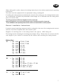
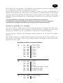
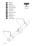
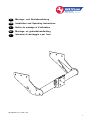
D GB Montage- und Betriebsanleitung Installation and Operating Instructions F Notice de montage et dutilisation NL Montage- en gebruikshandleiding I Istruzioni di montaggio e per luso 307 284 691 101 - 10/05 - 001 1 D Montage- und Betriebsanleitung Anhängebock Westfalia-Bestell-Nr.: Typ: EG-Genehmigungszeichen nach Richtlinie 94/20/EG: 307 284 307 279 Verwendungsbereich: Van-Kasten, PKW-Kombi, Kombi-Van, PKW-Kleinbus, Fg. Einzelkabine, Fg. Doppelkabine, Nugget, LKW-Kombi e13 00-1013 Amtliche Typenbezeichnung nach EG-Typgenehmigung: EAS, EDS, ESS, EBS, EMS, ENS, EUS, EAL, EDL, EGL, ECL, ESL, ESG, EBL Hinweis: Kugelplatte und Distanzstück, welche nicht besonders gekennzeichnet sind, gehören mit zu dem Genehmigungsumfang von Anhängebock und sind mit der bildlichen Darstellung der Montage- und Betriebsanleitung zu vergleichen. Auch die Bolzenkupplung incl. Wechselplatte sind im Genehmigungsumfang enthalten. Technische Daten: Der geprüfte D-Wert beträgt 14,47 kN. Dieser entspricht zum Beispiel einer Anhängelast von 2550 kg und einem zulässigen Gesamtgewicht von 3500 kg. Die geprüfte Stützlast beträgt 100 kg. Für den Fahrbetrieb sind die Angaben des Fahrzeugherstellers bzgl. Anhängelast und Stützlast maßgebend, wobei die geprüften Werte der KmH nicht überschritten werden dürfen. Hinweise: Der Anhängebock ist serienmäßig mit der Kugelplatte und Distanzstück, wie in der Abbildung gezeigt, versehen ( Kugelposition A,B,C) Es darf jedoch auch ersatzweise eine selbsttätige Bolzenkupplung montiert werden. Kugelplatte und selbsttätige Bolzenkupplung darf auch in Verbindung mit einem Kupplungsschnell-wechselsystem (Bes-t.-Nr.342 032 600 001) kombiniert werden. (ohne Distanzstück ). -ALKO / MFK Typ 1500 Bei Einsatz des Schnellwechselsystems Kugelplatte Best.-Nr.: 329 053 , 329 049 oder 321 168 Der Anhängebock ist ein Sicherheitsteil und darf nur von Fachpersonal montiert werden. Sofern Ersatzteile erforderlich werden, dürfen auch diese nur von Fachpersonal am unbeschädigten Originalteil verbaut werden. Jegliche Änderungen bzw. Umbauten an dem Anhängebock sind unzulässig. Die Kugel bzw. Kupplung ist sauber zu halten und zu fetten. Der Durchmesser der Kugel ist von Zeit zu Zeit zu überprüfen. Sobald an einer beliebigen Stelle eine Verschleißgrenze von 49,0 mm erreicht ist, darf die KmH aus Sicherheitsgründen nicht mehr benutzt werden. 2 D Bei Fahrt mit Anhänger sind die Fahrthinweise in der Betriebsanleitung des Fahrzeugherstellers zu beachten. Die Anhänger müssen mit einer entsprechenden Zugkugelkupplung ausgerüstet sein. Muß durch den Anbau des Anhängebockes die Abschleppöse entfernt werden, dient der Anhängebock als Ersatz hierfür, sofern die zulässige Anhängelast nicht überschritten wird und der Abschleppvorgang auf verkehrsüblichen Straßen erfolgt. Die vom Fahrzeughersteller serienmäßig genehmigten Befestigungspunkte sind eingehalten. Nationale Richtlinien über die Anbauabnahmen sind zu beachten. Diese Montage- und Betriebsanleitung ist den Kfz. - Papieren beizufügen. Allgemeine Montagehinweise : Isoliermasse bzw. Unterbodenschutz am Kfz. - falls vorhanden - im Bereich der Anlagefläche des Anhängebockes entfernen. Blanke Karosseriestellen mit Rostschutzfarbe bestreichen. Sämtliche Befestigungsschrauben des Anhängebockes nach ca. 1000 Anhänger-km nachziehen. Dieser Anhängebock einschließlich aller Montageteile wiegt 18 kg. Bitte berücksichtigen Sie, daß sich das Leergewicht Ihres Kfz. nach Montage des Anhängebockes um diesen Betrag erhöht. Kugelposition: "A" = Typ: EAS FT 80 , FT 100 Typ: Typ: Typ: Typ: Typ: Typ: EDS ESS EBS EUS EAL EDL FT 80 , FT 100 FT 100 FT 8 / 9 FT 100 FT 100 L FT 100 L "B" = Typ: Typ: Typ: Typ: Typ: Typ: EAS EDS ESS EAL EDL EGL FT 150 FT 150 FT 150 FT 100 La , FT 150 L , FT 190 FT 100 La , FT 150 L FT 100 L , FT 150 L "C" = Typ: Typ: EMS ENS FT 120 , FT 150 FT 120 3 D Zur gefahrlosen Betätigung von Bolzenkupplungen müßen ausreichende Freiräume um den Handhebel zu anderen Fahrzeugteilen vorhanden sein. Als ausreichend werden die in Skizze 1 dargestellten Freiraummaße betrachtet. ≥100 ≥6 0 ≥ 60 Skizze 1: Umfang des Anhängebockes Bezeichnung Anzahl Anhängebock einschl.Kugelplatte u.Distanzstück Montage- und Betriebsanleitung 1 1 x Befestigungsmaterial: Sechskantschraube M12x100; Festigkeitsklasse 8.8 Sechskantschraube M16x115; Festigkeitsklasse 8.8 Sechskantschraube M16x50; Festigkeitsklasse 8.8 Sechskantmutter M 12 Lasche Befestigung Anhängebock Lasche Befestigung Distanzstück Sechskantmutter M16 Scheibe 17 Scheibe Ø 32x10,5x5 Sechskantschraube M10x40; Festigkeitsklasse 10.9 Sechskantmutter M 10 Distanz 6 2 2 6 6 2 4 4 4 4 4 1 x x x x x x x x xx xx xx x x = Inhalt der VPE Befestigungsteile-Nr.: 907 284 650 001 (Serie) xx = Inhalt der VPE Befestigungsteile-Nr.: 907 202 650 002 (für Befestigung Bolzenkupplung gehört nicht zum Serienteil - Scheibe Ø32x10,5x5 auch bei Einsatz des Wechselsystems.) 4 D Lieferbare Ersatzteilumfänge des Anhängebockes Pos. Ersatzteil-Nr. Bezeichnung 907 284 650 001 VPE. Befestigungsteile 1 329 067 600 001 VPE. Kugelplatte 2 907 190 605 002 VPE. Distanz 907 202 650 002 VPE. Befestigungsteile / Bolzenkupplung Montageanleitung: 1.) Stoßfänger ( falls vorhanden ) und Abschleppöse lösen. 2.) Anhängebock zwischen die Längsträger halten und bei "a" gleichzeitig mit den Stoßfängerträgern mittels Schrauben, Laschen und Muttern verschrauben. Falls keine Stoßfängerträger vorhanden sind, müssen die Laschen "A" als Unterlage verwendet werden. 3.) Die Kugelposition passend auf den Fahrzeugtyp einstellen. (Kugeleinstellung siehe separates Blatt) Die einmal eingestellte und eingetragene Kugelposition darf nicht mehr verändert werden. 4.) Alle Schrauben und Muttern gleichmäßig fest anziehen. Anzugsdrehmoment: M 12 = M 16 = M 10 = 65 Nm 170 Nm 55 Nm Es werden Schrauben der Festigkeitsklasse 8.8 und Muttern der Klasse 8 verwendet. Änderungen vorbehalten. 5 GB Installation and Operating Instructions Towing bracket Westfalia Order No.: Type: EC Approval No. as per Directive 94/20/EC: 307 284 307 279 e13 00-1013 Application: Van, Estate Car, Estate Van, Minibus, Single-Cab, Dual-Cab, Nugget, Estate Lorry EC Authorised Designation: EAS, EDS, ESS, EBS, EMS, ENS, EUS, EAL, EDL, EGL, ECL, ESL, ESG, EBL Note: Ball plates and spacers which bear no special marking are part of the approved parts of the towing bracket and must be compared with the illustration of the installation and operating instructions. The automatic coupling including the change plate are also contained in the approved parts. Technical Data: The tested D-value is 14,47 kN. This corresponds, for example, to a towed weight of 2550 kg and a permissible total weight of 3500 kg. The tested trailer nose weight is 100 kg. For driving, the data of the vehicle manufacturer with regard to the towed weight and trailer nose weight are decisive, whereby the tested values of the CBB may not be exceeded. Notes: The towing bracket is provided with the ball plate and spacer, as shown in the illustration, as standard equipment (ball position A, B, C). However, an automatic coupling may also be mounted instead. The ball plate and automatic coupling may also be combined (without spacer) in conjunction with a quick-change coupling system (Part No. 342 032 600 001). -ALKO/MFK Type 1500 When using the quick-change system, ball plate Part No.: 329 053, 329 049 or 321 168 The towing bracket is a safety part and may only be mounted by specially trained personnel. Should spare parts be required, these may also only be mounted on the undamaged original-equipment part by specially trained personnel. No changes or modifications to the towing bracket are permitted. The ball and coupling must be kept clean and greased. Check the ball diameter from time to time. As soon as a diameter of 49.0 mm is reached at any given point, the CBB may no longer be used for safety reasons. 6 GB When driving with a trailer, observe the driving instructions in the vehicle manufacturer's operating instructions. The trailer must be equipped with an appropriate towing coupling ball. If installing the towing bracket necessitates the removal of the towing eye, the towing bracket serves as a replacement, provided the permissible towed weight is not exceeded and the towing takes place on normal roads. The fixing points specified as standard must be observed. National guidelines concerning official approval of auxiliaries must be observed. These installation and operating instructions must be enclosed with the vehicle papers. General Installation Instructions: If present, remove insulating compound and/or underseal in the area of the towing bracket contact surfaces. Coat bare bodywork with anti-corrosion paint. Retighten all mounting bolts of the towing bracket after approx. 1,000 towing km. This towing bracket including all mounting parts weighs 18 kg. Please take into account that the curb weight of your vehicle is increased by this amount after mounting the towing bracket. Ball position: "A" = Typ: Typ: Typ: Typ: Typ: Typ: Typ: EAS EDS ESS EBS EUS EAL EDL FT 80 , FT 100 FT 80 , FT 100 FT 100 FT 8 / 9 FT 100 FT 100 L FT 100 L "B" = Typ: Typ: Typ: Typ: Typ: Typ: EAS EDS ESS EAL EDL EGL FT 150 FT 150 FT 150 FT 100 La , FT 150 L , FT 190 FT 100 La , FT 150 L FT 100 L , FT 150 L "C" = Typ: EMS Typ: ENS FT 120 , FT 150 FT 120 7 GB If a shackle-type towing attachment is to be used without injuring the person using it or damaging the vehicle, it is essential that there is adequate clearance between the hand lever and other vehicle components. The clearances quoted in sketch 1 are adequate. ≥100 ≥6 0 ≥ 60 Sketch 1: Parts of Towing bracket Description Qty. Towing bracket including ball plate and spacer Mounting and operating instructions 1 1 x Securing components: Hexagon bolt M12x100; strength class 8.8 Hexagon bolt M16x115; strength class 8.8 Hexagon bolt M16x50; strength class 8.8 Hexagon nut M 12 Shackle mounting towing bracket Shackle mounting spacer Hexagon nut M16 Washer 17 Washer Ø32x10,5x5 Hexagon bolt M10x40; strength class 10.9 Hexagon nut M 10 Spacer 6 2 2 6 6 2 4 4 4 4 4 1 x x x x x x x x xx xx xx x x = Content of Mounting Parts No.: 907 284 650 001 (standard) xx = Content of Mounting Parts No.: 907 190 650 002 (for mounting automatic coupling - not part of standard part - washer 32 x 10.5 x 5 also when using change system.) 8 GB Available Spare Parts for Towing bracket Pos. Spare Part No. Description 907 284 650 001 Securing components 1 329 067 600 001 Ball plate 2 907 190 605 002 Spacer 907 202 650 002 Mounting parts/automatic coupling nstallation Instructions:w .)e emove bumper (if present) and towing eye.a .)e old the towing bracket between the longitudinal members and bolt on at "a" simultaneously ith the bumper brackets using bolts, shackles and nuts.a f no bumper brackets are present, the shackles "A" must be used as a support.a .)e djust the ball position to match the vehicle model (see separate sheet for ball adjustment).a nce adjusted and entered, the ball position may not be changed.a .)e ighten all bolts and nuts evenly.a ightening torque:e 12e 16e 10e e 5e ma e 70e ma e 5e ma olts of the property class 8.8 and class 8 nuts are used.a ubject to change. 9 F Instructions de montage et demploi Attache remorque Référence Westfalia: Type: Référence d'homologation CE selon la directive 94/20/CE: Domaine lent, 307 284 307 279 e13 00-1013 dutilisation: Van fourgonnette, voitures de tourisme break, van polyvaminibus, châssis avec cabine simple, châssis avec cabine double, nugget, fourgons utilitaires légers Désignation du type officielle suivant l'autorisation du type CE: EAS, EDS, ESS, EBS, EMS, ENS, EUS, EAL, EDL, EGL, ECL, ESL, ESG, EBL Nota : Bien que sans marquage particulier, le support de boule d'attelage et l'entretoise font partie intégrante de l'étendue d'homologation de l'attache remorque; les comparer avec les représentations graphiques des instructions de montage et d'emploi. L'homologation inclut aussi les accouplements à tige et le support interchangeable. Caractéristiques techniques: La valeur D contrôlée est de 14,47 kN. Celle-ci correspond par exemple à une charge remorquée de 2550 kg et à un poids total admissible de 3500 kg. La charge dappui contrôlée est de 100 kg. Les indications du constructeur du véhicule concernant la charge remorquée et la charge dappui sont déterminantes pour la marche du véhicule; toutefois, il ne faut pas dépasser les valeurs contrôlées. Remarques: L'attache remorque est équipée de série du support de boule d'attelage et de l'entretoise, tel que visible sur la figure (positions A, B, C de la boule d'attelage). Il est toutefois permis de monter en échange un accouplement à tige indépendant. Le support de boule d'attelage et l'accouplement à tige indépendant peuvent aussi être combinés à un système de changement rapide (n° de référence 342 032 600 001) (sans entretoise). -ALKO / MFK type 1500 En cas d'utilisation du système de changement rapide, support de boule d'attelage avec le n° de référence : 329 053, 329 049 ou 321 168 L'attache remorque est une pièce de sécurité qui doit seulement être montée par des spécialistes. Si des pièces de rechange sont nécessaires, celles-ci doivent aussi être montées seulement par des spécialistes sur la pièce dorigine non endommagée. Toutes modifications ou transformations sur l'attache remorque sont interdites. La boule ou lattelage doivent être maintenus propres et il faut les graisser. De temps en temps, il faut contrôler le diamètre de la boule. Dès quà un endroit quelconque, on atteint le diamètre de 49 mm ou moins, pour des raisons de sécurité, il ne faut plus utiliser la boule dattelage et son support. 10 F Si on circule avec une remorque, il faut respecter les informations concernant la marche figurant sur les instructions demploi du constructeur du véhicule. Les remorques doivent être équipées dun attelage à boule de traction correspondant. Si lanneau de remorquage doit être enlevé pour le montage de l'attache remorque, cette attache remorque sert alors de dispositif de remplacement dans la mesure où la charge de remorquage admissible nest pas dépassée et si le remorquage est effectué sur des routes pour circulation normale. Les points de fixation homologués en série par le constructeur sont respectés. Les dispositions nationales relatives aux contrôles de réception doivent être respectées. Cette notice de montage et dutilisation doit être jointe aux documents du véhicule. Indications générales de montage: Sil y en a, enlever le mastic isolant et/ou la couche de protection du dessous de caisse sur le véhicule, au voisinage de la surface dappui de l'attache remorque. Badigeonner dune couche antirouille les surfaces nues de la carrosserie en utilisant de la peinture antirouille. Au bout denviron 1.000 km de remorquage resserrer toutes les vis de fixation de l'attache remorque. Cette attache remorque, y compris toutes les pièces de montage, pèsent 18 kg. Veuillez donc tenir compte que la poids à vide de votre véhicule, après le montage de l'attache remorque, augmente de cette valeur. Positions possibles de la boule d'attelage : "A" = Typ: Typ: Typ: Typ: Typ: Typ: Typ: EAS EDS ESS EBS EUS EAL EDL FT 80 , FT 100 FT 80 , FT 100 FT 100 FT 8 / 9 FT 100 FT 100 L FT 100 L "B" = Typ: Typ: Typ: Typ: Typ: Typ: EAS EDS ESS EAL EDL EGL FT 150 FT 150 FT 150 FT 100 La , FT 150 L , FT 190 FT 100 La , FT 150 L FT 100 L , FT 150 L "C" = Typ: Typ: EMS ENS FT 120 , FT 150 FT 120 11 F Des espaces libres suffisants doivent être ménagés autour du levier manuel par rapport aux autres pièces du véhicule pour permettre lactionnement sans danger des accouplements à tige. Les cotes de dégagement, représentées sur le croquis 1, sont considérées comme suffisantes. ≥100 ≥6 0 ≥ 60 Croquis 1: Étendue de livraison de l'attache remorque Désignation Qté Attache remorque avec support de boule d'attelage et entretoise Instructions de montage et d'emploi 1 1 x Pièces de fixation: Vis à tête hexagonale M12x100; classe de résistance 8.8 Vis à tête hexagonale M16x115; classe de résistance 8.8 Vis à tête hexagonale M16x50; classe de résistance 8.8 Écrou hexagonal M 12 Eclisse de fixation attache remorque Eclisse de fixation entretoise Écrou hexagonal M16 Rondelles17 Rondelles Ø 32x10,5x5 Vis à tête hexagonale M10x40; classe de résistance 10.9 Écrou hexagonal M 10 Entretoise 6 2 2 6 6 2 4 4 4 4 4 1 x x x x x x x x xx xx xx x x = Compris dans l'étendue des pièces de fixation VPE portant le n° de référence : 907 284 650 001 (série) xx = Compris dans l'étendue des pièces de fixation VPE portant le n° de référence : 907 202 650 002 (pour la fixation de l'accouplement à tige - non compris dans l'étendue de livraison série - rondelle Ø32 x 10,5x5 aussi en cas d'utilisation du système de changement rapide.) 12 F Étendues de livraison des pièces de rechange disponibles de l'attache remorque Rep. N° de pièce de rechange Désignation 907 284 650 001 Pièces de fixation 1 329 067 600 001 Support de boule d'attelage 2 907 190 605 002 Entretoise 907 202 650 002 Pièces de fixation/accouplement à tige Instructions de montage: 1.) Déposer le pare-chocs (si existant) et l'anneau de remorquage. 2.) Positionner et maintenir en place l'attache remorque entre les longerons et la visser en "a" ensemble avec les supports de pare-chocs au moyen des vis, des éclisses et des écrous. En l'absence de supports de pare-chocs, utiliser les éclisses "A" en guise de support. 3.) Ajuster la boule d'attelage dans la position correspondant au type du véhicule (voir "Positions possibles de la boule d'attelage" sur feuille séparée) Il n'est plus permis, une fois la boule d'attelage ajustée et inscrite, de changer sa position. 4.) Serrer toutes les vis et tous les écrous au couple prescrit. Couple de serrage : M12 = 65 Nm M16 = 170 Nm M10 = 55 Nm Les vis utilisées sont conformes à la classe de résistance 8.8 et les écrous à la classe de résistance 8. Tous droits de modifications réservés. 13 NL Montagehandleiding trekbok en gebruiksaanwijzing Westfalia-bestelnr.: Type: EG-goedkeuringsnummer volgens richtlijn 94/20/EG: 307 284 307 279 Model: Van gesloten, personenauto-combi, combi-minibus, voetuigen met één of twee cabines, nugget, vrachtwagen-combi Typeaanduiding volgens EG-goedkeuringsnr.: Let op: e13 00-1013 EAS, EDS, ESS, EBS, EMS, ENS, EUS, EAL, EDL, EGL, ECL, ESL, ESG, EBL Kogelplaat en afstandplaat, die geen speciaal kenmerk bezitten, zijn bij de goedkeuring van de trekbok inbegrepen en overeenkomstig de afbeelding van de montagehandleiding en gebruiksaanwijzing. Ook de schroefboutkoppeling en wisselplaat zijn bij de goedkeuring inbegrepen. Technische gegevens: De goedgekeurde D-waarde bedraagt 14,47 kN. Dit komt overeen met een getrokken gewicht van 2550 kg en een totaal gewicht van 3500 kg. De goedgekeurde maximale kogeldruk bedraagt 100 kg. De specificaties van de voertuigfabrikant met betrekking tot het getrokken gewicht en maximale kogeldruk zijn echter bindend. De goedgekeurde waarden mogen niet worden overschreden. Opmerkingen: De trekbok is standaard voorzien van kogelplaat en afstandplaat volgens de afbeelding (kogelpositie A, B, C). Hij mag echter ook als vervanging van een automatische schroefboutkoppeling worden ingebouwd. Kogelplaat en automatische schroefboutkoppeling mogen ook samen met een snelkoppelingswisselsysteem (bestelnr. 342 032 600 001) worden gecombineerd (zonder afstandplaat). -ALKO / MFK type 1500 Bij inbouw van het snelwisselsyssteem gebruikt u kogleplaat bestelnr.: 329 053, 329 049 of 321 168. De trekbok is een veiligheidskritische component die uitsluitend door vakkundig personeel mag worden gemonteerd. Indien vervanging van onderdelen daarvan vereist is, mogen ook deze delen uitsluitend door vakkundig personeel aan onbeschadigde originele onderdelen gemonteerd worden. Elke wijziging c.q. aanpassing aan de trekbok is ontoelaatbaar. De kogel, resp. koppeling moet schoongehouden en ingevet worden. De diameter van de kogel moet van tijd tot tijd worden gecontroleerd. Zodra op een bepaalde plaats de diameter nog maar 49 mm of minder is, mag de kogeltrekhaak met houder om veiligheidsredenen niet meer worden gebruikt. Bij het rijden met aanhangwagen dient rekening te worden gehouden met de desbetreffende aanwijzingen in het instructieboek van de voertuigfabrikant. 14 NL De aanhangwagens moeten van een passende trekkogelkoppeling voorzien zijn. Indien door de montage van de trekbok het sleepoog verwijderd moet worden, dient de trekbok als vervanger hiervan mits het toelaatbare getrokken gewicht niet overschreden wordt en het voertuig over de openbare verkeersweg gesleept wordt. De door de voertuigfabrikant standaard toegestane bevestigingspunten zijn aangehouden. Nationale richtlijnen betreffende de montagegoedkeuring moeten in acht worden genomen. Deze montage- en gebruikshandleiding dient aan de voertuigdocumenten te worden toegevoegd. Algemene opmerkingen voor de montage : Verwijder het isolatiemateriaal resp. de roestwerende laag aan de onderzijde van de wagen -indien aangebracht- op de plaatsen waar de trekbok moet worden bevestigd. Blanke metalen delen van het koetswerk behandelen met roestwerende verf voor montage. Alle bevestigingsbouten van de trekbok natrekken na ca. 1000 km met aanhangwagen te hebben gereden. Deze trekbok met inbegrip van de voor de montage geleverde onderdelen weegt 18 kg. Wilt u er rekening mee houden, dat het eigen gewicht van het voertuig na het monteren van de trekbok met dit gewicht verhoogd is. Alleen voor Nederland: Deze montagehandleiding dient in verband met het aanbrengen van de trekbok, bij het onderzoek van het voertuig ten behoeve van de aanvulling/wijziging van het kentekenbewijs aan de met het onderzoek belaste ambtenaar van de Rijksdienst voor het Wegverkeer ter inzage te worden overhandigd. Kogelpositie: "A" = Type: Type: Type: Type: Type: Type: Type: EAS EDS ESS EBS EUS EAL EDL FT 80 , FT 100 FT 80 , FT 100 FT 100 FT 8 / 9 FT 100 FT 100 L FT 100 L "B" = Type: Type: Type: Type: Type: Type: EAS EDS ESS EAL EDL EGL FT 150 FT 150 FT 150 FT 100 La , FT 150 L , FT 190 FT 100 La , FT 150 L FT 100 L , FT 150 L "C" = Type: EMS Type: ENS FT 120 , FT 150 FT 120 15 NL Voor een veilige bediening van penkoppelingen moet er voldoende vrije ruimte tussen de bedieningshefboom en andere voertuigdelen aanwezig zijn. Als voldoende worden de in afb. 1 aangegeven maten voor de vrije ruimte aangenomen. ≥100 ≥6 0 ≥ 60 Afbeelding 1: Pakket trekbok Benaming Aantal Trekbok incl. kogelplaat en afstandplaat Montagehandleiding 1 1 x Bevestigingsmateriaal: Zeskantbout M12x100; kwaliteit 8.8 Zeskantbout M16x115; kwaliteit 8.8 Zeskantbout M16x50; kwaliteit 8.8 Zeskantmoer M 12 Bevestigingsplaat trekbok Bevestigingsplaat voor afstandplaat Zeskantmoer M16 Onderlegring 17 Onderlegring Ø 32x10,5x5 Zeskantbout M10x40; kwaliteit 10.9 Zeskantmoer M 10 afstandplaat 6 2 2 6 6 2 4 4 4 4 4 1 x x x x x x x x xx xx xx x x = inhoud van de VPE-bevestigingsonderdelen nummer: 907 284 650 001 (serie) xx = inhoud van de VPE-bevestigingsonderdelen nummer: 907 202 650 002 (voor bevestiging schroefboutkoppeling, onderlegring ø 32 x 10,5 x 5 gebruiken - behoort niet bij de standaardserie - ook bij inbouw van het snelwisselsysteem) 16 NL Leverbare Pos. vervangingsonderdelen van de trekhaak Onderdeelnr. Benaming 907 284 650 001 bevestigignsonderdelen 1 329 067 600 001 kogelplaat 2 907 190 605 002 afstandplaat 907 202 650 002 bevestigingsonderdelen / schroefboutkoppeling Montagehandleiding: 1.) Bumper (indien aanwezig) en sleepoog losmaken. 2.) Trekbok tussen langsdragers houden en bij "a" gelijktijdig met de bumpersteunen met bouten, bevestigingsplaten en moeren vastschroeven. Indien geen bumpersteunen aanwezig zijn, moeten de bevestigingsplaten "A" als ondergrond worden gebruikt. 3.) Kogelpositie passend op het voertuigtype instellen (kogelinstelling zie afzonderlijke bladzijde). Als de kogelpositie is ingesteld en bepaald, mag deze niet meer worden gewijzigd. 4.) Alle bouten en moeren gelijkmatig vastzetten. Aanhaalmoment: M 12 M 16 M 10 = = = 65 Nm 170 Nm 55 Nm Er worden bouten kwaliteit 8.8 en moeren kwaliteit 8 gebruikt. Wijzigingen voorbehouden. 17 I Istruzioni di montaggio e per luso Gancio di traino codice Westfalia : Tipo: Marchio di omologazione CE secondo la normativa 90/4/20/CE: 307 284 307 279 e13 00-1013 Campo d`impiego: Autocarro coperto, Station Wagon, van, minibus, telaio con cabina singola, telaio doppia cabina, Nugget, furgone Denominazione ufficiale del tipo secondo lomologazione dei tipi CE: EAS, EDS, ESS, EBS, EMS, ENS, EUS, EAL, EDL, EGL, ECL, ESL, ESG, EBL Nota: La piastra con il gancio di traino a sfera e il distanziatore, che non riportano un contrassegno particolare, rientrano nell'omologazione del supporto per traino e devono essere confrontati con la rappresentazione grafica delle istruzioni di montaggio e di uso. Anche il giunto a pioli e la lastra intercambiabile rientrano nell'omologazione. Dati tecnici : Il valore D controllato è pari 14,47 kN, che corrisponde ad esempio ad un peso rimorchiabile di 2550 kg e ad un peso totale ammesso di 3500 kg. Fanno fede tuttavia i dati riportati nel foglio complementare / libretto di circolazione. Il valore D controllato non dev`essere superato. Il carico di appoggio ammesso non dev`essere superiore a 100 kg. Nota : Il supporto per traino è provvisto di serie della piastra con il gancio di traino a sfera e del distanziatore, come mostrato in figura (posizione sfera A, B, C). In alternativa può però essere montato anche un giunto a pioli automatico. La piastra con il gancio di traino a sfera e il giunto a pioli automatico possono essere usati anche in combinazione con un sistema di accoppiamento intercambiabile rapido (no. d'ordine 342 032 600 001; senza distanziatore). -ALKO / MFK Tipo 1500 Il sistema di accoppiamento intercambiabile rapido può essere combinato con le piastre con gancio di traino a sfera tipo 329 053 , 329 049 o 321 168. Il gancio di traino è un componente di sicurezza e dev`essere montato solo da personale specializzato. Se fossero necessari pezzi di ricambio, questi devono essere montati anche solo da personale specializzato sul particolare originale danneggiato. Non è consentito apportare nessuna modifica o trasformazione al gancio di traino; tali operazioni comportano inoltre la decadenza dell`omologazione. La sfera e il giunto devono essere tenuti puliti e lubrificati. Il diametro della sfera dev'essere controllato di tanto in tanto. Non appena in un punto qualsiasi venisse raggiunto un diametro di 49 mm, per motivi di sicurezza non si dovrà più impiegare il gancio di traino. 18 I Per l`uso del rimorchio attenersi alle indicazioni di marcia riportate nel liberetto USO e MANUTENZIONE del costruttore dell`automezzo. Il gancio di traino dev`essere impiegato unicamente per la trazione di rimorchi muntiti del rispettivo gancio di traino. Se per l`attacco del gancio di traino dovesse essere rimosso l`occhiello di traino, il gancio di traino funge da rimpiazzo se il peso rimorchiabile ammesso non viene superato e l`operazione di traino ha luogo su normali strade di traffico. I punti di fissaggio omologati di serie dal produttore automobilistico sono stati rispettati. Devono essere osservate le normative nazionali sui collaudi. Le presenti istruzioni di montaggio e per luso devono essere allegate ai documenti della vettura. Indicazioni generali per il montaggio: Asportare lo strato isolante o protettivo del pianale della vettura, se presente, dalla superficie d'appoggio del gancio di traino. Trattare le superfici greggie della carrozzeria con vernice antiruggine. Riserrare dopo circa 1000 km d`uso del rimorchio tutte le viti di fissaggio del gancio di traino. Questo gancio di traino, comprese tutte le parti di montaggio, ha un peso di 18 kg. Tener conto che questo peso si aggiunge al peso a vuoto dell'automezzo dopo il montaggio del gancio di traino. Posizione della sfera: "A" = Tipo: EAS FT 80 , FT 100 Tipo: Tipo: Tipo: Tipo: Tipo: Tipo: EDS ESS EBS EUS EAL EDL FT 80 , FT 100 FT 100 FT 8 / 9 FT 100 FT 100 L FT 100 L "B" = Tipo: Tipo: Tipo: Tipo: Tipo: Tipo: EAS EDS ESS EAL EDL EGL FT 150 FT 150 FT 150 FT 100 La , FT 150 L , FT 190 FT 100 La , FT 150 L FT 100 L , FT 150 L "C" = Tipo: EMS Tipo: ENS FT 120 , FT 150 FT 120 19 I Per l'azionamento in sicurezza dei giunti a pioli deve essere garantito uno spazio libero sufficiente intorno alla leva a mano rispetto alle altre parti del veicolo. Come dimensioni di spazio libero sufficienti valgono quelle indicate nello schema 1. ≥100 ≥6 0 ≥ 60 Schema 1: Partiocolari della sfera del gancio di traino Denominazione Quantitativo Supporto per traino incl. piastra con gancio di traino a sfera e distanziatore Istruzioni di montaggio e di uso 1 1 x Componenti di fissaggio: Vite a testa esagonale M 12 x 100; classe di resistenza 8.8 Vite a testa esagonale M 16 x 115; classe di resistenza 8.8 Vite a testa esagonale M 16 x 50; classe di resistenza 8.8 Dado esagonale M 12 Coprigiunto per il fissaggio del supporto per traino Coprigiunto per il fissaggio del distanziatore Dado esagonale M 16 Rondella 17 Rondella Ø 32 x 10,5 x 5 Vite a testa esagonale M 10 x 40; classe di resistenza 10.9 Dado esagonale M 10 Distanziatore 6 2 2 6 6 2 4 4 4 4 4 1 x x x x x x x x xx xx xx x x = Contenuto dell'unità di imballaggio Componenti di fissaggio no.: 907 284 650 001 (di serie) xx = Contenuto dell'unità di imballaggio Componenti di fissaggio no.: 907 202 650 002 (per il fissaggio del giunto a pioli - non fa parte del componente di serie - rondella Ø 32 x 10,5 x 5 anche per sistema intercambiabile). 20 I Ricambi fornibili per la sfera del gancio di traino Pos. Codice ricambi Denominazione 907 284 650 001 Unità di imballaggio Componenti di fissaggio 1 329 067 600 001 Unità di imballaggio Piastra con gancio di traino a sfera 2 907 190 605 002 Unità di imballaggio Distanziatore 907 202 650 002 Unità di imballaggio Componenti di fissaggio / giunto a pioli Istruzioni di montaggio: 1.) Svitare il paraurti (se presente) e l'occhione di traino. 2.) Tenere il supporto per traino tra i longheroni e fissarlo contemporaneamente nei punti a ai sostegni del paraurti con le viti, i coprigiunto e i dadi. Se non sono presenti i sostegni del paraurti, usare i coprigiunto A come base. 3.) Regolare la posizione della sfera a seconda del tipo di veicolo (per la regolazione della sfera vedere l'allegato a parte). Una volta regolata e registrata, la posizione della sfera non può più essere modificata. 4.) Serrare tutte le viti e i dadi in modo uniforme. Coppia di serraggio: M 12 M 16 M 10 = = = 65 Nm 170 Nm 55 Nm Vengono impiegati viti della classe di resistenza 8.8 e dadi della classe di resistenza 8. Con riserva di modifiche. 21 MINISTERO DEI TRASPORTI E DELLA NAVIGAZIONE Direzione Generale della Motorizzazione Civile e dei Trasporti in Concessione Tabella riassuntiva dei casi che si possono presentare VEICOLO Omologazione Europea DISPOSITIVO Omolgazione 94/20/CE e tipo di gancio gia individuato nella carta di circolazione del veicolo (*) Omologzione 94/20/CE e tipo di gancio indicato o non sulla carta di circolazione ed installato successivamente alla immatricolazione del veicolo Approvazione nazionale Omologazione Nazionale Omologazione 94/20/CE COLLAUDO DOCUMENTAZIONE NO SI SI SI ovvero Accertamento dei requisiti di idoneità alla circolazione Approvazione nazionale SI NO - targhetta - istruzioni di montaggio e funzion. - scheda di omologaz. e relativo allegato (facoltativi) - dichiarazione di corretto montaggio Rifer. presente circolare - B.1. C.1. - mod. DGM 405 B.2. - dichiarazione di montaggio a regola darte C.2. - targhetta - istruzioni di montaggio e funzion. - scheda di omologaz. e relativo allegato (facoltativi) - dichiarazione di corretto montaggio - mod. DGM 405 - dichiarazione di montaggio a regola darte B.1. C.1. B.2. C.2. (*) Lannotazione sulla carta di circolazione del veicolo riporta la dicitura: Il veicolo puo essere dotato sin dallorigine della struttura di traino ...................................................... con omologazione ........................... DICHIARAZIONE DI MONTAGGIO Si dichiara che il dispositivo di traino tipo ............................................................ é stato installato a regola darte, nel rispetto delle prescrizioni fornite dalla Casa costruttrice, sullautoveicolo: .................................................................... ................ targa .......................................... 22 ...................................... li .......................... in fede. 23 24 25 26 27 28 29 30 31 D- Der Freiraum nach Anhang VII, Abbildung 30 der Richtlinie 94/20/EG ist zu gewährleisten. GB - The clearance specified in appendix VII, diagram 30 of guideline 94/20/EG must be guaranteed. F- La zone de dégagement doit être garantie conformément à l'annexe VII, illustration 30 de la directive 94/20/CE. NL - De tussenruimte conform supplement VII, afbeelding 30 van de richtlijn 94/20/EG moet in acht worden genomen. 32 bei zulässigem Gesamtgewicht des Fahrzeuges at laden weight of the vehicle pour poids total en charge autorisé du véhicule per un peso complessivo ammesso del veicolo bij toelaatbaar totaal gewicht van het voertuig GB - F- I- NL - Deve essere garantito lo spazio libero secondo l'allegato VII, figura 30 della direttiva 94/20/CE. D- I-