Transcript
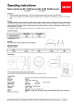
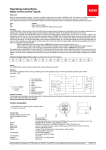
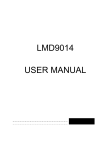
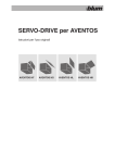
OPERATING INSTRUCTIONS
Battery indicators (= BI )
Please note!
Types 852 and 853
Read these instructions carefully. In the event of questions, please contact your
dealer or BAUSER directly.
Ensure that the installations and operating conditions described below are observed,
since otherwise you may lose your warranty rights.
These battery indicators are used for indication of the battery state of charge in large steps. Discharge indication is
made in three steps and advance warning is given to protect the battery from excessive discharge. On reaching a
battery residual capacity of app. 20 %, the red LED lights up and the relay contact opens (with type 852).
An integrated time delay avoids unwanted relay operation in case of high load during a short period of time.
The breaking voltage is at 1,8 V/C (e.g. 21,6 V for
the 24 V variant). This means that if the breaking
voltage drops below 1,8 V/C for a long time, the
relay contact opens (Type 852 resp.)
The time delay is between 1 min and 10 min,
depending on the discharge current and the
residual capacity.
State of charge
> app. 80 %
app. 40-80 %
app. 20-40 %
< app. 20 %
Switching threshold
Volt/Cell
> 2,02
2,02
1,96
< 1,80
Display
3 yellow LEDs
2 yellow LEDs
1 yellow LED
red LED
Cleaning of instrument if needed with a damp cloth and externally only. No other maintenance or servicing required.
Rear view:
Installation:
1.
Make mounting hole with Ø 52,5 mm.
5
2.
Remove milled nuts and mounting bracket from the battery indicator.
3.
Insert the battery indicator into the mounting hole from the front.
4.
Replace mounting bracket from the back,
screw on milled nuts and tighten.
1
2
3
4
Electrical connection:
The electrical connections are designed for tabs 6,3 mm (DIN).
Wiring no.
Designation
Polarity
1
2
3
4
battery
battery
relay contact (option: BI 852)
relay contact (option: BI 852)
+
+
-
(Pls. see type labels)
Note:
Cross section of
wires
min. 0,25 mm2
min. 0,25 mm2
min. 0,5 mm2
min. 0,5 mm2
When connecting the relay contacts ensure correct polarity!
Non-compliance may lead to excessive discharge of the battery!
Technical Data: (Types 852 and 853)
Battery types:
all standard battery types
Operating voltage:
12
24
36
48
72
80 VDC (depending on type)
Current consumption:
app. 35 m A (852 )
app. 20 m A (853)
EMC protection:
EN 50082-2
Relay contact:
1 make contact, max 120 VA loading capacity (Option: 1 NC contact)
Ambient temperature:
-25°C ... +70° C
Shock resistance:
IEC 68-2-32: 10 g
Vibration resistance:
IEC 68-2-6
Degree of protection (front):
IP 65 (DIN 40050)
Overvoltage class
II
BAUSER GmbH & Co KG
Julius-Bauser-Str. 40
D-72186 Empfingen
Phone (- - 49) 0 74 85/1 81-0
Fax (- - 49) 0 74 85/1 81-16
eMail: [email protected]
Internet: www.bauser-control.de
Operating_instructions_852_853.doc (04/07)