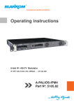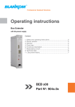
1
Professional Headend Solutions Operating instructions 8-fold IP-/ ASI-TV Modulator IP/ SFP/ ASI (H.264/ AVC, MPEG2) → ATV (8x AM) A-PALIOS-IPM4 Part No: 5105.43 5105.82 5105.83 5105.85 A-PALIOS-IPM4 8-fold IP-/ ASI-TV Modulator Part N : 5105.43/.82/.83/.85 IP/ SFP/ ASI (H.264/ AVC, MPEG2) → ATV (8x AM) o Content A LINE 1. Safety and operating instructions.............................................................................................................. 3 2. Device variants........................................................................................................................................... 3 3. Software options........................................................................................................................................ 3 4. General....................................................................................................................................................... 3 5. Main features.............................................................................................................................................. 3 6. Functional description................................................................................................................................ 3 7. Explanation of the operating elements...................................................................................................... 4 7.1 Front view....................................................................................................................................... 4 7.2 Meaning of the status LED‘s.......................................................................................................... 4 7.3 Rear view........................................................................................................................................ 4 7.4 Meaning of the LED‘s on rear........................................................................................................ 5 7.4.1 LED’s at the 10/ 100/ 1000 Mbit stream port 1........................................................................... 5 7.4.2 LED’s at the 10/ 100/ 1000 Mbit stream port 2 .......................................................................... 5 7.4.3 Status LED at the ASI socket...................................................................................................... 5 7.4.4 Status LED at the output coupler................................................................................................ 5 7.4.5 LED‘s at the 10/ 100 Mbit control port........................................................................................ 5 8. Setting by web interface............................................................................................................................ 6 8.1 Network connection to the computer............................................................................................ 6 8.2 Setting of individual parameters.................................................................................................... 7 8.2.1 Menu ”Overview”........................................................................................................................ 8 8.2.2 Menu “IP input”........................................................................................................................... 9 8.2.2.1 SFP option............................................................................................................................... 10 8.2.3 Menu ”Program”......................................................................................................................... 11 8.2.4 Menu ”Settings”.......................................................................................................................... 11 8.2.5 Menu ”Language”....................................................................................................................... 15 8.2.6 Menu ”Setup”.............................................................................................................................. 15 8.2.7 Menu ”Service”........................................................................................................................... 20 8.2.8 Menu ”Level”............................................................................................................................... 20 8.2.9 Menu ”Status”............................................................................................................................. 21 8.2.10 Menu „Amplifier“....................................................................................................................... 21 9. Factory settings.......................................................................................................................................... 22 10. Block diagram ......................................................................................................................................... 23 11. Application example................................................................................................................................. 23 12. Technical data.......................................................................................................................................... 24 13. Glossary................................................................................................................................................... 25 14. Bibliography............................................................................................................................................. 25 15. Notes on the device software................................................................................................................... 25 16. Document history..................................................................................................................................... 25 Declaration of conformity......................................................................................................................... 26 2 A-PALIOS-IPM4 8-fold IP-/ ASI-TV Modulator Part No: 5105.43/.82/.83/.85 IP/ SFP/ ASI (H.264/ AVC, MPEG2) → ATV (8x AM) 1. Safety and operating instructions A LINE When installing, starting-up and adjusting the devices, it is necessary to consider the system specific references in the instruction manual. The devices may only be installed and started up by authorized technical personnel. When installing the devices into the receiving points, the adherence of the EMC regulations is to be ensured. The installing and wiring have to be done without voltage. With all work the defaults of the DIN EN 50083 have to be considered. It is especially important to follow DIN EN 60728-11[2]. If installed in mounting cabinets adequate air circulation must be guaranteed. The mounting in closed cabinets without sufficient air flow is not allowed. The devices are rated protection classification I. Therefore it is absolutely necessary to insert the mains plug into a socket with protective contact. 2. Device variants A-PALIOS-IPM4 A-PALIOS-IPM4 A-PALIOS-IPM4 A-PALIOS-IPM4 5105.43 IP/ SFP/ ASI (H.264/ AVC, MPEG2) → ATV (8x AM) incl. amplifier & 2x hot plug PSU 5105.82 IP/ SFP/ ASI (H.264/ AVC, MPEG2) → ATV (8x AM) 5105.83 IP/ SFP/ ASI → ATV incl. amplifier & 2x PSU (75 Mbit input data rate) 5105.85 IP/ SFP/ ASI → ATV incl. amplifier & 2x PSU (300 Mbit input data rate per channel, overall max. 500 Mbit) 3. Software options CKB 201 CKB 202 CKB 207 CKB 210 CKB 211 CKB 216 CKB 227 5100.51 5100.52 5100.57 5100.60 5100.61 5100.65 5100.67 activation test lines activation subtitles activation BISS-Function activation SFP-Port activation ASI-Port activation AC3/ Dolby Digital activation marquee 4. General The SAT-TV Transmodulator A-PALIOS-IPM4 is a device of the head end system A-LINE, which is conceived as a complete system for big and middle sized networks. The A-PALIOS-IPM4 selects eight programs from up to eight fed-in IP transport streams or from an ASI transport stream and converts these into analogue TV signals to transmit it into the cable networks. In this case, a maximum of eight analogue television channels is generated from the available H.264/ AVC or MPEG2 transport streams. 5. Main features • 8x IP SPTS/ MPTS input • IP streaming via RJ45 or SFP with redundancy • 1x ASI input • MPEG 2/4 HD/ SD decoding • multi-standard PAL modulator • IEdge signal processing • RF output switchable as single or with loop • control of the device via HTML or SNMP 6. Functional description The device receives a data stream via Gigabit Ethernet. It can receive up to eight transport streams from the included IP encapsulated transport streams. The eight transport streams are further processed in eight H.264/ AVC & MPEG2 decoders. A high-performance FPGA does the analogue TV modulation and the freely adjustable up-conversion into the cable network range (45 ... 862 MHz). The eightfold modulator is adjacent channel compatible. A high-speed digital→analogue converter (DAC) is responsible for the excellent output signal. After amplification and sum level adjustment, the cable signal is coupled through a directional coupler to the output jacks. The A-PALIOS IPM4 offers the possibility to decode Dolby 2 audio streams. 2 Dolby - registered trademark of Dolby Laboratories, Inc. 3 8-fold IP-/ ASI-TV Modulator A-PALIOS-IPM4 Part N : 5105.43/.82/.83/.85 IP/ SFP/ ASI (H.264/ AVC, MPEG2) → ATV (8x AM) o 7. Explanation of the operating elements A LINE 7.1 Front view Status LED „POWER“ Test (-20dB) 1 1 Status LED „SYSTEM“ Status LED‘s channel 2, 4, 6, 8 Status LED‘s channel 1, 3, 5, 7 only available for device variants 5105.43/.83/.85 7.2 Meaning of the status LED‘s Designation Color Status Meaning of display POWER green permanently on device is on flashing only one power supply is working permanently on device is in standby off device is off, operating voltage is not applied permanently on device is ready flashing software update is running permanently on temperature is high, fan is activated flashing temperature is critical, the device will no longer work or is forced to shut down off device is not ready green permanently on channel operates without error amber permanently on error warnings, depending on signal: - input and/ or output without sync - input sync, but in bad quality (eg. mosaic effect in the TV picture) flashing hardware is faulty off channel is off amber SYSTEM green amber CH 1 ... CH 8 7.3 Rear view Ground terminal POWER RF output (Redundancy) amplifier 2 2 Stream port 1 Stream port 2 (RJ45)+LED‘s (SFP) Fan Stream port 2 LED‘s „Link/Traffic“+„1G“ ASI input only available for device variants 5105.43/.83/.85 4 ASI LED Control port Output coupler „Status“ incl. LED‘s „Input“ „Output“ RF input amplifier 2 Status LED Reset button „LOOP“ at the output coupler Fan A-PALIOS-IPM4 8-fold IP-/ ASI-TV Modulator Part No: 5105.43/.82/.83/.85 IP/ SFP/ ASI (H.264/ AVC, MPEG2) → ATV (8x AM) 7.4 Meaning of the LED‘s on rear A LINE 7.4.1 LED’s at the 10/ 100/ 1000 Mbit stream port 1 Designation, color Status Meaning of display GbE connect LED, green permanently on only illuminated when the connection is a GbE connection (does not light up at a 10/ 100 Mbit connection) off no GbE connection permanently on cable connection is established flashing data is received off no cable connection Connect/ data LED yellow 7.4.2 LED’s at the 10/ 100/ 1000 Mbit stream port 2 Designation Color Status Meaning of display 1G green permanently on only illuminated when the cable connection is a GbE connection (does not light up at a 10/ 100 Mbit connection) off no GbE connection LINK/ TRAFFIC amber permanently on cable connection is established flashing data is received off no cable connection or option is not enabled 7.4.3 Status LED at the ASI socket Designation Color Status Meaning of display STATUS green permanently on ASI transport stream is present flashing no ASI transport stream off option is not enabled 7.4.4 Status LED at the output coupler Designation Color Status Meaning of display LOOP green permanently on loop active, i.e. nominal level range 64 ... 82 dBµV off no loop, i.e. nominal level range 76 ... 94 dBµV 7.4.5 LED‘s at the 10/ 100 Mbit control port Designation, color Status Meaning of display Connect LED, yellow permanently on network cable is connected off no cable connection flashing data is exchanged off no data exchange Data LED, green 5 A-PALIOS-IPM4 8-fold IP-/ ASI-TV Modulator Part N : 5105.43/.82/.83/.85 IP/ SFP/ ASI (H.264/ AVC, MPEG2) → ATV (8x AM) o 8. Setting by web interface A LINE To use all functions of the device activate Java Script in your browser settings. Settings via checkbox are applied immediatelly, but not stored in memory! So they would be lost on a possible restart of the device. To save these settings the “send“ button must be pressed. Please send and store your settings by pressing the „send“ button after each change. 8.1 Network connection to the computer System requirements: - PC/ laptop with 10/ 100 Mbit Ethernet interface - Internet browser (e.g. Windows Internet Explorer), capable JAVA script Setup the connection: The A-PALIOS-IPM4 has to be connected to PC network using an Ethernet cable. The default IP address of the device is 192.168.1.100. In order to access the web interface of the A-PALIOS-IPM4 from a PC, the PC has to be in the same subnet (192.168.1.XXX; subnet mask 255.255.255.0), where XXX is not used by any other device in this subnet. If multiple A-PALIOS-IPM4 are connected to the same network each device must be set to its own unique IP address to avoid address conflicts. After these settings, the IP address of the PC has to be adjusted to match the network. Now the devices can be accessed via browser with the new IP address. If activated (»Setup→GUI Settings→Activate user and keyword check) the user has to log in now ( »chapter 8.2.6). After successful registration or a connection establishment without password (default setting) the start page of the device is displayed ( »chapter 8.2.1). 6 A-PALIOS-IPM4 8-fold IP-/ ASI-TV Modulator Part No: 5105.43/.82/.83/.85 IP/ SFP/ ASI (H.264/ AVC, MPEG2) → ATV (8x AM) 8.2 Setting of individual parameters A LINE Here you can set certain parameters of the device or perform configurations. The various setting menus can be selected in the navigation tree on the left side. The setting is supported by an online help. If you mouse over a parameter explanations of this parameter are displayed in an orange colored text box in the lower part of the screen. By setting in the “Setup“ menu ( »chapter 8.2.6) may be selected so that the help appears in the status bar of your browser. If appropriate setting changes in the browser options are necessary. By default status information for the device are displayed below the navigation tree. An option to move it on the right side instead is available ( »chapter 8.2.6). All eight channels are listed individually. A green LED symbol in front of “channel 1 ... 8“ means that input and output are synchronized and that the channel operates without error. An orange colored symbol indicates that an error has occurred in that channel. An overview of the status of various parameters of the channel is obtained by clicking the corresponding channel. A transparent LED symbol means that the channel is not configured or the RF output is turned off. If you click the channels an overview window is displayed. The pop-up window closes after 20 seconds or by cklicking in its lower part. The “Power“ LED indicates the connection status between the network interface and the device. The “System“ LED gives an overview over the status of system parameters of the device. In all menus it‘s possible to switch the language between German and English on the top of the right side. 7 A-PALIOS-IPM4 8-fold IP-/ ASI-TV Modulator Part N : 5105.43/.82/.83/.85 IP/ SFP/ ASI (H.264/ AVC, MPEG2) → ATV (8x AM) o 8.2.1 Menu ”Overview” A LINE This page provides a status overview of the eight channels. If a channel is working without errors, “SYNC“ is displayed. If the RF power is turned off, the display “Off“ appears behind the respective channel. Below the staus window all devices belonging to the headend are listed (»Setup chapter 8.2.6). Functions across devices like the NIT exchange between devices of the QAMOS group can be done on all listed devices. The individual components of a headend are listed with their IP address. The IP address is a link, so you can switch to the next device. If no headend was configured, a “Search“ button is displayed. It opens the “Setup“ menu and scans the network for other A-LINE-SBL and SBL devices. Then all available devices are listed. They can be selected and added to the headend. By clicking the “Logout“ button the user is logged out and the login window is displayed. 8 A-PALIOS-IPM4 8-fold IP-/ ASI-TV Modulator Part No: 5105.43/.82/.83/.85 IP/ SFP/ ASI (H.264/ AVC, MPEG2) → ATV (8x AM) 8.2.2 Menu “IP input” A LINE This is the menu for the network configuration of the streaming port and the eight IP transport streams, from which the eight desired programs for transmitting can be selected. First the configuration options for the two stream ports are displayed.Stream port 2 is only available after enabling the software option (»chapter 8.2.6). The IP address, subnet mask and gateway is configured for each port. The next step is to configure the setup parameters of the eight IP input transport streams (IP input channels). Again, IP address, port and transport protocol (UDP or RTP) have to be entered for each IP channel. When using IGMPv3 it can be specified, from which source the multicast stream is desired. For this purpose, enter the appropriate source filter address. Press the “send“ button to save the settings. Unused ports are disabled by entering the IP address 0.0.0.0. Identical settings within these 8 IP channels are not allowed and automatically marked red. Note: Some switchesapply configuration changes for the multicast group after the set query interval has expired. Some switches ignore unsolicited IGMP join message. If the querier in the switch is set to a longer interval, the switch might ignore the emitted IGMP message and thus the srtream is not transmitted instantly after the configuration changed. Upon expiration of the query interval, the switch checks its membership in multicast groups. The device responds. The response is accepted by the switch, which then transmits the stream to the device. 9 A-PALIOS-IPM4 8-fold IP-/ ASI-TV Modulator Part N : 5105.43/.82/.83/.85 IP/ SFP/ ASI (H.264/ AVC, MPEG2) → ATV (8x AM) o 8.2.2.1 SFP option A LINE The SFP option allows the connection of different devices to the IP input. Depending on the SFP device various management and media types can be connected to the A-PALIOS-IPM4. So the IP input can be expanded by another IP data source. The SFP device requires stream port 2, with the result that either “Stream port 1“ or “Stream port 2“ can be used as an IP input. One of the two IP inputs can be defined as the preferred source and the other IP input as redundancy source. If an IP data source fails, it‘ll switch to the other data source. Individual rules can be defined. First you have to decide whether an IP input channel is included in the monitoring. In addition, you have to choose when to switch: either when one input channel fails or when all monitored channels are failing. The switching will occur even no signal is present on the redundancy input. The switch back to the preferred IP input is not automatically. It has to be done manually via the user interface. Note that an automatic switch based on the defined rules will not occur until data was received on the monitored channels once. In the mask of the network settings the option of selecting the preferred IP input is displayed. The selection is done by pressing the respective option button. Select the line „error check of the channels“ as described above. Choose “or“ to perform the redundancy switchover if any one of the monitored channels is failing. Choose “and“ to perform the redundancy switchover if all monitored channels fail. The checkbox on the right side marks if the channel is included in the monitoring. 10 A-PALIOS-IPM4 8-fold IP-/ ASI-TV Modulator Part No: 5105.43/.82/.83/.85 IP/ SFP/ ASI (H.264/ AVC, MPEG2) → ATV (8x AM) 8.2.3 Menu ”Program” A LINE This is menu for the program selection of the output channels. The current channel allocation of the A-PALIOS-IPM4 device is listed. The following settings per channel are available: • column Input Select the transponder • column Program Select the preferred program of the transponder. If the program is available in multiple languages, specify language and subtitle in the next two colums. • column Output frequency Set the channel for the selected program. Double allocation of the eight output channels is checked automatically. Use the check box “RF“ to set the RF output to “on“ or “off“. Press the button Program search to read the list again. 8.2.4 Menu ”Settings” Each channel can be adjusted to your individual requirements. The channels is selected by either clicking left in the navigation tree or by clicking on the tabs above the setup tables. 11 A-PALIOS-IPM4 8-fold IP-/ ASI-TV Modulator Part N : 5105.43/.82/.83/.85 IP/ SFP/ ASI (H.264/ AVC, MPEG2) → ATV (8x AM) o The following parameters are adjustable: A LINE Program list (Transponder) If “Program selection with select box“ in Setup → GUI settings is deactivated ( »chapter 8.2.6), the screen at the left for program selection is displayed. All programs of the selected transponder are listed with name and service ID. The selection of the program is done by marking the respective select box. The program name and the other parameters of the program are applied automatically. In this case the program name in the menu “Selected program“, variant 1 is not selectable. Input input parameters of the channel Input name Input e.g. name of the program, editable selection: IP input channels 1 ... 8, ASI input Selected program variant 1: program selection menu Program name selection of the program from the program list of the transponder of the selected IP TS Service ID displays the service ID of the selected program Load reloads the program list Type displays the type of the program Languageselection of the available language Direct input selection menu, manual input (see below) Selected program variant 2: manual input Program name displays the name of the program, which was selected in the input menu Load reloads the program list Service ID service ID of the requested program, range: 0...65535 Type selection of the program type: TV, Radio Languagelanguage number, range: 0 ... 255 Output output parameters of the channel Frequency input Output frequency Output level offset RF signal Sound carrier 2 selection: channel, frequency 1 selection from channel table/ input in kHz 1 level offset 2 display selection: On, Off (Off at Time control „off“) adjustable in Setup menu for all channels If frequency input “channel“ is selected, the output frequency can be chosen from a preselected channel ( » GUI settings chapter 8.2.6). If “frequency“ is selected, then the output frequency is selectable in kHz steps. 2 Adjustment of the offset of each channel to the basic level ( » GUI settings chapter 8.2.6) 1 Video setting of the video parameters Video output selection: On, auto Off, auto color bar, auto color bar with test tone Color bar selection: On, On with test tone, Off Color system adjustable in Setup menu for all channels Video format selection: 4/3, 14/9, 16/9 Scaling method selection: none, pillar or letter box, Pan & Scan selection 2: dynamic, fullscreen 3 3 only selectable in mode “Pan & Scan“ 12 A-PALIOS-IPM4 8-fold IP-/ ASI-TV Modulator Part No: 5105.43/.82/.83/.85 IP/ SFP/ ASI (H.264/ AVC, MPEG2) → ATV (8x AM) Audio A LINE setting of the audio parameters Audio gain adjustment range: -20 ... +18 dB Audio mode 1 selection 1: mono L, mono R, dual, dual invers, stereo, auto 3 selection 2: mono L, mono R, mono L+R, auto 4 3 if sound carrier 2 is set to “analog“ ( » GUI settings chapter 8.2.6) 4 if sound carrier 2 is set to “Off“ ( » GUI settings chapter 8.2.6) Audio mode NICAM 2 NICAM gain 2 1 2 selection: auto, stereo, dual adjustment range: -20 ... +18 dB if sound carrier 2 is set to “analog“ or “Off“ ( » GUI settings chapter 8.2.6) if sound carrier 2 is set to “NICAM“ ( » GUI settings chapter 8.2.6) VPS setting of the VPS parameters CNI code 5 adjustment range: 0x000…0xFFF (hexadec.) Source PIL 5 selection: A056(PDC), A056, PDC, TimerControlCode Mode On, Off 5 only adjustable in standards B/G and D/K Subtitling 6 adjustment of the subtitle Mode selection: Off, Teletext, DVB Settings DVB subtitling DVB language index Use extended ID‘s adjustment range: 0...255 selection: yes, no Settings teletext subtitling Teletext page Language mode 6 adjustment range: 0..65535 selection: West, East, Russian, Arabic, Farsi only available, if “Subtitling“ option is enabled ( »chapter 8.2.6) Test lines 7 The A-PALIOS-IPM4 offers the opportunity to output test signals on up to 12 image lines from the following selection: Off, CCIR 17, CCIR 18, CCIR 330, CCIR 331, Sin(x)/ x, Ramp. As a default, the image lines 17, 18, 330 and 331 are selected. The image lines selection is editable, i.e. the test lines can be output on each image line in the range 1..625. 7 only available, if “Test line“ option is enabled ( »chapter 8.2.6) Decryption settings 8 BISS key BISS-E injected ID input 8 input of the 12-digit code in BISS mode 1 or of the 16-digit code in BISS mode E input of the 14-digit code in BISS mode E, no in BISS mode 1 only available, if “BISS“ option is enabled ( »chapter 8.2.6) Complementary data Teletext selection: On, Off WSS insertion selection: On, Off SECAM impulses 9 selection: On, Off 9 only selectable, if color standard SECAM is set ( »chapter 8.2.6) 13 A-PALIOS-IPM4 8-fold IP-/ ASI-TV Modulator Part N : 5105.43/.82/.83/.85 IP/ SFP/ ASI (H.264/ AVC, MPEG2) → ATV (8x AM) o Time Control A LINE click the check box, to (de-)activate the functions Switch ON Switch OFF select the weekday mode (Mo, Tu, ... Su); Mo to Fr; Mo to Sa; Sa to Su and daily and start time select the shutdown date and time Marquee 10 Use the checkbox (de-)activates the marquee Position positions the text between 5 ... 100% of the vertical position on the screen Text color available in black or white Background color color setting of the font background, based on the selected font color or transparent Text the content of the marquee Speed speed level of the marquee 10 only available, if “Marquee“ option is enabled ( »chapter 8.2.6) 14 A-PALIOS-IPM4 8-fold IP-/ ASI-TV Modulator Part No: 5105.43/.82/.83/.85 IP/ SFP/ ASI (H.264/ AVC, MPEG2) → ATV (8x AM) 8.2.5 Menu ”Language” A LINE In this menu the user interface language can be set. You can choose between German and English. The adjustment can be made either in the navigation tree at the point “language“ or on the top right via the language selection box. 8.2.6 Menu ”Setup” In this menu, various administrative and system settings can be made. 15 A-PALIOS-IPM4 8-fold IP-/ ASI-TV Modulator Part N : 5105.43/.82/.83/.85 IP/ SFP/ ASI (H.264/ AVC, MPEG2) → ATV (8x AM) o Specifically, the following can be configured: A LINE GUI settings Help information within the status line of the browser By default, the online help is displayed in an orange colored text box at the bottom of the page. If this option is selected, the help texts are displayed in the status bar of your browser instead (must be allowed in the browser settings). Display all system files By default “System administration→Backup“ all system files are up- / downloaded as a single file. By selecting „display all system files“ all system files are displayed. Now specific files can be selected for up- / download. Display tabs By default, the tabs are shown in the upper part of the user interface. Unselect this option to remove them. Display status on the right side By clicking the box, the status of the channels and the system is shifted to the right of the user interface. Optimization for low-speed data connectivity Selecting this option reduces the image size to accodate a low-speed data connection (GSM). Output frequency raster Availabe options are: B/G, D/K, M and L raster. In case of D/K1 the sound carriers are at 6,5/ 6,25 MHz, D/K2 at 6,5/ 5,74 MHz and D/K3 at 6,5/ 6,74 MHz, the raster for M is at 6 MHz and for L at 8 MHz. Based on this selection the group delay filter is set for standard B/G, D/K, M or L raster. The NICAM sound carrier is 5.85 MHz and is selectable for the standards B/G, D/K 2 and L. Color System You can choose between PAL, SECAM and NTSC. Sound carrier 1 and 2 level attenuation The setting for the audio carrier 1 is -10 ... -19 dB, for the sound carrier 2 is -17 ... -26 dB (analog) repective -15 ... -30 dB (NICAM). Sound carrier 2 Here you can select whether the sound carrier2 is off or is on as an analog or NICAM carrier. Dolby Mode Only available if the software option „Dolby mode“ is enabled (»enabling of). Choose beween: Auto - automatic setting Stereo / Pro Logic Mode 1 L t / R t - Pro Logic Mode 2 L 0 / R 0 - Stereo Carrier mode Unmodulated signal for testing. Fan mode Available settings are from automatic mode to permanent ON. Program selection with select box If is deactivated, the program selection is done via program list in the adjustment menu. Otherwise the program selection is done in the field “Selected program“ (»chapter 8.2.4). Activate user and password check This option can only be deactivated by the administrator. If disabled, no login is required ( »chapter 8.1). SBL headend Lists all A-LINE-SBL and SBL devices, which are found in the same network. By pressing the “Search“ button the list is updated. All marked devices belong to the headend and are displayed on the “Overview“ page. 16 A-PALIOS-IPM4 8-fold IP-/ ASI-TV Modulator Part No: 5105.43/.82/.83/.85 IP/ SFP/ ASI (H.264/ AVC, MPEG2) → ATV (8x AM) A LINE System administration By default the short list is displayed (see first picture). Backup The default is to save or load the complete configuration. If under “GUI setup→Display all system files“ is selected, all system files are listed. The system files can also be loaded or saved separately (see figure below). Update Click the „Load“-Button to load a software update. The button “View logbook“ leads to an overview, in which all the processes have been documented since the start of the GUI. Each operation is listed by date, time and description. If operations have been executed, the logged on user, who initiated the action, is saved too. By pressing of the “Erase“ button all entries are deleted, only possible by the administrator. System Location In this field a name for the A-PALIOS-IPM4 can be entered to identify the device easily. The name will appear on the top right of the website below the language selection box. It is provided via SNMP: Iso(1)org(3).dod(6).internet(1).mgmt(2). mib.2(1).system(1).sysLocation(6). Logout restarts the user interface Default reset to factory default Reboot restart of the A-PALIOS-IPM4 Enabling of Possible software options for the A-PALIOS-IPM4 can be enabled. The registration code must be entered in the input field and by pressing the “Send“ button. Activated options are displayed in black, inactive are grayed out. 17 A-PALIOS-IPM4 8-fold IP-/ ASI-TV Modulator Part N : 5105.43/.82/.83/.85 IP/ SFP/ ASI (H.264/ AVC, MPEG2) → ATV (8x AM) o A LINE Date and time Clicking the “Set“ button, the date and time will be set to that of the PC. Settings of the web interface The A-PALIOS-IPM4 supports the DHCP functionality. DHCP-Client is factory default. Note, that after each factory reset the A-PALIOS-IPM4 is set to “DHCPClient“. If the DHCP functionality is set to “Off“, the appropriate fields for IP number, subnet mask and gateway can be set manually to fit the network. If the device is set as “DHCP-Client“, it automatically obtains an IP address from the DHCP server on the network. The manual network settings are disabled. By pressing the “Info“ button the automatically assigned network configuration of the device is displayed. Close the window by clicking in its lower area or wait 20 seconds. Please note: if the device is set as “DHCP-Server“, the IP address 192.168.1.100 must not be set. If you select this address an error message will be displayed. In addition to the IP settings, you can configure the DHCP range from which the connected client IP addresses are assigned. The address range has to match the IP address and subnet mask of the server and should not be too small. The default is 192.168.1.1 to 192.168.1.99. Along with the DHCP server a local DNS (Domain Name Server) will be set up. To use it in full extent a connected PC/ laptop must be configured as a DHCP client. Note that, using Windows, not only the IP address but also the DNS server address has to be obtained automatically. If the device is configured as a DHCP server or client and the client has received an IP address successfully, the device can be accessed via a web browser using its name. This name is composed of the prefix “sbl“ and the device number that is printed on the back of the device and on the packaging. For example, the device with the number 0123456 can be found under “sbl0123456“. It might be necessary to add the domain name. In case that the device was configured as a server, the name of the domain is “sbl0123456.sbl“. If another DHCP server is used, ask your administrator for the domain name. An example for the simplification of the configuration or operation of the headend via DHCP is, that an A-LINE-SBL device is configured as a server, the remaining devices and the connected PC/ laptop are configured as a client. By calling “dhcp.sbl“ in the browser the GUI of the server device is loaded. Now the headend can be read. So all connected components are found and listed. The headend can now be stored in the Setup→System administration. By selecting the respective devices link in the headend overview, you can switch to the other devices user interface quickly. 18 A-PALIOS-IPM4 8-fold IP-/ ASI-TV Modulator Part No: 5105.43/.82/.83/.85 IP/ SFP/ ASI (H.264/ AVC, MPEG2) → ATV (8x AM) SNMP option A LINE The SNMP settings are only available after the “SNMP“ option was enabled (»Enabling of). First section: The “Mode“ selection field enables or disables the SNMP functionality, including the sending of traps. The selector “Version“ sets the SNMP version (version 1, 2 or 3). In the two fields below, the reading and writing via SNMP is separately indicated for the versions 1 and 2. In version 3, these two fields are disabled. Here, all registered users of the device (GUI Settings→Passwords) have the automatic read access to SNMP. The write access can be enabled or disabled for each user by clicking the SNMP check box in the “Passwords“ menu. By clicking the “MIB“ button the MIB of the device is generated and can be downloaded. Second section: The trap settings are done here. First select the trap version: V1 trap normal traps according to SNMPv1 with specified community V2 trap normal traps according to SNMPv2 with specified community V2 inform sends information traps according to SNMPv2 and waits for an acknowledgement V3 trap normal traps according to SNMPv3 V3 inform sends information traps according to SNMPv3 and waits for an acknowledgement In traps of version 1 and 2 the community can be configured. In traps of version 3 you can configure the user/password and the usage of the network MAC address as engine ID. These settings must correspond with the configuration of the trap receiver, so that traps are successfully transferred. For this purpose a test trap can be sent by clicking the button “Test“. If a test trap triggered, all pre-preserved traps are discarded. Up to 256 IP addresses can be created resp. unlocked to receive the traps.These are listed under “Receiver IP“. Third section: events are configured, whether they (and with which thresholds) trigger traps. There are three ways to configure a trap: • without parameters, e.g. fan on/ off • with a free selectable parameter for a medium priority • with a selectable parameter from a list box for a medium priority Events Events leading up to trigger an SNMP trap, can be (de-) activated and their parameters can be configured. References and notes: All users using SNMPv3 must use passwords with at least 8 characters. For SNMPv3 the A-LINE-SBLsupports only the authentication password, not the privacy password. The A-LINE SBL only supports the MD5 algorithm for authentication password in SNMPv3. Information traps are specific traps that are available since SNMPv2.If the sender gets no “acknowledge“ from the receiver, it will retransmit until the “acknowledge“ is received. An A-LINE SBL device keeps up to 256 information traps that were not sent successfully. If there are more unconfirmed traps, the older traps are discarded and marked in the logbook as “failed“. A successfully sent trap is also registered in the logbook. In case of power failure or reboot of the device the non-confirmed traps are lost. You‘ll find details in the help text for each event. The critical priorities are set to fixed values that can not be changed. If the web interface of A-PALIOS-IPM4 device is open, no changes are possible via SNMP. Passwords This setting will only appear when you are logged in as administrator, who has the permission to make administrative changes. In addition the check box “GUI settings→User and password check“ has to be enabled. The user ID and password for the administrator can be set in the first line. Up to 8 users and passwords can be created. non-admin users have read-only rights. The default password for the admin is: and for users: 1111 0000 If the SNMP option is enabled, for each user a SNMP check box will be displayed. By clicking the box you assign the writing rights for individual users, available since SNMP version 3 (»section SNMP option). 19 A-PALIOS-IPM4 8-fold IP-/ ASI-TV Modulator Part N : 5105.43/.82/.83/.85 IP/ SFP/ ASI (H.264/ AVC, MPEG2) → ATV (8x AM) o 8.2.7 Menu ”Service” A LINE Here you‘ll find all service information for the A-PALIOS-IPM4: the BLANKOM service hotline and e-mail address, the manual as pdf file and a link to the BLANKOM homepage where the latest software release is available. Also the currently installed software release is displayed. 8.2.8 Menu ”Level” In the first section you can enable or disable the loop through output. If enabled, select the nominal level for all 8 channels in the range from 64 ... 82 dBµV. If the loop is disabled, the output level of the 8 channels can be set in the range of 76 ... 94 dBµV. The device variants 5105.43/.83/.85 includes an amplifier. If this amplifier is used in the internal SBL mode, it is fixed at +21 dB. The level selection can be set automatically in a range between 94 ... 115 dBµV (»chapter 8.2.10 “Amplifier“). Furthermore each channel can be set individually with an offset of +3 ... -6 dB in 0.5 dB steps. The buttons simplify the offset level setting if you want to make the same adjustments for all 8 channels. The left button increases the offset by 0.5 dB, the right button decreases it by 0.5 dB. With the middle button you‘ll set the offset of all 8 channels to 0 dB. 20 A-PALIOS-IPM4 8-fold IP-/ ASI-TV Modulator Part No: 5105.43/.82/.83/.85 IP/ SFP/ ASI (H.264/ AVC, MPEG2) → ATV (8x AM) 8.2.9 Menu ”Status” A LINE It shows an overview of the status of the various components per channel, updated every 5 seconds. Listed are only the current values. mouse over the parameter to display its name in the help box or in the status bar of the browser (according to your configuration). The listing is in 3 groups: input, modulators and system. With the drop-down menu at the top right, you select whether you get an overview (all) or if only one of the three groups is displayed. 8.2.10 Menu “Amplifier“ The amplifier can be set and used independently of the A-PALIOS-IPM4. It does not influence the device itself or other devices of the headend. The adjustment range of amplification is between 15 .... 35 dB. • amplifier deactivated: power consumption 0 W output level with loop 64 ... 82 dBµV without loop 76 .... 94 dBµV • amplifier activated: power consumption +14W output level without loop 76 ... 94 dBµV + amplification (15 ... 35) • internal SBL mode The amplifier is fixed at +21 dB and is automatically integrated into the level display menu. Thus the max. output level is at 118 dBµV. In view of the deterioration of the signal to noise ratio the use of loop is not recommended. • Set reference The actual applied level is set as a reference. The status menu displays the level deviation of a value during operation. 21 A-PALIOS-IPM4 8-fold IP-/ ASI-TV Modulator Part N : 5105.43/.82/.83/.85 IP/ SFP/ ASI (H.264/ AVC, MPEG2) → ATV (8x AM) o 9. Factory settings A LINE A short pressing of the reset button on the front of the device causes a reboot, i.e. the device restarts and all stored values are restored. If the device must be reset to factory settings, please press the reset button until the “POWER“ and “SYSTEM“ LED will illuminate green permanently again. This process takes about 15 seconds. The factory settings are: Input parameters Output parameters Setup settings Output level Network settings 22 8-fold IP-/ ASI-TV Modulator A-PALIOS-IPM4 A Part No: 5105.43/.82/.83/.85 IP/ SFP/ ASI (H.264/ AVC, MPEG2) → ATV (8x AM) 10. Block diagram Stream port 1 (RJ 45) GigE PHY Stream port 2 (SFP) LINE Frontend 8x TS 8x ASI MPEG 2/4 Decoder 8x Eth. Control CPU Stratix IV FPGA MOD NIOS UPC RF DAC 12 V SDRAM _ RF DDR 2 FLASH ~ -20dB Power supply unit Supply (redundancy) RF 1) 1 only available for the device variants 5105.43/.83/.85 F SFP ASI-TS IN A-PALIOS-IPM4 SFP IP-TS IN2 CONTROL CONTROL IN ASI-TS IN A-PALIOS-IPM4 SFP IP-TS IN2 IP-TS IN1 OUT CONTROL IN ASI-TS IN F A-PALIOS-IPM4 SFP IP-TS IN2 IP-TS IN1 OUT ASI-TS IN F A-PALIOS-IPM4 IP-TS IN2 IP-TS IN1 CONTROL IN Output PAL 81 dBµV Feed ASI signal Feed IP stream Management Feed ASI signal Management Feed IP stream Management Feed IP stream Management 11. Application example OUT IP-TS IN1 IN OUT A-PALIOS-IPM4 A-PALIOS-IPM4 A-PALIOS-IPM4 A-PALIOS-IPM4 192.168.1.101 192.168.1.102 192.168.1.103 192.168.1.104 23 8-fold IP-/ ASI-TV Modulator A-PALIOS-IPM4 A Part N : 5105.43/.82/.83/.85 IP/ SFP/ ASI (H.264/ AVC, MPEG2) → ATV (8x AM) o 12. Technical data Signal quality C/N in channel (BW = 4.8 MHz) S/N ratio parallel sound (unweighted/ weighted) Spurious 45...862 MHz Max. frequency stability Output level stability IP input (stream port) Network connection (LAN/ WAN) Ethernet,10/ 100/ 1000 Base-T Connector 1x RJ 45, 1x SFP Protocols ARP, IGMPv3, UDP, RTP max. IP data rate total 800 Mbps per channel 5105.43/.82/.83 75 Mbps per channel 5105.85 300 Mbps 1 ASI input Level range Data rate Connector Impedance ASI polarity 200 … 880 mVpp 270 Mbps BNC socket 75 Ω regular/ inverted ASI signal processing Data rate 5105.43/.82/.83 5105.85 ASI transfer format TS transfer format Signal processing 0,625 ... 75 Mbps 0,625 ... 213 Mbps continuous, burst 188, 204 Byte EN 50083-9 [1] MPEG decoder Video Audio H.264/ AVC Level 4.1 HP, MPEG-2 MP@HL MPEG-1 Layer 1&2, AAC, AC32 RF parameters amplifier Number of inputs Frequency range Impedance Connector Max. amplification Max. input level Operating input level Frequency response Test output Max. output level Operating output level Level adjusting range Level step size Return loss input output TV output TV standard B/G, D/K, L, M sound type B/G, D/K double carrier FM, NICAM M mono carrier FM L mono carrier AM, NICAM sound carrier frequencies B/G 5,5/ 5,742 MHz to the picture carrier 5,85 MHz (NICAM) D/K1 6,5/ 6,25 MHz D/K2 6,5/ 5,742 MHz 5,85 MHz (NICAM) D/K3 6,5/ 6,742 MHz L 6,5 MHz 5,85 MHz (NICAM) sound mode B/G, D/K analog mono, stereo, dual, auto (VPS controlled) NICAM stereo, dual, auto M analog mono L analog mono NICAM stereo, dual, auto Audio deviation B/G, D/K 50 kHz Audio deviation mono carrier M 25 kHz Output frequency range 45 ... 862 MHz Tuning step 1 kHz Max. output level 97 dBμV (per channel) Total level settings without loop 76 ... 94 dBµV (1 dB steps) with loop 64 ... 82 dBµV (1 dB steps) Individual level settings (offset) +3 ... -6 dB (0.5 dB steps) Channel allocation adjacent channel ability Connector F socket Impedance 75 Ω Return loss ≥ 18 dB 45 MHz - 1.5 dB/ octave 1 total data rate of all channels, ASI must not exeed 500 Mbps 2 only available if the software option „Dolby Mode“ is enabled Operating parameters Operating voltage 5105.43 5105.82/.83/.85 Power consumption without amplifier with amplifier LINE ≥ 65 dB ≥ 65/ 60 dB ≥ 60 dB 30 kHz ± 0.5 dB 1 45 ... 1006 MHz 75 Ω F socket 35 dB 104 dBμV 70 ... 90 dBμV ± 1 dB - 20 dB 128 dBμV according EN 50083-5, Pos. 3.2 [5] 108 dBμV accord. CENELEC 42 channels, flat, CTB = -72 dB 15 ... 35 dB 1 dB > 14 dB ≥ 18 dB 45 MHz - 1.5 dB/ octave 2x 90 ... 240 V~ 50/ 60 Hz or 2x 48 V DC (36 ... 72 V) or 1x 90 ... 240 V~ 50/ 60 Hz 1x 48 V DC (36 ... 72 V) including redundancy function 2x 90 ... 240 V~ 50/ 60 Hz including redundancy function 49 W 63 W Environmental conditions Temperature range -10 ... +55 °C Temperature range for data keeping 5 ... 45 °C Relative humidity ≤ 80 % (non condensing) Method of mounting horizontal Location of mounting splash-proof and drip-proof 24 Miscellaneous Dimensions (l x w x h) Weight 5105.43 5105.82 5105.83/.85 448 x 44 x 350 mm 6.000 g (without PSU) 6.100 g 6.400 g Delivery content 5105.43/.83/.85 2x power cord 1x RJ45 connection cable 1x terminating resistor 1x mounting kit 1x F jumper cable (180 mm) 8-fold IP-/ ASI-TV Modulator A-PALIOS-IPM4 Part No: 5105.43/.82/.83/.85 IP/ SFP/ ASI (H.264/ AVC, MPEG2) → ATV (8x AM) 13. Glossary A LINE AAC Advanced Audio CodingIGMP Internet Group Management Protocol AC3 Adaptive Transform Coder 3 IIC Inter-Integrated Circuit (I²C bus) AM Amplitude modulation IP Internet Protocol ARP Address Resolution ProtocolLED Light Emitting Diode ASI Asynchronous Serial InterfaceLNB Low Noise Block ATV Analogue TelevisionMAC Media Access Control BISS Basic Interoperable Scrambling SystemMPEG Moving Picture Experts Group BISS-E Basic Interoperable Scrambling System Nios product name for a processor with Encrypted keys NIT Network Information Table CNI Country and Network Identification PCR Program Clock Reference DVB Digital Video Broadcasting PID Program Identifier (-C Cable, -S Satellite, -S2 Satellite 2, -T Terrestrial) RF Radio Frequency FPGA Field Programmable Gate ArraySFP Small Form-factor Pluggable GbE Gigabit-EthernetSNMP Single Network Management Protocol GUI Graphical User InterfaceTS Transport Stream HD(TV) High Definition (Television)VBI Vertical Blanking Information HTTP Hypertext Transfer ProtocolVPS Video Programming System ID Identifier WSS Wide Screen Signalling IF Intermediate Frequency 14. Bibliography [1] EN 50083-9: Cabled distribution systems for television, sound and interactive multimedia signals, part 9: Interfaces for CATV/ SMATV headends and similar professional equipment for DVB/ MPEG-2 transport streams [2] EN 60728-11: Cable networks for television signals, sound signals and interactive services Part 11: Safety (IEC 60728-11:2005); German version EN 60728-11:2005 [3] EN 50083-2 : Cabled distribution systems for television and sound signals. Electromagnetic compatibility for equipment; EN 50083-2:2001 [4] RFC 1157 Request for Comments (RFC): RFC Database URL: http://www.rfc-editor.org/rfc.html [5] EN 50083-5 : Cabled networks for television signals, sound signals and interactive services - Part 5: Headend equipment; German version EN 50083-5:2001 15. Notes on the device software Device Software of the A-PALIOS-IPM4 Copyright (C) BLANKOM systems GmbH Bad Blankenburg This device software based on top of Linux 3.6.8 is free software: you can redistribute it and/ or modify it under the terms of the GNU General Public License as published by the Free Software Foundation, either version 2 of the License, or (at your option) any later version. You should have received a copy of the GNU General Public License along with Foobar. If not, see http://www.gnu.org/licenses/ The source code is available upon request. Please address requests to: BLANKOM systems GmbH Hermann-Petersilge-Straße 1 07422 Bad Blankenburg Germany 16. Document history Version Date Modification Author 1.00 08.03.2013 basic version Häußer 1.01 05.04.2013 revision chapter 11, 14 Häußer 1.02 17.04.2013 revision chapter 7.2.2.1 Häußer 1.03 10.06.2014 Software options added (chapter 3), Revision chapter 8 (previously 7), Appelfelder 1.04 22.07.2014 device variants and chapter 8.2.10 „Amplifier“ added, revision chapter 12 Appelflelder 1.05 26.08.2014 insert Dolby option Häußer 1.06 30.04.2015 insert NICAM Häußer 1.07 27.05.2015 revision & new company Häußer Options available upon request. Subject to change due to technical progress. BLANKOM systems GmbH Hermann-Petersilge-Straße 1 • 07422 Bad Blankenburg • Germany • Phone +49 (0) 3 67 41 / 60-0 • Fax +49 (0) 3 67 41 / 60-100 25 Declaration of Conformity Manufacturer: BLANKOM systems GmbH Hermann – Petersilge – Straße 1 07422 Bad Blankenburg Germany Product Name: 8-fold IP-/ ASI-TV Transmodulator Type Name:A-PALIOS-IPM4 Type No: 5105.43, 5105.82, 5105.83, 5105.85 BLANKOM systems GmbH confirms that the mentioned products meet the guideline(s) of the Council for the approximation of legislation of the member states. Electromagnetic compatibility (2004/ 108/ EC) The following standards are met: DIN EN 50083-2: 2007-04 (EN 50083-2:2006-06) Low voltage guideline (2006/ 95/ EC) The following standards are met: DIN EN 60950-1: 2006-04 (EN 60950-1:2006-11) Information technology equipment -Safety- Restriction of hazardous substances (2011/ 65/ EC) The following standards are met: DIN EN 50581: 2013-02 (EN 50581:2012) Bad Blankenburg, Germany, 2015-05-28 26 Wolfgang Schlüter (Managing Director)