1
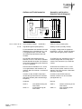
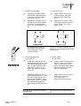
riese electronic gmbh Junghansstraße 16 D-72160 Horb a. N. Tel. +49-(0)7451-55010 Fax. +49-(0)7451-550170 http://www.riese-electronic.de 13 23 33 A1 Y1 Y2 Original Betriebsanleitung für Sicherheitsrelais SAFE 1/SAFE 1.1 riese Safe 1 13 23 14 24 Zielgruppe/ Target audience 33 34 41 Power Channel 2 Channel 42 1 41 42 A2 14 24 34 Original operating Instructions for emergency relay and safety gate monitoring relay SAFE 1/SAFE 1.1 Einleitung Introduction Diese Betriebsanleitung soll Sie mit dem Not-Halt Sicherheitsrelais und Schutztürwächter SAFE 1 / SAFE 1.1 vertraut machen. Die Betriebsanleitung richtet sich an folgende Personen: This operating instruction should make you familiar with the emergency stop and safety gate monitoring relays SAFE 1 / SAFE 1.1 Qualified professionals who plan and develop safety equipment for machines and plants and who are familiar with the safety instructions and safety regulations. Qualified professionals, who install safety equipment into machines and plants and put them into operation. Qualifizierte Fachkräfte, die Sicherheitseinrichtungen für Maschinen und Anlagen planen und entwickeln und mit den Vorschriften über Arbeitssicherheit und Unfallverhütung vertraut sind. Qualifizierte Fachkräfte, die Sicherheitseinrichtungen in Maschinen und Anlagen einbauen und in Betrieb nehmen. The operating instruction is addressed to the following persons: In dieser Betriebsanleitung werden einige Symbole verwendet, um wichtige Informationen hervorzuheben: The operating instruction contains several symbols which are used to high-light important information: Dieses Symbol steht vor Textstellen, die unbedingt zu beachten sind. Nichtbeachtung führt zur Verletzung von Personen oder zu Sachbeschädigung This symbol is placed in front of text which has to be absolutely paid attention to. Nonobservance leads to serious injuries or damage to property. Dieses Symbol kennzeichnet Textstellen, die wichtige Informationen enthalten. This symbol is placed in front of text, which contains important information. ) Dieses Zeichen kennzeichnet auszuführende Tätigkeiten This sign is placed in front of activities ⇒ Nach diesem Zeichen wird beschrieben, wie sich der Zustand nach einer ausgeführten Tätigkeit ändert. After this sign follows a description on how the situation has changed after an activity is performed. © Copyright Alle Rechte vorbehalten. Änderungen, die dem technischen Fortschritt dienen, vorbehalten. © Copyright All rights reserved. Changes, which serve technical improvements are reserved. Zeichenerklärung/ Explanation of signs ! SAFE 1 / SAFE 1.1 160813 1/9 Bestimmungsgemäße Verwendung Sicherheitshinweise Safety indications Das Sicherheitsrelais SAFE 1 / SAFE 1.1 sind bestimmt für den Einsatz in: The safety relay SAFE 1 / SAFE 1.1 can be used for: Application: ! Single-or dual channel capability for emergency stop. Single-or dual channel capability with limit switches for safety gates. Person and object – protection aren’t guarantee, if the safety relay isn’t use by adequate define application. Beachten Sie unbedingt die folgenden Punkte: Please note the following points: Zu Ihrer Sicherheit For your safety SAFE 1 / SAFE 1.1 160813 Personen - und Sachschutz sind nicht mehr gewährleistet, wenn das Sicherheitsrelais nicht entsprechend seiner bestimmungsgemäßen Verwendung eingesetzt wird. ! Ein-oder zweikanalige Schaltungstechnik für Not-Halt-Schalter Ein-oder zweikanalige Schaltungstechnik mit Grenztaster für Schiebeschutzgitter. Das Gerät darf nur unter Beachtung dieser Betriebsanleitung von Fachpersonal installiert und in Betrieb genommen werden, das mit den geltenden Vorschriften über Arbeitssicherheit und Unfallverhütung vertraut ist. Elektrische Arbeiten dürfen nur von Elektrofachkräften durchgeführt werden. Beachten Sie die jeweils gültigen Vorschriften, insbesondere hinsichtlich der Schutzmaßnahmen. Reparaturen, insbesondere das Öffnen des Gehäuses, dürfen nur vom Hersteller oder einer von ihm beauftragten Person vorgenommen werden. Ansonsten erlischt jegliche Gewährleistung. Vermeiden Sie mechanische Erschütterungen beim Transport oder im Betrieb; Stöße größer 5g/33Hz können zur Beschädigung des Gerätes führen. Montieren Sie das Gerät in einem staub- und feuchtigkeitsgeschütztem Gehäuse; Staub und Feuchtigkeit kann zu Funktionsstörungen führen. Sorgen Sie für eine ausreichende Schutzbeschaltung bei kapazitiven und induktiven Lasten an den Ausgangskontakten. The unit should only be installed and operated by persons, who are familiar with both these instructions and the current regulations for safety at work and accident prevention. Follow local regulations as regards preventative measures. Any guarantee is void following opening of the housing or unauthorized modifications. Avoid mechanical vibrations greater than 5 g / 33 Hz when transporting and in operation. The unit should be panel mounted in an enclosure rated at IP 54 or better, otherwise dampness or just could lead to function impairment. Adequate fuse protection must be provided on all output contacts with capacitive and inductive loads. 2/9 Aufbau und Funktionsweise A1 A2 (+) (-) Assembly and function (function circuit diagram) Y1 Y2 13 23 33 41 14 24 34 42 elektr. Sicherung / electr. fuse K1 ~ ~ Überwachungslogik / control logic ~ ~ = K2 + K1 K2 Ausgangskontakte: 13-14, 23-24, 33-34 41-42 Sicherheitsstrompfade (Schließer) safety circuits (normally open) Signalisierungsstrompfad (Öffner) auxiliary circuits (normally closed) Für das Betreiben des Gerätes muß eine Hilfsspannung an die Klemmen A 1 und A 2 angelegt werden. Die LED `Netz` leuchtet bei geschlossenem Not-HaltSchalter. An supply voltage must be applied at terminals A 1 and A 2. Power LED illuminates if the emergency stop is closed. Zum START des Gerätes muß die Klemme Y2 mit Y1 über einen Schließerkontakt überbrückt werden. Die Funktion wird bei der Überbrückung der Klemmen Y2 und Y1 gestartet. To START the unit, terminals Y2 and Y1 must be bridged with a normally open contact. The unit works if you close this contact. Danach sind die Kontakte 13-14, 23-24, 33-34 geschlossen, der Kontakt 41-42 geöffnet. Die LED´s Kanal 1 und Kanal 2 leuchten. At this time the contacts 13-14, 23-24 and 33-34 are closed, contact 41-42 is opened. The LED’s channel 1 illuminate, channel 2 illuminate. In Reihe zu dem START-Taster kann die Schaltung eines externen Schützes überwacht werden (siehe Anwendungsbeispiel 2) In series to this START-button an external contactor can be controlled (see application 2). Varianten: Devices: SAFE 1: SAFE 1.1: SAFE 1 / SAFE 1.1 160813 Output contacts: ohne Überwachung der Start-Taste mit Überwachung der Start-Taste SAFE 1: SAFE 1.1: without monitoring of the start bottom with monitoring of the start bottom 3/9 Elektrischer Anschluß Electronic connection 13 23 A1 Mounting and opening Für eine sichere Funktion muß das Sicherheitsrelais in ein staub- und feuchtigkeitsgeschütztes Gehäuse eingebaut werden (IP54). The unit should be panel mounted in an enclosure rated at IP 54 or better, otherwise dampness or dust could lead to function impairment. ) ) Montieren Sie das Sicherheitsrelais auf eine Normschiene Führen Sie die Verdrahtung entsprechend des Verwendungszweckes durch. Orientieren Sie sich dabei an den Anwendungsbeispielen. Generell ist das Sicherheitsrelais nach folgenden Angaben zu verdrahten: Carry out the wire appropriate the use. According to the examples of application. General the safety-relay has to be wire under following specifications: 1. Aktivierungs- und Rückführungskreis schließen 1. Close the feedback control loop and the activation circuit ) ) Automatische Aktivierung: Y2 – Y1 brücken oder externe Schütze schließen. 33 Bedingte Aktivierung: Taster an Y2 – Y1 anschließen (keine Brücke an Y2 – Y1). Externe Schütze werden in Reihe zum START-Taster an die Klemmen Y2 –Y1 angeschlossen. Y1 Y2 riese Safe 1 13 23 33 14 24 34 42 41 Power Channel 2 Channel 1 41 42 A2 14 24 34 There is a notch on the rear of the unit for DIN-Rail attachment. Automatic activation: bridge Y2 – Y1 or close N.C. contacts of external contactors. Conditional activation: Connect button on Y2 – Y1 (no bridge on Y2 – Y1). N.C. contacts of external contactors are wired in series with the STARTbutton at the terminals Y2 – Y1. Start Start Y2 Y2 Y2 Y1 Y1 Automatische Aktivierung / automatic activation SAFE 1 / SAFE 1.1 160813 Y1 K2 ext mechanical mounting Montage und Inbetriebnahme K1 ext Mechanische Montage Start über Start-Taste / start over start-button Start über Start-Taste und Anschluß Maschinenfreigabekreise / Schützkontrolle start over start-button and connection maschine-release-circle 4/9 2. Eingangskreis schließen 2. Close input circuit ) ) ) Einkanalig: Schließen sie den Kontakt des Auslöseelementes an positive Versorgungsspannung und A1 (+) an Zweikanalig: Schließen sie die Kontakte des Auslöseelementes an positive Versorgungsspannung - A1 (+) und Masse - A1 (-) an. ) Singel-channel: Connect contacts from trigger element to positive supply voltage and A1 (+). Dual-channel: connect contact from trigger element to positive supply voltage – A1 (+) and earth – A1(-). 24 VAC/DC 24 VAC/DC Auslöseelement trigger element Auslöseelement trigger element A1 (+) A2 (-) A1 (+) zweikanalig / dual channel einkanalig / single-channel 13 23 A1 Die Verdrahtung der Versorgungsspannung ist abhängig vom Gerätetyp (s. Typenschild am Gerät). 33 A2 (-) The wire of the supply voltage is dependent on device-model (see type plate on the device). Y1 Y2 riese Safe 1 13 23 33 14 24 34 41 42 Power Channel 2 Channel 1 41 42 A2 14 24 34 3. Versorgungsspannung Uv 24V AC/DC 3. Supply voltage Uv 24V AC/DC ) ) ! 4. Einkanalig: Schließen Sie die Versorgungsspannung Uv + UvN über den Kontakt des Not-Halt bzw. Schutztürschalters an die Klemmen A1 und U v -UvN (Null-Leiter) direkt an die Klemme A2 an. Zweikanalig: Schließen Sie die Versorgungsspannung Uv + UvN über den Kontakt des Not-Halt bzw. Schutztürschalters an die Klemmen A1 und U v - UvN über den zweiten Kontakt des NotHalt-Schalters an die Klemme A2 an. Beachten Sie unbedingt die maximalen Leitungslängen. SAFE 1 / SAFE 1.1 160813 4. Single-channel: The Supply voltage Uv + has to be connected over the contact from emergency stop / safety gate monitoring to the terminal A1 and Uv directly to terminal A2 Dual-channel: over the second contact from emergency stop / safety gate Monitoring to the terminal A2. Please note the max. lengths of the cables. 5/9 Wartung und Reparatur Maintenance and repair Das Sicherheitsrelais arbeitet wartungsfrei. The safety – relay function maintenancefree. Zum Austausch des Gerätes empfehlen wir die Kabel 1 zu 1 abzuschrauben und an das Austauschgerät anzuschrauben. 1. Kabel abschrauben und an dem Austauschgerät anschrauben. 2. Defektes Gerät von der Hutschiene nehmen. 3. Austauschgerät auf Hutschiene montieren. For exchange of the device, we advise to screw off the terminals1 to 1 and to screw on the exchange-device. 1. You must screw off the cable and screw on the exchange - device. 2. Take away the defective device from the DIN - Rail. 3. Mount the new device on the DIN - Rail. 1. 1. 2. 3. Fehler/Störungen, Auswirkung und Maßnahmen Faults, effect and measures Erdschluß bei AC - DC-Variante (mit elektr. Sicherung) / Earth fault AC / DC-version (with electronic fuse protection) Die Sicherung löst aus. Die Ausgangskontakte öffnen. Nach Wegfall der Störursache und Einhalten der Betriebs-spannung ist das Gerät wieder betriebsbereit. An electronic fuse release the output contacts to open. Once the reason of the disturbance is removed and the rated voltage is observed, the device is ready for operation. Fehlfunktion der Kontakte / Faulty contact functions Bei verschweißten Kontakten ist nach Öffnen des Ausgangskreises keine neue Aktivierung möglich. In the case of welded contacts, further activation is not possible following an opening of the input circuit. Nur eine oder keine LED brennt / Only one or no LED illuminates Externer Beschaltungsfehler oder interner Fehler. Externe Beschaltung prüfen. Wenn Fehler immer noch vorhanden, Gerät an riese electronic einschicken. External wiring or internal fault is present. Test the external wiring. When the flaw is still available, send the device to riese electronic. SAFE 1 / SAFE 1.1 160813 6/9 Technische Daten / Technical Data Elektrische Daten / electrical data Versorgungsspannung Uv / supply voltage Spannungsbereich / voltage range Frequenz (AC-Variante) / frequency (AC-type) Leistungsaufnahme ca. / power consumption appr. Leitungsdaten / conductor data Leiteranschluß / conductor connection Max. Leitungslängen (Eingangskreis) / max. conductor length (input circuit) Leiterquerschnitt / conductor cross-section Kapazität / capacity Widerstand / resistance Temperatur / temperature Max. Länge / max. length Kontaktdaten 24V AC/DC 0,90 ...1,1 UB 50 ... 60 Hz ca. 2,5 VA / 2,5 W 2 x 1,5 mm2 Massivdraht (Cu) / massive wire 2 2 x 1,5 mm Litze (Cu) mit Hülse / strand with hull DIN VDE 46228 Use 60/75°C copper wire only! 2 x 1,5 mm2 150 nF/km 11,7 Ohm /km + 25°C 2 x 0,5 km (einkanalig / single channel) 4 x 0,5 km (zweikanalig / dual channel) / contact data Kontaktbestückung / contact-allocation Kontaktart / contact type Kontaktmaterial / contact material Schaltspannung / switching voltage Schaltstrom / switching current Max. Schaltvermögen / max. switching capability DIN EN 60947-5-1 Schaltleistung max. / max. switching capacity Mechanische Lenbensdauer / mechanical lifetime 3 Schließer / 1 Öffner 3 normally safety open / 1 auxiliary closed Relais zwangsgeführt / relay positive guided AgSnO2 oder vergleichbares Material / AgSnO2 or comparable material 250V AC, 24V DC 5A AC 14 230 V / 5,0 A DC 13 24 V / 5,0 A 1250 VA (ohmsche Last) / 1250 VA (ohm load) 107 Schaltspiele / switches Kriech- und Luftstrecken -DIN VDE 0160 / creeping distance and clearance Kontaktabsicherung / contact security für Verschmutzungsgrad 2, Überspannungskategorie 2 / 250 V DIN VDE 0160 at pollution grade 2, over voltage category 2 / 250 V -Basisisolierung: Überspannungskategorie 3 / 250 V basis isolation: over voltage category 3 / 250 V 6,3 A flink oder 4 A träge DIN VDE 0660 Teil 200 6,3 A brisk or 4 A inert DIN VDE 0660 part 200 < 100 ms * Rückfallverzögerung K1/delay on deenergisation K1 Wiederbereitschaftszeit (minimale Abschaltzeit der Eingänge) / restarting readines time (minimum switch off time the inputs) 0,5 s Mechanische Daten / mechanical data Gehäusematerial / housing material Abmessungen (BxHxT) in mm / dimensions ( bxhxd ) Befestigung / fastening Max. Anzugsdrehmoment / max. tighening torque Gewicht mit Klemmen Lagerung / weight with terminals / storage Umgebungsdaten / environmental data Umgebungstemperatur / Luftfeuchte / Schutzart Klemmen / Schutzart Gehäuse / Stoßfestigkeit / operating temperature humidity terminal type housing type shock resistance Noryl SE 100 22,5 x 80 x 99 Schnappbefestigung für Normschiene / click-fastening for DIN-Rail 0,4 Nm (Tighten to 1 N.m. Overtorquing may cause enclosure breakage.) Max. 185g In trockenen Räumen / in dry areas -25°C ... +55°C IP 20 DIN VDE 0470 Teil 1 / part 1 IP 40 DIN VDE 0470 5g, 33 Hz VDE 0160 Zertifizierungen / certifications Geprüft nach / tested in accordance with Erreichtes Level/Kategorie / achieved level/category MTTFd [Jahre] / MTTFd [years] DC CCF EN ISO 13849-1 Performance Level d , Kat.3 37,57 “hoch/high” 90% “mittel/medium” erfüllt/achieved * korrigiert bei Umstellung auf ROHS-konforme Ausführung SAFE 1 / SAFE 1.1 160813 7/9 Anwendungsbeispiele Examples for applications Beispiel 1: Einkanalige Not-Halt-Schaltung. 24V AC/DC NotHalt/ ESTOP START Y2 A1(+) A2(-) Y1 33 23 13 41 bis Kategorie 2; SIL1; PLd erreichbar up to category 2; SIL1; PLd reachable U ext. S ext. K1ext. K2 ext. 24V AC/DC START Y2 NotHalt/ ESTOP A1(+) A2(-) Y1 13 23 33 41 14 K2 ext. K1ext. Example 1: Single-channel emergency stop. Mit dem START-Taster wird das Gerät aktiviert. Die Kontakte 13-14, 23-24, 3334 schließen und der Kontakt 41-42 öffnet. Über den AUS-Taster oder Not-Halt fallen die Kontakte in ihre Grundstellung zurück. Pressing the START-button, the unit will be activated. Contacts 13-14, 23-24 and 33-34 are closed, contact 41-42 opens. Pressing the emergency stop will reset the contacts. Beispiel 2: Einkanalige Not-HaltSchaltung mit externer Kontakterweiterung (2 Schütze) und Kontaktüberwachung. Example 2: Single-channel emergency stop with external contact extension (2 contactors) and contact monitoring. In diesem Beispiel werden 2 externe Schütze mit Kontaktzwangsführung verwendet. Je ein Öffnerkontakt dieser beiden Schütze muß in Reihe zum STARTTaster angeschlossen werden. Über einen Schalter S ext. können die externen Schütze zu einem beliebigen Zeitpunkt dazugeschaltet bzw. abgeschaltet werden, wenn das SAFE 1... aktiviert ist. In this application uses two external positive guided contactors. One normally closed contact of each contactor must be connected in series to the START-button. Through the switch S ext. the external contactors can be operated or turned off at any time the SAFE 1... is activated. . bis Kategorie 2; SIL1; PLd erreichbar up to category 2; SIL1; PLd reachable Beispiel 3: Einkanalige Schutztürüberwachung 24V AC/DC START S1 Y2 Y1 A1(+) A2(-) 13 23 33 bis Kategorie 2; SIL1; PLd erreichbar up to category 2; SIL1; PLd reachable 41 Wird der Schutztürtaster S 1 geschlossen, bleiben die Ausgangskontakte unverändert. Erst mit der START-Taste wird das Gerät aktiviert. Die Kontakte 13-14, 23-24 und 33-34 schließen. Beim Öffnen des Schutztürtasters fallen die Kontakte unverzögert in ihre Grundstellung zurück. Mittels einer Brücke zwischen Y2-Y1 ist eine automatische Aktivierung möglich. Diese Funktion ist nur mit der Gerätevariante SAFE 1 möglich. Example 3: Single-channel gate monitoring If the button S1 of the gate is closed the output contacts do not change. Pressing the START-button activates the SAFE 1.. The contacts 13-14,23-24 and 33-34 are closed. Opening S1 of the safety gate the outputs open immediately. By bridging the START-button terminals Y1 and Y2 the relay will start automatically and reset automatically. Automatic start and reset start is only possible using the SAFE 1 version. Ergänzender Hinweis Additional advice ! SAFE 1 / SAFE 1.1 160813 Bei entsprechender Verdrahtung nach Applikationsbeispielen 1 bis 3 muss durch den Anwender eine Anbindung an die Maschinensteuerung für die zyklische Testung erfolgen. With wiring according to application examples 1 to 3 the user must provide a connection to the machine control for cyclic testing. 8/9 24V AC/DC NotHalt/ ESTOP START Y2 A1(+) A2(-) Y1 13 23 33 41 bis Kategorie 3; SIL2; PLd erreichbar up to category 3; SIL2; PLd (mit getrennten Mantelleitungen) 24V AC/DC START S1 Y2 Y1 S2 A1(+) A2(-) 13 23 33 bis Kategorie 3; SIL2; PLd erreichbar up to category 3; SIL2; PLd reachable (mit getrennten Mantelleitungen) SAFE 1 / SAFE 1.1 160813 41 Beispiel 4: Zweikanalige Not-HaltSchaltung. Example 4: Dual-channel emergency stop. Bei der zweikanaligen Not-HaltSchaltung werden die Öffnerkontakte des Not-Halt-Schalters in Reihe zur Spannungsversorgung geschalten. Mit dem START-Taster wird das Gerät aktiviert. Die Kontakte 13-14, 23-24 und 3334 schließen, der Kontakt 41-42 öffnet. Über den Not-Halt-Schalter fallen die Kontakte in ihre Grundstellung zurück. For this application the normally closed contacts of the emergency STOP-button must be connected in series to the power supply. With the START-button the unit is started. The contacts 13-14, 23-24 and 33-34 are closed, contact 41-42 opens. Pressing the emergency stop will rest the contacts. Beispiel 5: Zweikanalige Schutztürüberwachung. Example 5: Dual-channel safety gate monitoring. Werden die Schutztürtaster geschlossen, bleiben die Ausgangskontakte unverändert. Erst mit der START-Taste wird das Gerät aktiviert. Die Kontakte 13-14, 2324 und 33-34, der Kontakt 41-42 öffnet. Beim Öffnen der Schutztürtaster fallen die Kontakte unverzögert in ihre Grundstellung zurück. Mittels einer Brücke zwischen Y2-Y1 ist eine automatische Aktivierung möglich. Diese Funktion ist nur mit der Gerätevariante SAFE 1 möglich. If the safety gate switches S1 and S2 are closed, the output contacts remain unchanged. The device will be activated with the START-button. Contacts 13-14, 23-24 and 33-34 closed, contact 41-42 opens. Opening the safety gate switches return the contacts immediately to their normal position. By bridging the STARTbutton terminals Y2 and Y1 the relay will start automatically and reset automatically. Automatic start and automatic reset is only possible using the SAFE 1 version. 9/9 Stammhaus Niederlassung Ost riese electronic gmbh Junghansstr. 16 72160 Horb am Neckar Telefon +49 (0) 74 51 55 01 0 Telefax +49 (0) 74 51 55 01 70 [email protected] www.automation-safety.de Industrievertretung für Automation und Sicherheit Dr.-Riese-Str. 1 07937 Langenwolschendorf Telefon +49 (0) 3 66 28 7 25 0 Telefax +49 (0) 3 66 28 7 25 17 [email protected] www.automation-safety.de PLZ 0 Vertreter Distributor Distributor Distributor Distributor riese electronic gmbh Hagemeyer Deutschland GmbH&Co.KG Unielektro Fachgroßhandel GmbH&Co. KG Behrendt GmbH Bublitz u. Profe GmbH Niederlassung Ost Dr.-Riese-Str. 1 07937 Langenwolschendorf Telefon +49 (0) 3 66 28 7 25 0 Telefax +49 (0) 3 66 28 7 25 17 [email protected] www.automation-safety.de Dammweg 15 01454 Radeberg / Dresden Telefon +49 (0) 35 28 43 30 Telefax +49 (0) 35 28 43 32 60 5 [email protected] www.hagemeyerce.com Kauffahrtei 17 09120 Chemnitz Telefon +49(0)371 53072-0 Telefax +49(0)371 53072-50 [email protected] www.unielektro.de Elektro-Großhandel August-Bebel-Str. 21 03046 Cottbus Telefon +49 (0) 35 53 81 68 0 Telefax +49 (0) 35 57 94 08 4 [email protected] www.behrendt-elektrogrosshandel.de Elektrogroßhandlung Lauenhainer Weg 4 08393 Meerane Telefon +49 (0) 37 64 40 10 0 Telefax +49 (0) 37 64 40 10 44 [email protected] www.bublitz-profe.de Distributor Distributor Vertreter PLZ 1 Vertreter PLZ 2 PLZ-Gebiet: 10000-19417 PLZ-Gebiet: 29000-29999 Distributor Schumer Ingenieurgesellschaft GmbH ime Elektrotechnik GmbH Berlin Ingenieurbüro Korinek Harzer Antriebstechnik GmbH Rolf Zabel Rückertstr. 4 04157 Leipzig Telefon +49 (0) 3 41 9 12 95 11 Telefax +49 (0) 3 41 9 12 95 39 [email protected] www.schumer.de Beusselstrasse 44 n-q 10553 Berlin - Tiergarten Telefon +49 (0) 30 302086-0 Telefax +49 (0) 30 390 390 65 [email protected] www.ime.eu Gleyewg 76 10318 Berlin-Karlshorst Telefon +49 (0) 30 Telefax +49 (0) 30 [email protected] www.korinek.de Dolomitstr. 7 37431 Bad Lauterberg / Harz Telefon +49 (0) 55 24 92 28 0 Telefax +49 (0) 55 24 92 28 70 [email protected] www.antreiben.de Fahrener Weg 59b 27777 Ganderkesee Telefon +49 (0) 42 22 94 69 80 Telefax +49 (0) 42 22 79 40 48 [email protected] www.dieselzab.de Vertreter PLZ-Gebiet: 30000-31999/ Distributor 34000-34999/37000-38999 PLZ 3 Vertreter PLZ-Gebiet: 39000-39649 Rückertstr. 4 04157 Leipzig Telefon +49 (0) 3 41 9 12 95 11 Telefax +49 (0) 3 41 9 12 95 39 [email protected] www.schumer.de Distributor Hagemeyer Deutschland GmbH&Co.KG Hagemeyer Deutschland GmbH&Co.KG Elektrofachgroßhandel GmbH Beiersdorfstr. 7 30165 Hannover Telefon +49 (0) 51 16 30 12 86 Telefax +49 (0) 51 16 30 12 95 www.rexel.de / [email protected] In den Giesen 21 36251 Bad Hersfeld Telefon +49 (0) 66 21 16 00 Telefax +49 (0) 66 21 16 01 00 [email protected] www.hagemeyerce.com Robert-Bosch-Straße 1c 38112 Braunschweig Telefon +49 (0) 53 1 31 90 20 Telefax +49 (0) 53 13 19 02 99 [email protected] www.hagemeyerce.com Distributor Distributor Distributor PLZ 3 Distributor Distributor Rexel Deutschland Harzer Antriebstechnik GmbH Dolomitstr. 7, 37431 Bad Lauterberg / Harz Telefon +49 (0) 55 24 92 28 0 Telefax +49 (0) 55 24 92 28 70 [email protected] www.antreiben.de Schumer Ingenieurgesellschaft GmbH PLZ 4 Distributor Eltplan Vertriebs GmbH Klömich Elektrotechnik u. Vertrieb WAGNER GMBH GSS Industrie-Electronic GmbH RMI-Automation GmbH Bohmter Str. 18 49152 Bad Essen Telefon +49 (0) 54 72 94 15 0 Telefax +49 (0) 54 72 94 12 56 [email protected] www.eltplan-bad-essen.de Habichtsbornstraße 3 34355 Staufenberg Telefon +49 (0) 5543 302588 Telefax +49 (0) 5543 302589 [email protected] www.klömich.de Robert-Bosch-Str. 35 42489 Wülfrath Telefon +49 (0) 2058 782800-0 Telefax +49 (0) 2058 782800-49 [email protected] www.wagnergmbh.de Wallgraben 18 48356 Nordwalde Telefon +49 (0) 25 73 93 84 0 Telefax +49 (0) 25 73 93 84 29 [email protected] www.gss-industrie-electronic.de Jacksonring 30 48429 Rheine Telefon +49 (0) 59 71 98 04 50 Telefax +49 (0) 59 71 98 04 52 8 [email protected] www.rmi-automation.de PLZ 4 PLZ 5 Distributor Distributor Distributor Distributor Eltplan Vertriebs GmbH ETL Paul Schlegel GmbH WAGNER GMBH Eltplan Vertriebs GmbH Mühlenbeck Bohmter Str. 18 49152 Bad Essen Telefon +49 (0) 54 72 94 15 0 Telefax +49 (0) 54 72 94 12 56 [email protected] www.eltplan-bad-essen.de Weyerstraßer Weg 161 50969 Köln Telefon +49 (0) 22 1 93 64 60 0 Telefax +49 (0) 22 1 93 64 60 99 [email protected] www.schlegel-gruppe.de Robert-Bosch-Str. 35 42489 Wülfrath Telefon +49 (0) 2058 782800-0 Telefax +49 (0) 2058 782800-49 [email protected] www.wagnergmbh.de Bohmter Str. 18 49152 Bad Essen Telefon +49 (0) 54 72 94 15 0 Telefax +49 (0) 54 72 94 12 56 [email protected] www.eltplan-bad-essen.de Industrievertretungen CDH Herminghausen 3 58256 Ennepetal Telefon +49 (0) 23 33 60 86 20 Telefax +49 (0) 23 33 60 86 21 [email protected] www.muehlenbeck-info.de PLZ 5 PLZ 6 PLZ 7 Distributor Distributor Distributor Sonepar Deutschland Region West GmbH Natroper Str. 9 59439 Holzwickede Telefon +49 (0) 23 01 8 10 Telefax +49 (0) 23 01 44 77 [email protected] www.sonepar.de Distributor Franz K. Appel e.K. ELVA Industrielle Automatisierungs GmbH CEF Elektrofachgrosshandlung Gimmeldinger Str. 62a 67433 Neustadt/Weinstraße Telefon +49 (0) 63 21 33 81 4 Telefax +49 (0) 63 21 34 65 7 [email protected] www.entrelec.de Reinerstraße 26 74080 Heilbronn Telefon +49 (0) 71 31 91 29 0 Telefax +49 (0) 71 31 91 29 29 [email protected] www.elva-automation.de Südwest GmbH / Gruppenbüro Karlsruhe Ottostr. 2 76227 Karlsruhe Telefon +49 (0) 62 1 72 89 20 Telefax +49 (0) 62 1 72 27 45 [email protected] Distributor Distributor EGV-Fritz GmbH + Co.KG Zazenhäuser Straße 70 70437 Stuttgart-Zuffenhausen Telefon +49 (0) 711 820517-0 Telefax +49 (0) 711 820517-77 [email protected] www.egv-fritz.de PLZ 8 PLZ 9 Distributor Distributor Distributor Hagemeyer Deutschland GmbH&Co.KG Lucom GmbH FEGA & Schmitt Hagemeyer Deutschland GmbH&Co.KG riese electronic gmbh /Niederlassung Ost Ansbacher Str. 2a 90513 Zirndorf Telefon +49 (0) 91 27 59 46 00 Telefax +49 (0) 91 27 59 46 20 [email protected] www.lucom.de Elektrogrosshandel GmbH Rettistr. 5 91522 Ansbach Telefon +49 (0) 98 18 90 30 Telefax +49 (0) 98 18 90 31 74 www.fega-schmitt.de Lochweg 15 97318 Kitzingen Telefon +49 (0) 93 21 93 77 0 Telefax +49 (0) 93 21 93 77 51 [email protected] www.hagemeyerce.com Dr.-Riese-Str. 1, 07937 Langenwolschendorf Telefon +49 (0) 3 66 28 7 25 0 Telefax +49 (0) 3 66 28 7 25 17 [email protected] www.automation-safety.de Distributor Distributor Vertreter Ridlerstraße 71 80339 München Telefon +49 (0) 89 50 06 60 Telefax +49 (0) 89 50 06 66 45 [email protected] www.hagemeyerce.com Distributor Ausland Belgien Vertreter Frankreich Koning & Hartmann B.V. Laumans BVBA Rotero Belgium BVBA DISIMPEX Woluwelaan 31 B-1800 Vilvoorde Telefon +32 22 57 02 40 Fax +32 22 57 02 49 [email protected] www.koningenhartmann.com Weertersteenweg 138/2 B-3640 Kinrooi Telefon +32 89 70 20 96 Fax +32 89 70 20 97 [email protected] www.laumans.com Wayenborgstraar 10 B-2800 Mechelen Telefon +32 15 45 18 40 Fax + 32 15 45 18 41 [email protected] www.rotero.be 14 rue Joseph Graff F-67810 Holzheim Telefon +03 90 20 74 20 Fax +03 88 76 90 83 [email protected] www.disimpex.com Niederlande Distributor Distributor Distributor Laumans Techniek B.V.: Rotero B.V. Isotron Systems B.V. Fahrenheitstraat 12 NL-6003 DC Weert Telefon +31 49 55 21 06 7 Fax +31 49 55 42 45 7 [email protected] www.laumans.com Postbus 126 NL-3440 AC Woerden Telefon +31 34 84 95 15 0 Fax +31 34 84 95 17 1 [email protected] www.rotero.com Afrikalaan 21-23 NL-5232 BD 's-Hertogenbosch Telefon +31 73 63 91 63 9 Fax +31 73 63 91 69 9 [email protected] www.isotron.nl Distributor Distributor Schweiz Vertreter Österreich Bachofen AG Surber AG Reliste Steuerungstechnik GesmbH Industrielle Automation/Abt.Schalttechnik Ackerstraße 42 / CH-8610 Uster Telefon +41 (0) 44 944 11 11 Fax +41 (0) 44 944 10 04 [email protected] www.bachofen.ch Industriestr. 7 CH-4653 Obergösgen Telefon +41 62 29 50 33 3 Fax +41 62 29 50 30 2 [email protected] www.surberag.ch Vertriebsleitung Enzersdorfer Str. 8-10 A-2345 Brunn am Gebirge Telefon +43 22 36 31 52 50 Fax +43 22 36 31 52 56 0 [email protected] Überreicht durch: Vertreter PLZ-Gebiet: 98/99