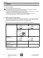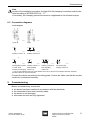
1
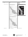
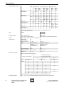
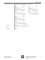
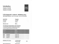
Operating Instructions Residual current circuit-breaker with integral overcurrent protection > 8562/5 Contents 1 Contents 1 2 3 4 5 6 7 8 9 10 11 12 13 2 Contents ................................................................................................................2 General Information ...............................................................................................2 Safety Instructions .................................................................................................3 Conformity to Standards ........................................................................................3 Function .................................................................................................................3 Technical Data ......................................................................................................4 Arrangement and Assembly ..................................................................................8 Installation ...........................................................................................................10 Commissioning ....................................................................................................11 Maintenance ........................................................................................................11 Transport and Storage ........................................................................................12 Disposal ...............................................................................................................12 EC Declaration of Conformity ..............................................................................13 General Information 2.1 Manufacturer R. STAHL Schaltgeräte GmbH Am Bahnhof 30 74638 Waldenburg Germany Tel: Fax: Internet: +49 7942 943-0 +49 7942 943-4333 www.stahl-ex.com 2.2 Operating Instructions Information ID-No.: Publication Code: 149915 / 8562606300 2014-06-04·BA00·III·en·08 Subject to alterations. 2.3 Symbols Warning! This symbol indicates advice which, if ignored, puts your health or the ability of the device or components to function at risk. Note This symbol indicates important additional information, tips and recommendations. 2 Residual current circuit-breaker with integral overcurrent protection 8562/5 149915 / 8562606300 2014-06-04·BA00·III·en·08 Safety Instructions 3 Safety Instructions The most important safety instructions are summarized in this section. They supplement the corresponding regulations which the staff responsible must study. When working in areas, subject to explosion hazards, the safety of personnel and plant depends on complying with all relevant safety regulations. Assembly and maintenance staff working on installations therefore have a particular responsibility. They require precise knowledge of the applicable standards and regulations. As a user, please observe: national safety and accident prevention regulations, national assembly and installation regulations (e.g. IEC/EN 60079-14), generally recognised technical regulations, safety instructions and information in these operating instructions, characteristic values and rated operating conditions on the rating and data plates, instruction plates on the unit, that any damage can invalidate the Ex-protection. Use the devices in accordance with their designated use and for their intended purpose only (see “Function“ on page 3). Incorrect or impermissible use or non-compliance with these instructions invalidates our warranty provision. No modifications or alterations to the devices impairing their explosion protection are permitted. The devices must only be fitted and operated if they are undamaged, dry and clean. 4 Conformity to Standards Conformity with standards and regulations is specified in the corresponding certificates and declarations of the manufacturer (e.g. EC Declaration of Conformity). These documents are available for download in the download area on the internet page www.stahl-ex.com. The devices are approved for use in hazardous areas of Zones 1 and 2. 5 Function The series 8562 residual current circuit-breaker with overcurrent protection is used in hazardous areas and protects cables against overload and short-circuit, and also personnel by limiting the duration of residual currents by switching off. It is designed for fitting into an enclosure with type of protection “Increased safety e“. 149915 / 8562606300 2014-06-04·BA00·III·en·08 Residual current circuit-breaker with integral overcurrent protection 8562/5 3 Technical Data 6 Technical Data Type 8562/5 8562/54-246.-... 8562/54-247.-... 8562/54-248.-... ATEX E II 2 G Ex d e IIC Gb E I M 2 Ex d e I Mb E II 2 G Ex d e IIC Gb E I M 2 Ex d e I Mb IECEx Ex d e IIC Ex d e I Ex d e IIC Ex d e I ATEX PTB 02 ATEX 1049 U PTB 02 ATEX 1049 U IECEx IECEx PTB 06.0062U IECEx PTB 06.0062U Rated insulation voltage 500 V 500 V No. of poles 1 pole + N; 2 pole 2 pole Rated operational voltage 127 ... 230 V AC 133 ... 230 V AC 125 V DC with 2 contact strips connected in series Minimal voltage Ubmin 1-pole + N: 100 V AC 2-pole: 127 V AC Explosion protection Gas explosion protection Certificates Electrical data 2-pole: 12 V AC; 12 V DC Maximal voltage Ubmax 250 V AC; 53 / 120 V DC 253 V AC Rated working and leakage currents IN = 6 ... 40 A; IΔN = 10 / 30 / 100 / 300 mA IN = 6 ... 40 A; IΔN = 10 / 30 / 100 / 300 mA Tripping time at rated residual current 1 x 1.4 IΔN ( 300 ms 5 x 1.4 IΔN ( 40 ms 1 x 1.4 IΔN ( 300 ms 5 x 1.4 IΔN ( 40 ms Working area of the control unit 180 ... 255 V 180 ... 255 V Rated frequency 50 ... 60 Hz 50 ... 60 Hz Impact strength 250 A, 8 / 20 ms 250 A, 8 / 20 ms Mechanical 2x10⁴ switching cycles 2x10⁴ switching cycles Electrical 104 switching cycles 104 switching cycles Service life 4 Utilization category A (acc. to IEC/EN 60947-2) A (acc. to IEC/EN 60947-2) Isolation function yes (IEC/EN 60947-2) yes (IEC/EN 60947-2; IEC/EN 60898-1; EN/DIN 60664-1) Pulse resistance 6 kV ( 6,2 kV Residual current circuit-breaker with integral overcurrent protection 8562/5 149915 / 8562606300 2014-06-04·BA00·III·en·08 Technical Data Type 8562/54-246.-... 8562/54-247.-... 8562/54-248.-... 8562/5 Tripping characteristic curves Tripping characteristic curves Minutes Seconds Tripping Time marginal characteristic measured in cold status Multiple of rated current 12463E02 08903E02 11514E02 Selectivity class 149915 / 8562606300 2014-06-04·BA00·III·en·08 3 (acc. to IEC/EN 60898) 3 (acc. to IEC/EN 60898) Residual current circuit-breaker with integral overcurrent protection 8562/5 5 Technical Data Rated switching capacities Poles Series with 6 kA AC acc. to IEC/EN 60898 AC acc. to IEC/EN 60947-2 Voltage (V) Current (kA) Series with 10 kA Series with 25 kA Voltage (V) Current (kA) Voltage (V) Current (kA) 1-2 Icn / Ics 230 / 240 6 Icn 230 / 240 10 Icn -- -- 2* -- -- -- Icn 230 10 Icn 230 25 1 Icu 240 10 Icu 240 15 Icu -- -- 1+N, 2 Icu Icu Icu 2* 127 30 240 20 127 40 240 30 -- -- -- DC acc. to 1 IEC/EN 60947-2 (time constant 15 ms) 2 Icu / Ics 60 20 125 DC acc. to 2 IEC/EN 60898 (time constant ( 4 ms) -- -- -- -- -- -- Icu 230 25 Icu 230 25 Icu / Ics 60 25 Icu / Ics -- -- 25 125 30 125 (5 ms) 15 (5 ms) -- 125** 10 125 (5 ms) 15 (5 ms) *) only for type 8562/54-2465-160-4; 8562/54-2475-160-4; 8562/54-2480-160 **) with series circuit of 2 poles Type 8562/5 8562/54-246.-... 8562/54-247.-... 8562/54-248.-... Breaking capacity 6 resp. 10 kA 2 pole; 10 kA 1 pole + N (25 kA to IEC) 10 kA 2 pole; 25 kA 2 pole (only Type 8562/54-2480-160) Version Type A, pulse current sensitive to IEC/EN 61009 Characteristics Characteristic to IEC/EN 60898 B C Rated current range 6 ... 40 A 6 ... 40 A Loads > Electric heatings > Lighting > Socket outlet circuits > Control circuits e.t.c. > Operating equipment > Light fitting groups > Motors > Transformers e.t.c. Normal temperature 30 °C 30 °C Thermal overload trip 1.13 ... 1.45 In 1.13 ... 1.45 In Magnetic trip 3 ... 5 In 5 ... 10In Short circuit protection Back-up protection with preceding fuse Preceding fuse type gG Miniature circuit-breaker for tripping characteristic C Type Rated current IN [A] 8562/5 1 B B, C min. rated current [A] 4 max. rated current [A] -- -63 2 8 -- 3 10 -- 6 20 10 10 25 16 80 16 40 20 16* -- -- 100* 20 50 32 100 25 63 40 *) Only types: 8562/54-2465-160-4; 8562/54-2475-160-4; 8562/54-2480-160 Ambient temperature 6 - 20 ... + 60 °C In case of different temperature range please consider correction factor! Residual current circuit-breaker with integral overcurrent protection 8562/5 149915 / 8562606300 2014-06-04·BA00·III·en·08 Technical Data Correction factors Correction factors for ambient temperatures other than 30 °C 10889E00 10887E00 10888E00 Terminals Main contacts 1.5 ... 10 mm2 clamp terminals Auxilliary contacts 1.5 mm2 clamp terminals Material Enclosure 149915 / 8562606300 2014-06-04·BA00·III·en·08 Epoxy resin Residual current circuit-breaker with integral overcurrent protection 8562/5 7 Arrangement and Assembly 8562/5 8562/54-246.-... 8562/54-247.-... 8562/54-248.-... see circuit diagrams see circuit diagrams Rated working voltage max. 255 V AC max. 255 V AC Rated working current 5 A at 230 V AC 1 A at 60 V DC 2 A at 230 V AC 1 A at 400 V AC 2 A at 60 V DC Coil tension UB 220 V -- Minimum switching current 10 mA -- Minimum switching current 5A -- Switching capacity min. 250 mW -- Type Auxiliary contact Version Coupling relais contact the manufacturer if operating conditions are non-standard. Please Further technical data is given in the STAHL catalogue or is available upon request. The temperature class depends upon where the protective enclosure is installed. the Miniature Circuit-Breaker at the end of its service-life to guarantee ongoing Change protection! fuse/downstream Miniatur Circuit-Breaker for back-up protection Upstream I : 100 kA (80 kA, 400 V with fuse) cc max 7 Arrangement and Assembly These circuit-breakers are explosion-protected devices to IEC/EN 60079-0. They must be fitted into an enclosure with type of protection increased safety “e“, e.g. enclosure Type 8146/5 from R. STAHL Schaltgeräte GmbH. 7.1 Mounting Orientation Vertical, Handle at the bottom 04934T00 8 Residual current circuit-breaker with integral overcurrent protection 8562/5 149915 / 8562606300 2014-06-04·BA00·III·en·08 Arrangement and Assembly 7.2 Dimensional Drawings Dimensional Drawings (All Dimensions in mm) - Subject to Alterations 18 ~125 110 0 1,50 R5,5 ~125 110 ,50 1 R5 156 146 156 146 5,50 5,50 18 0 0 R5,5 R5,5 1,50 18 R2 ,7 5 R2 5,50 25 25 ,7 18 97,50 5 97,50 72 54 12465E00 12464E00 8562/54-..., 1 pole + N 18 8562/54-..., 1 pole + N with aux. contact ~125 110 ,50 1 18 ~125 110 ,50 1 R5 156 146 156 146 5,50 5,50 R5 0 0 R5,5 1 R2 ,75 27 R5,5 1 R2 ,75 27 25 97,50 99 25 97,50 99 12466E00 8562/54-..., 2 pole 8562/54-..., 2 pole 18 ~125 110 ,50 1 12467E00 156 146 5,50 R5 0 R5,5 1 R2 ,75 27 25 97,50 99 12468E00 8562/54-..., 2 pole with aux. contact and reset function 149915 / 8562606300 2014-06-04·BA00·III·en·08 Residual current circuit-breaker with integral overcurrent protection 8562/5 9 Installation 8 Installation 8.1 Main Connection Connect the cables with particular care. Choose suitable cables and route them accordingly to ensure that the maximum permissible conductor temperatures are not exceeded. To ensure that creepage distances are maintained remove precisely 10, 17 or 21 mm of insulation (see chapter “Rated connection cross-section“). The conductor must not be damaged (scored) when stripping the insulation! Only heat-resistant cables must be used, if connected directly. 8.2 Rated connection cross-section Solid, stranded or finely stranded copper wires can be used. 1 or 2 wires of the same cross-section can be fitted under one terminal. Both wires must be made of the same material. No preparation is necessary prior to connecting the wires. When terminal sleeves are fitted, they must be applied with a suitable tool. Conductor single-wire Main contact terminals 2 x 1.5 ... 10 mm2* 1 x 10 mm2 (bend the end of the conductor) stranded or flexible-stranded 04938T00 2 x 1.5 ... 6 mm2 Auxiliary contact terminals 2 x 0.75 ... 2.5 mm2 04935T00 04939T00 04940T00 04937T00 2 x 0.75 ... 1.5 mm2 Permissible tightening 3,0 Nm 1.0 ... 1.2 Nm torques for the options mentioned* *Permissible tightening 3,0 Nm torques for 10 mm2 single-wire cable Notice: Auxiliary contacts can be led out through the main contact terminals. 04941T00 observe the cross-sections note the terminal marking 10 Residual current circuit-breaker with integral overcurrent protection 8562/5 149915 / 8562606300 2014-06-04·BA00·III·en·08 Commissioning Note As part of the installation procedure, the tight fit of the clamping connection must be checked according to IEC/EN 60079-14, -17. If necessary, the clamping connections must be retightened to the relevant torques. 8.3 Connection diagrams Circuit diagrams 07606E00 07621E00 1-pole+N 2-pole 96 98 96 98 95 92 94 95 91 11536E00 Auxiliary contact 1 W 15104E00 Auxiliary contact 2 W *) 06 08 05 98 08 95 05 07618E00 96 98 06 08 95 12218E00 Fault signalling contact Auxiliary contact 1 S 1 W with reset Fault signalling function for fault signal contact 1 S 05 4 14 3 13 12469E00 12219E00 Auxiliary contact1 W Fault signalling contact1 W Connecting relay Auxiliary contact 1 S *) only for types 8562/54-2465-160-4 and 8562/54-2475-160-4: After the circuit breaker has been activated, the fault-contact can be reset manually. Connect the device according to the rating plate. It has to be taken care that the neutral conductor is connected correctly. 9 Commissioning Before commissioning, ensure that: the device has been installed in accordance with the standards, the connections have been correctly made, the device is not damaged, all screws and nuts are fully tightened. 149915 / 8562606300 2014-06-04·BA00·III·en·08 Residual current circuit-breaker with integral overcurrent protection 8562/5 11 Maintenance 10 Maintenance 10.1 Maintenance Maintenance and repair work on the devicess may only be carried out by appropriately authorized and trained personnel. Before any work commences, the devices must be disconnected from the supply. Function test of FI switches/circuit breakers For function testing in the on-state, press the test key “T“. The FI switch/circuit breaker must be triggered immediately. function test must be performed regularly, at least once semiannually, as long as The there are no other regional or customer-specific requirements for additional testing. Observe the relevant national regulations in the country of use! The following items must be checked as part of the maintenance schedule: Check that no cable connections are loose. Check the plastic enclosure for cracks or other visible signs of damage. Check that the permitted temperatures, in accordance with IEC/EN 60079-0, are adhered to. Check the reset function of the switch lever. Check that the device functions correctly. Maintenance Intervals Check explosion-protected components regularly to ensure that its fitting, installation and operation are in accordance with the regulations. Refer to the corresponding national regulations (e.g. IEC/EN 60079-14) for the type and scope of tests. The maintenance intervals must be chosen, such that the occurrence of deficiences, anticipated in the system, can be avoided. Note the following when establishing the intervals between checks: the operating conditions (degree of utilization of the Miniatur Circuit-Breaker, maloperation) manufacturers’ instructions in technical documentation (mechanical and electrical service life) major changes in the whole system (e.g. changes of zone allocation) Remedial Action Any defects, which affect the explosion protection, must be remedied immediately: Take the device out of operation! (Disconnect it from the supply!) Replace the device! 12 Residual current circuit-breaker with integral overcurrent protection 8562/5 149915 / 8562606300 2014-06-04·BA00·III·en·08 Transport and Storage 11 Transport and Storage Transport and Storage are only permitted in the original packing. 12 Disposal Observe the national standards for refuse disposal. 149915 / 8562606300 2014-06-04·BA00·III·en·08 Residual current circuit-breaker with integral overcurrent protection 8562/5 13 EC Declaration of Conformity 149915 / 8562606300 2014-06-04·BA00·III·en·08 Residual current circuit-breaker with integral overcurrent protection 8562/5 15 EC Declaration of Conformity 16 Residual current circuit-breaker with integral overcurrent protection 8562/5 149915 / 8562606300 2014-06-04·BA00·III·en·08 17 Residual current circuit-breaker with integral overcurrent protection 8562/5 149915 / 8562606300 2014-06-04·BA00·III·en·08