1
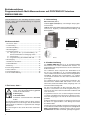
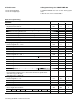
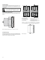
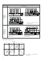
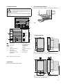
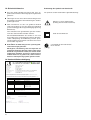
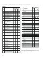
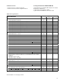
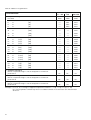
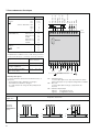
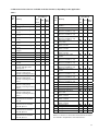
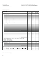
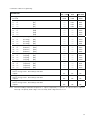
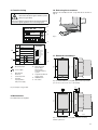
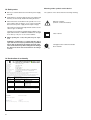
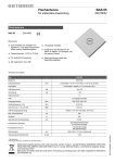
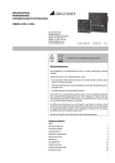
Betriebsanleitung SINEAX DME 406
Mode d’emploi SINEAX DME 406
Operating Instructions SINEAX DME 406
DME 406-1 Bd-f-e
Camille Bauer AG
Aargauerstrasse 7
CH-5610 Wohlen/Switzerland
Phone +41 56 618 21 11
Fax +41 56 618 21 21
[email protected]
www.camillebauer.com
02.14
2
Betriebsanleitung
Programmierbarer Multi-Messumformer mit
PROFIBUS-DP Interface
SINEAX DME 406 ............................................................................ 4
Mode d’emploi
Convertisseur de mesure multiple
programmable avec interface PROFIBUS-DP
SINEAX DME 406 .......................................................................... 17
Operating Instructions
Programmable multi-transducer with
PROFIBUS-DP Interface
SINEAX DME 406 .......................................................................... 30
Geräte dürfen nur fachgerecht entsorgt werden!
Les appareils ne peuvent être éliminés que de façon appropriée!
The instruments must only be disposed of in the correct way!
3
Betriebsanleitung
Programmierbarer Multi-Messumformer mit PROFIBUS-DP Interface
SINEAX DME 406
Sicherheitshinweise, die unbedingt beachtet werden
müssen, sind in dieser Betriebsanleitung mit folgenden
Symbolen markiert:
2. Lieferumfang
Messumformer (Bild 1)
1 leeres Typenschild (Bild 2), zum Eintragen der programmierten Daten
1 CD mit GSD-Datei, Betriebsanleitung dreisprachig (Deutsch,
Französisch, Englisch), Schnittstellen-Beschreibung und
Bitmap (Bild 3)
PROFIBUS
100V
2A
Inhaltsverzeichnis
50Hz
3N~
1
000
2. Lieferumfang ............................................................... 4
7. Elektrische Anschlüsse ............................................. 11
8. Inbetriebnahme ......................................................... 15
9. Wartung ..................................................................... 15
10. Demontage-Hinweis.................................................. 15
11. Mass-Skizzen ............................................................ 15
12. Sicherheitshinweise .................................................. 16
13. Konformitätserklärung ............................................... 16
1. Erst lesen, dann …
Der einwandfreie und gefahrlose Betrieb setzt
voraus, dass die Betriebsanleitung gelesen
und die in den Abschnitten
6. Befestigung
8. Inbetriebnahme
enthaltenen Sicherheitshinweise beachtet
werden.
Der Umgang mit diesem Gerät sollte nur durch entsprechend geschultes Personal erfolgen, das das Gerät kennt
und berechtigt ist, Arbeiten in regeltechnischen Anlagen
auszuführen.
Bei einem Eingriff in das Gerät erlischt der Garantieanspruch!
4
16
17
18
19
20
1. Erst lesen, dann … ..................................................... 4
3. Kurzbeschreibung ....................................................... 4
4. Bestellangaben ........................................................... 5
5. Technische Daten ........................................................ 5
5.1 Messgrössen, die – je nach Anwendung – an
der Busschnittstelle zur Verfügung stehen .......... 7
5.2 Zurücksetzen ....................................................... 8
5.3 Programmierung des SINEAX DME 406 .............. 8
6. Befestigung ............................................................... 10
15
2
21
22
23
3
24
4
26
25
VD
RxD/TxD –P
RxD/TxD –N
Shield
RxD/TxD –P'
RxD/TxD –N'
DGND
Reset
BF
BA
BD
GND
Bild 1
Bild 2
Bild 3
3. Kurzbeschreibung
Der SINEAX DME 406 (Bild 1) ist ein programmierbarer
Messumformer mit einem PROFIBUS-DP Interface zur
gleichzeitigen Erfassung mehrerer Grössen eines elektrischen
Starkstromnetzes.
Das zertifizierte Gerät entspricht der PROFIBUS Norm
EN 50 170. PROFIBUS ist ein herstellerunabhängiger,
offener Feldbusstandard mit breitem Anwendungsbereich.
PROFIBUS ermöglicht die Kommunikation von Geräten
verschiedener Hersteller ohne besondere Schnittstellenanpassungen.
Die charakteristischen Kommunikationsmerkmale des
Messumformers SINEAX DME 406 werden in Form einer
GSD-Datei (Gerätestammdaten-Datei) festgelegt und vom
Gerätehersteller bereitgestellt.
Die RS 232-Schnittstelle am Messumformer dient dazu,
mittels PC und Software sowohl die Programmierung vornehmen als auch interessante Zusatzfunktionen abrufen und
lösen zu können.
Programmieren lassen sich, um die wichtigsten Parameter
zu nennen: alle üblichen Anschlussarten, die Bemessungswerte der Eingangsgrössen und die Art der internen Energiezähler.
Zu den Zusatzfunktionen zählen u.a.: der Netz-System-Check,
der Druck von Typenschildern sowie Abfrage und Setzen
der Zählerstände.
Der Messumformer erfüllt die wichtigen Anforderungen und
Vorschriften hinsichtlich Elektromagnetischer Verträglichkeit
EMV und Sicherheit (IEC 1010 bzw. EN 61 010). Er ist nach
Qualitätsnorm ISO 9001 entwickelt, gefertigt und geprüft.
4. Bestellangaben
5. Technische Daten
MERKMAL
KENNUNG
1. Bauform
406 - 1
Gehäuse T24 für Schienen- und WandMontage
2. Nennfrequenz
50 Hz (60 Hz möglich ohne Zusatzfehler; 16 2/3 Hz, Zusatzfehler 1,25 %)
1
60 Hz (50 Hz möglich ohne Zusatzfehler; 16 2/3 Hz, Zusatzfehler 1,25 %)
2
16 2/3 Hz (Kundenseitig nicht umprogrammierbar, 50/60 Hz möglich, jedoch
Zusatzfehler 1,25 %)
3
Sinus
Nennfrequenz:
50, 60 oder 16 2/3 Hz
Eigenverbrauch [VA]
(bei externer
Hilfsenergie):
Spannungspfad: U2 / 400 kΩ
Strompfad: ≤ I2 · 0,01 Ω
Zulässige dauernd überhöhte Eingangsgrössen
10 A bei 400 V
im EinphasenWechselstromnetz
bei 693 V
im Drehstromnetz
Spannungspfad
DC/AC 24… 60 V
7
DC/AC 85… 230 V
8
4. Hilfsenergie, Anschluss
480 V Einphasen-Wechselstromnetz
831 V Drehstromnetz
Zulässige kurzzeitig überhöhte Eingangsgrössen
Anschluss extern (standard)
1
Anschluss intern ab Spannungseingang
2
Zeile 2: Nicht kombinierbar mit Nennfrequenz 16 2/3 Hz und Anwendungen
A15/A16/A24
Überhöhte
Eingangsgrösse
Strompfad
Achtung! Gewählte Hilfsenergiespannung
muss mit der Eingangsspannung,
Tabelle 2, übereinstimmen!
Anzahl
Dauer
Zeitraum
der Über- der Über- zwischen zwei
höhungen höhungen aufeinanderfolgenden
Überhöhungen
bei 400 V im Einphasen-Wechselstromnetz
bei 693 V im Drehstromnetz
5. Prüfprotokoll
Ohne Prüfprotokoll
0
Mit Prüfprotokoll in Deutsch
D
Mit Prüfprotokoll in Englisch
E
6. Konfiguration
Grundkonfiguration
0
Programmiert nach Auftrag
9
Zeile 9: Das ausgefüllte Formular
W 2410 d mit allen Programmierdaten ist
zwingender Bestandteil der Bestellung,
wenn Messwerte in Primärgrössen
oder Zählerwerte abgerufen werden
sollen.
Kurvenform:
Strompfad
3. Hilfsenergie
Zeile 0: Nicht zulässig mit HilfsenergieAnschluss intern ab Spannungseingang
Eingang
100 A
5
3s
5 Min.
250 A
1
1s
1 Stunde
Spannungspfad bei 1 A, 2 A, 5 A
EinphasenWechselstrom
600 V
bei Hintern: 1,5 Ur 10
10 s
10 s
Drehstrom
1040 V
bei Hintern: 1,5 Ur 10
10 s
10 s
PROFIBUS-DP (Busschnittstelle RS-485)
Busanschluss:
Schraubanschluss an Klemmen
15 bis 21
Protokoll:
PROFIBUS-DP EN 50 170
Protokoll-Chip:
SPC 41
Übertragungsrate:
9,6 kBaud … 12 MBaud
automatische Erkennung der Baudrate
Adresse:
126 (default), über
Set_Slave_Address einstellbar
Max. Buslänge:
100 … 1200 m (baudraten/kabelabhängig)
Schnittstelle:
RS 485, galvanisch getrennt
(500 V)
Konfigurier-Möglichkeit: Über PC vor Ort oder über Busmaster
5
Übertragungsverhalten
Programmier-Anschluss am Messumformer
Genauigkeitsklasse:
Schnittstelle:
RS 232 C
DSUB-Buchse:
9-polig
0,2 bzw. 0,4 bei Anwendungen mit
Kunstschaltung
Energiezähler:
1,0 nach IEC 1036
(0,1 Ir ≤ I ≤ 1,5 Ir)
Messzykluszeit:
Je nach Messgrösse und
Programmierung
Einstellzeit:
Ca. 1 … 2 Messzykluszeit
und 1…2 s
9
CTS
RTS
DSR
5
GND
DTR
TXD
RXD
Die Schnittstelle ist von allen anderen Kreisen galvanisch getrennt.
6 1
Einflussgrössen und Einflusseffekte
Einbauangaben
Gemäss EN 60 688
Bauform:
Gehäuse T24
Abmessungen siehe Abschnitt
«11. Mass-Skizzen»
Gehäusematerial:
Lexan 940 (Polycarbonat),
Brennbarkeitsklasse V-0 nach
UL 94, selbstverlöschend, nicht
tropfend, halogenfrei
Montage:
Für Schnappbefestigung auf Hutschiene (35 × 15 mm oder
35 × 7,5 mm) nach EN 50 022
Elektrische Sicherheit
Schutzklasse:
II
Berührungsschutz:
IP 40, Gehäuse
IP 20, Anschlussklemmen
Überspannungskategorie:
III
Nennisolationsspannung:
Eingang Spannung: AC 400 V
Stossspannungsfestigkeit:
Prüfspannung:
oder
Eingang Strom:
AC 400 V
Ausgang:
DC 40 V
Hilfsspannung:
AC 400 V
DC 230 V
5 kV; 1,2/50 μs; 0,5 Ws
50 Hz, 1 Min. nach
EN 61 010-1
3250 V, Eingangskreise gegeneinander
3700 V, Hilfsenergie gegen Ausgänge und SCI sowie Aussenfläche
490 V, Ausgänge und SCI gegeneinander und gegen Aussenfläche
Hilfsenergie
Leistungsaufnahme:
6
Gebrauchslage:
Beliebig
Anschlussklemmen
5550 V, Eingänge gegen alle anderen
Kreise sowie Aussenfläche
Spannung:
mit herausgezogenen Laschen
für direkte Wand-Montage durch
Schrauben
Gemäss Angabe auf dem Typenschild
DC, AC 24… 60 V
DC, AC 85…230 V
≤ 9 W bzw. ≤ 10 VA
Anschlusselement:
Schraubklemmen mit indirekter
Drahtpressung
Zulässiger Querschnitt
der Anschlussleitungen:
≤ 4,0 mm2 eindrähtig oder
2 × 2,5 mm2 feindrähtig
Umgebungsbedingungen
Nenngebrauchsbereich
für Temperatur:
0…15…30…45 °C
(Anwendungsgruppe II)
Betriebstemperatur:
– 10 bis + 55 °C
Lagerungstemperatur:
– 40 bis + 85 °C
Relative Feuchte
im Jahresmittel:
≤ 75%
Betriebshöhe:
2000 m max.
Nur in Innenräumen zu verwenden
5.1 Messgrössen, die – je nach Anwendung – an der Busschnittstelle zur Verfügung stehen
Tabelle 1:
SymErklärungen
bole
U
U12
U23
U31
U1N
U2N
U3N
UM
I
I1
I2
I3
IM
IMS
IB
IB1
IB2
IB3
BS
BS1
BS2
BS3
Eingangsspannung
Wechselspannung zwischen
den Aussenleitern L1 und L2
Wechselspannung zwischen
den Aussenleitern L2 und L3
Wechselspannung zwischen
den Aussenleitern L3 und L1
Wechselspannung zwischen
Aussenleiter L1 und
Sternpunkt N
Wechselspannung zwischen
Aussenleiter L2 und
Sternpunkt N
Wechselspannung zwischen
Aussenleiter L3 und
Sternpunkt N
Mittelwert der Spannungen
Eingangsstrom
Wechselstrom im
Aussenleiter L1
Wechselstrom im
Aussenleiter L2
Wechselstrom im
Aussenleiter L3
Mittelwert der Ströme
Mittelwert der Ströme mit
Vorzeichen der Wirkleistung
Effektivwert des Stromes
mit grosser Einstellzeit
(Bimetallmessfunktion)
Effektivwert des Stromes
mit grosser Einstellzeit
(Bimetallmessfunktion),
Phase 1
Effektivwert des Stromes
mit grosser Einstellzeit
(Bimetallmessfunktion),
Phase 2
Effektivwert des Stromes
mit grosser Einstellzeit
(Bimetallmessfunktion),
Phase 3
Schleppzeigerfunktion für
die Messung des
Effektivwertes IB
Schleppzeigerfunktion für
die Messung des
Effektivwertes IB, Phase 1
Schleppzeigerfunktion für
die Messung des
Effektivwertes IB, Phase 2
Schleppzeigerfunktion für
die Messung des
Effektivwertes IB, Phase 3
Anwendung
(siehe Tabelle 2)
A11
A24 /
…
A34
A44
A16
––
––
●
––
●
●
––
●
●
––
●
●
––
––
●
SymErklärungen
bole
F
P
P1
P2
P3
––
––
●
––
––
●
––
●
––
––
––
●
●
––
●
––
●
●
––
●
●
––
––
●
●
●
●
●
––
––
S
S1
––
●
●
S2
––
●
●
PF
PF1
PF2
PF3
Q
Q1
Q2
Q3
S3
––
●
●
●
––
––
––
●
●
––
●
●
––
●
●
LF
LF1
LF2
LF3
QF
QF1
QF2
QF3
EA
EB
EC
ED
Frequenz der
Eingangsgrösse
Wirkleistung des Netzes
Wirkleistung Strang 1
(Aussenleiter L1 und
Sternpunkt N)
Wirkleistung Strang 2
(Aussenleiter L2 und
Sternpunkt N)
Wirkleistung Strang 3
(Aussenleiter L3 und
Sternpunkt N)
Wirkfaktor cosϕ = P/S
Wirkfaktor Strang 1, P1/S1
Wirkfaktor Strang 2, P2/S2
Wirkfaktor Strang 3, P3/S3
Blindleistung des Netzes
Blindleistung Strang 1
(Aussenleiter L1 und
Sternpunkt N)
Blindleistung Strang 2
(Aussenleiter L2 und
Sternpunkt N)
Blindleistung Strang 3
(Aussenleiter L3 und
Sternpunkt N)
Scheinleistung des Netzes
Scheinleistung Strang 1
(Aussenleiter L1 und
Sternpunkt N)
Scheinleistung Strang 2
(Aussenleiter L2 und
Sternpunkt N)
Scheinleistung Strang 3
(Aussenleiter L3 und
Sternpunkt N)
Leistungsfaktor des Netzes
Leistungsfaktor Strang 1
Leistungsfaktor Strang 2
Leistungsfaktor Strang 3
Blindfaktor sinϕ = Q/S
Blindfaktor Strang 1, Q1/S1
Blindfaktor Strang 2, Q2/S2
Blindfaktor Strang 3, Q3/S3
Energiezähler 1
Energiezähler 2
Energiezähler 3
Energiezähler 4
Anwendung
(siehe Tabelle 2)
A11
A24 /
…
A34
A44
A16
●
●
●
●
––
●
––
●
●
––
––
●
––
––
●
●
––
––
––
●
––
●
––
––
––
●
––
●
●
●
●
●
●
––
––
●
––
––
●
●
––
●
––
●
●
––
––
●
––
––
●
●
––
––
––
●
––
––
––
●
●
●
●
●
––
––
––
●
––
––
––
●
●
●
●
●
●
●
●
●
●
●
●
●
●
●
●
Bei eingesetzten Strom- und/oder Spannungswandlern
beziehen sich die Messwerte immer auf die Primärseite der
Wandler.
7
5.2 Zurücksetzen
5.3 Programmierung des SINEAX DME 406
– Reset der Energiezähler
– Reset der Schleppzeiger
Der SINEAX DME 406 lässt sich auf zwei Arten programmieren:
1) über RS 232, mit PC Software DME 4
2) über PROFIBUS-DP Interface mit GSD-Datei
Tabelle 2: Programmierung
Anwendung
MERKMAL
A11 … A16
A34
A24 / A44
Einphasen-Wechselstrom
A11
–––
–––
Dreileiter-Drehstrom gleichbelastet, Kunstschaltung U: L1-L2, I: L1
A12
–––
–––
Dreileiter-Drehstrom gleichbelastet
A13
–––
–––
Vierleiter-Drehstrom gleichbelastet
A14
–––
–––
Dreileiter-Drehstrom gleichbelastet, Kunstschaltung U: L3-L1, I: L1
A15
–––
–––
Dreileiter-Drehstrom gleichbelastet, Kunstschaltung U: L2-L3, I: L1
A16
–––
–––
Dreileiter-Drehstrom ungleichbelastet
–––
A34
–––
Vierleiter-Drehstrom ungleichbelastet
–––
–––
A44
Vierleiter-Drehstrom ungleichbelastet, Open-Y
–––
–––
A24
Bemessungswert Ur = 57,7 V
U01
–––
–––
Bemessungswert Ur = 63,5 V
U02
–––
–––
Bemessungswert Ur = 100
V
U03
–––
–––
Bemessungswert Ur = 110
V
U04
–––
–––
Bemessungswert Ur = 120
V
U05
–––
–––
Bemessungswert Ur = 230
V
1. Anwendung (Netzform)
2. Eingangsspannung
Bemessungswert Ur
[V]
U06
–––
–––
U91
–––
–––
Bemessungswert Ur = 100
V
U21
U21
U21
Bemessungswert Ur = 110
V
U22
U22
U22
Bemessungswert Ur = 115
V
U23
U23
U23
Bemessungswert Ur = 120
V
U24
U24
U24
Bemessungswert Ur = 400
V
U25
U25
U25
Bemessungswert Ur = 500
V
U26
U26
U26
U93
U93
U93
Bemessungswert Ir = 1 A
V1
V1
V1
Bemessungswert Ir = 2 A
V2
V2
V2
Bemessungswert Ir = 5 A
V3
V3
V3
V9
V9
V9
Bemessungswert Ur
[V]
Zeilen U01 bis U06:
Nur für Einphasen-Wechselstrom oder Vierleiter-Drehstrom gleichbelastet
Zeile U91: Ur [V] 57 bis 400
Zeile U93: Ur [V] > 100 bis 693
3. Eingangsstrom
Bemessungswert Ir > 1 bis 6
[A]
4. Primärdaten (Primärwandler)
Ohne Angabe der Primärwerte
CT =
A / Ir
A
VT =
kV / Ur
Zeile W9: Wandlerdaten primär angeben, z.B. 1000 A; 33 kV
Fortsetzung der Tabelle 2 siehe nächste Seite
8
V
W0
W0
W0
W9
W9
W9
Fortsetzung der «Tabelle 2: Programmierung»
Anwendung
MERKMAL
A11 … A16
A34
A24 / A44
5. Energiezähler 1
Nicht belegt
EA00
EA00
EA00
I
Netz
[Ah]
EA50
–––
–––
I1
L1
[Ah]
–––
EA51
EA51
I2
L2
[Ah]
–––
EA52
EA52
I3
L3
[Ah]
–––
EA53
EA53
S
Netz
[VAh]
EA54
EA54
EA54
S1
L1
[VAh]
–––
–––
EA55
S2
L2
[VAh]
–––
–––
EA56
S3
L3
[VAh]
–––
–––
EA57
P
Netz
(Bezug)
[Wh]
EA58
EA58
EA58
P1
L1
(Bezug)
[Wh]
–––
–––
EA59
P2
L2
(Bezug)
[Wh]
–––
–––
EA60
P3
L3
(Bezug)
[Wh]
–––
–––
EA61
Q
Netz
(ind.)
[Varh]
EA62
EA62
EA62
Q1
L1
(ind.)
[Varh]
–––
–––
EA63
Q2
L2
(ind.)
[Varh]
–––
–––
EA64
Q3
L3
(ind.)
[Varh]
–––
–––
EA65
P
Netz
(Abgabe)
[Wh]
EA66
EA66
EA66
P1
L1
(Abgabe)
[Wh]
–––
–––
EA67
P2
L2
(Abgabe)
[Wh]
–––
–––
EA68
P3
L3
(Abgabe)
[Wh]
–––
–––
EA69
Q
Netz
(kap.)
[Wh]
EA70
EA70
EA70
Q1
L1
(kap.)
[Wh]
–––
–––
EA71
Q2
L2
(kap.)
[Wh]
–––
–––
EA72
Q3
L3
(kap.)
[Wh]
–––
–––
EA73
FA..
FA..
FA..
GA..
GA..
GA..
HA..
HA..
HA..
6. Energiezähler 2
Wie Energiezähler 1, jedoch beginnen die Kennungen mit dem
Grossbuchstaben F
7. Energiezähler 3
Wie Energiezähler 1, jedoch beginnen die Kennungen mit dem
Grossbuchstaben G
8. Energiezähler 4
Wie Energiezähler 1, jedoch beginnen die Kennungen mit dem
Grossbuchstaben H
Anmerkung: Bei I, I1, I2, I3 bezieht sich die Energie auf folgende Leistung: P = I · Up, I1 · Up, I2 · Up, I3 · Up.
Up = Primärnennspannung bzw. Sekundärnennspannung, falls kein Wandler vorhanden ist.
9
6. Befestigung
Die Befestigung des SINEAX DME 406 erfolgt wahlweise auf
einer Hutschiene oder direkt an einer Wand bzw. auf einer
Montagetafel.
Bei der Bestimmung des Montageortes müssen die «Umgebungsbedingungen», Abschnitt
«5. Technische Daten», eingehalten werden!
(1)
(1)
(2)
(3)
6.1 Montage auf Hutschiene
Gehäuse auf Hutschiene (EN 50 022) aufschnappen (siehe
Bild 4).
(2)
(5)
(4)
(1)
Bild 5. Geräteboden.
(1) Befestigungslaschen
(2) Schnappverschlüsse
(3) Gummipuffer
(1)
(4) Entriegelung zum Herausziehen
der Befestigungslaschen
(5) Entriegelung zum Hineinschieben
der Befestigungslaschen.
165
Gehäuse an Wand oder Montagetafel mit 2 Schrauben
4 mm ∅ befestigen. Löcher nach Bohrplan (Bild 6) bohren.
Bild 4. Montage auf Hutschiene 35 × 15 oder 35 × 7,5 mm.
6.2 Wandmontage
Die Befestigungslaschen (1) lassen sich nach Drücken der
Entriegelung (4) herausziehen. Nach Drücken der Entriegelung
(5) lassen sie sich wieder zurückschieben.
10
Bild 6. Bohrplan.
BD
GND
BF
BA
Reset
DGND
RxD/TxD -N’
RxD/TxD -P’
Anschluss
1/3
4/6
7/9
2
5
8
11
15
16
17
18
19
20
21
13
14
13
14
RxD/TxD -P
IL1
IL2
IL3
Wechselspannung UL1
UL2
UL3
N
RS 485
VP
(PROFIBUS DP)
RxD/TxD -P
RxD/TxD -N
Shield
RxD/TxD -P’
RxD/TxD -N’
DGND
Hilfsenergie AC
~
~
DC
+
–
VP
Funktion
Messeingang Wechselstrom
RxD/TxD -N
Shield
7. Elektrische Anschlüsse
Frontseite
15 16 17 18 19 20 21 22 23 24 25 26
RS 232
Bei Hilfsenergie ab Spannungseingang erfolgt
der interne Anschluss wie folgt:
Anwendung (Netzform)
Anschluss intern
Klemme / Netz
Einphasen-Wechselstrom
Vierleiter-Drehstrom
gleichbelastet
Alle übrigen (ausser
A15 / A16 / A24)
2 / 11
2 / 11
(L1 – N)
(L1 – N)
2/5
(L1 – L2)
1
2
IL1
3
4
5
6
7
8
9 11 13 14
IL1 IL2
IL2 IL3
IL3
N
UL1
UL2
UL3
–
Messeingang
Leitungsabschluss
Beide Enden des Buskabels müssen mit einem
Leitungs-abschluss versehen werden, damit ist
sichergestellt, dass
– ein definiertes Ruhepotential auf der Leitung
eingestellt ist,
– Leitungsreflexionen minimiert werden und
– ein nahezu konstantes Lastverhalten am Bus
eingestellt ist.
BF = LED BUS Failure
Der Slave ist im Zustand «Baud Search»und
empfängt keine gültigen Telegramme
BA = Bus Aktiv
Der Slave ist im zyklischen Datenaustausch
BD = LED Bus Diagnose
leuchtet:
Falsche Parametrierung
blinkt:
Falsche Konfiguration
Messeingänge
Netzformen /
Anwendung
Klemmenbelegung
EinphasenWechselstromnetz
(A11)
2
11
1
2
3
11
1
3
2
u
k
L1
N
N
K
1
L
3
v
l
k
U
L1
11
L1
l
V
K
L
N
11
Messeingänge
Netzformen /
Anwendung
Klemmenbelegung
2
5
8
1
3
2
5
8
1
3
k
DreileiterDrehstromnetz
gleichbelastet
I: L1
(A13)
2
8
5
u
v
u
v
U
V
U
V
l
l
k
L1
L1
L2
L2
L2
L3
L3
L3
K
3
1
L
L1
K
L
Bei Strommessung über L2 bzw. L3, Spannungsanschluss nach folgender Tabelle vornehmen:
Stromwandler
Klemmen
2
5
8
L2
1
3
L2
L3
L1
L3
1
3
L3
L1
L2
2
DreileiterDrehstromnetz
gleichbelastet
Kunstschaltung
U: L1 – L2
I: L1
(A12)
5
1
2
3
5
1
2
3
u
k
L2
L1
L2
L3
L3
L1
L
1
3
v
k
l
K
5
U
l
V
L1
L2
K
L
L3
Bei Strommessung über L2 bzw. L3, Spannungsanschluss nach folgender Tabelle vornehmen:
Stromwandler
Klemmen
2
5
L2
1
3
L2
L3
L3
1
3
L3
L1
8
2
1
3
8
2
1
3
8
u
DreileiterDrehstromnetz
gleichbelastet
Kunstschaltung
U: L3 – L1
I: L1
(A15)
k
L1
L2
L2
L1
L2
L3
L3
L3
L
3
v
k
L1
l
V
K
Bei Strommessung über L2 bzw. L3, Spannungsanschluss nach folgender Tabelle vornehmen:
Stromwandler
12
1
l
U
K
2
Klemmen
8
2
L2
1
3
L1
L2
L3
1
3
L2
L3
L
Messeingänge
Netzformen /
Anwendung
Klemmenbelegung
5
8
1
5
3
8
1
5
3
8
u
k
DreileiterDrehstromnetz
gleichbelastet
Kunstschaltung
U: L2 – L3
I: L1
(A16)
3
v
k
l
U
L1
L1
L2
L2
L1
L2
L3
L3
L3
K
L
l
V
K
L
Bei Strommessung über L2 bzw. L3, Spannungsanschluss nach folgender Tabelle vornehmen:
Stromwandler
Klemmen
5
8
L2
1
3
L3
L1
L3
1
3
L1
L2
2
11
1
2
3
11
1
3
2
11
u
k
1
k
L1
L1
L2
L2
L1
L2
L3
L3
L3
N
N
N
K
3
v
l
U
VierleiterDrehstromnetz
gleichbelastet
I: L1
(A14)
1
L
l
V
K
L
Bei Strommessung über L2 bzw. L3, Spannungsanschluss nach folgender Tabelle vornehmen:
Stromwandler
Klemmen
2
11
L2
1
3
L2
N
L3
1
3
L3
N
2
8
5
3
1
9
7
2
5
8
3
1
k
DreileiterDrehstromnetz
ungleichbelastet
(A34)
L1
L1
L2
L2
L3
L3
2
L1
8
5
u
u
1
3
7
K
7
2
9
8
5
1
u
v
u
v
U
V
U
V
k
l
L
k
l
L1
K
3
7
9
l
L
k
l
L2
K
L
L3
K
L
9
u
x
x
x
X
X
X
U
U
U
k
K
l
k
L
l
L2
L3
K
L
13
Messeingänge
Netzformen /
Anwendung
Klemmenbelegung
2
8
5
1
11
4
3
6
9
7
2
5
8
1
11
4
3
k
6
l
k
L1
L1
L2
L2
L3
L3
N
VierleiterDrehstromnetz
ungleichbelastet
(A44)
9
7
K
l
k
L
K
l
L
K
L
N
2
L1
8
5
1
11
u
u
u
x
x
x
X
X
X
U
U
U
4
3
k
6
9
7
l
k
K
l
k
L
L2
K
l
L
L3
K
3 einpolig isolierte Spannungswandler im
Hochspannungsnetz
L
N
1
2
8
1
11
4
3
6
3
2
5
4
7
6
8
9 11
9
7
u u
x x
VierleiterDrehstromnetz
ungleichbelastet,
Open-YSchaltung
(A24)
k
l
k
L1
K
l
k
L
L2
K
L3
k
XX
L1
l
L2
L
K
L3
L
k
l
k
l
l
UU
K
L
L
K
L
K
N
N
Niederspannungsnetz
2 einpolig isolierte Spannungswandler im
Hochspannungsnetz
L
Unterscheidung von PF, QF und LF
Ausgang
ind.
kap.
kap.
ind.
QF
PF
–180
–90
0
90
180
ϕ
LF
Abgabe
14
Bezug
Abgabe
Bild 7. Wirkfaktor PF ––––, Blindfaktor QF -----,
Leistungsfaktor LF – · – · – .
8. Inbetriebnahme
10. Demontage-Hinweis
Messumformer gemäss Bild 9 von Tragschiene abnehmen.
Vor der Inbetriebnahme überprüfen, ob die
Anschlussdaten des Messumformers mit
den Daten der Anlage übereinstimmen (siehe
Typenschild).
Danach kann der Messumformer in Betrieb genommen
werden.
SINEAX DME 406
Camille Bauer AG
CH - 5610 Wohlen
Switzerland
7
Ord: 146911/4444444
13
14
AC/DC 85…230 V
50/60Hz 10VA
8
IL1 1 3
IL2 4 6
IL3 7 9
13 14
1 2 3 4 5 6 7 8 9 11
6
UL1 2
UL2 5
UL3 8
Bild 9
N 11
9
PROFIBUS
100V
18
3N~
19
20
11
000
1
P
R
2
Q
L
3
P1
R
4
I1
Messeingang
21
22
23
24
25
26
Hersteller
7
Fabrikations-Nummer
8
Prüfzeichen
9
Klemmenbelegung
Eingangsgrössen und
Hilfsenergie
11. Mass-Skizzen
15 16 17 18 19 20 21 22 23 24 25 26
13
10
Messeingang
Eingangsspannung
Eingangsstrom
Nennfrequenz
Netzform
11
Programmierte interne
Zähler
12
PROFIBUS DP
13
Bus status
Hilfsenergie
6
12
1 2 3 4 5 6 7 8 9 11 13 14
124
87,5
Bild 10. SINEAX DME im Gehäuse T24 auf Hutschiene
(35 ×15 mm oder 35×7,5 mm, nach EN 50 022) aufgeschnappt.
Bild 8. Beispiel eines Typenschildes.
6,5
19
Ø 4,5
17
50Hz
VD
RxD/TxD –P
RxD/TxD –N
Shield
RxD/TxD –P'
RxD/TxD –N'
DGND
Reset
BF
BA
BD
GND
157
10
16
150
15
2A
15 16 17 18 19 20 21 22 23 24 25 26
9. Wartung
181
165
150
Der Messumformer ist wartungsfrei.
1 2 3 4 5 6 7 8 9 11 13 14
12
87,5
123,4
Bild 11. SINEAX DME im Gehäuse T24 mit herausgezogenen
Laschen für direkte Wandmontage.
15
12. Sicherheitshinweise
Bedeutung der Symbole auf dem Gerät
● Bevor das Gerät in Betrieb genommen wird, muss geprüft werden, für welche Hilfsenergiespannung das Gerät
gebaut ist.
Die Symbole auf dem Gerät haben folgende Bedeutung:
● Überzeugen Sie sich, dass die Anschlussleitungen nicht
beschädigt und während der Verdrahtung des Gerätes
spannungsfrei sind.
Warnung vor einer Gefahrenstelle
(Achtung, Dokumentation beachten!)
● Wenn anzunehmen ist, dass ein gefahrloser Betrieb
nicht mehr möglich ist, muss das Gerät ausser Betrieb
gesetzt werden (ggf. Hilfsenergie und Eingangsspannung
abklemmen!).
Diese Annahme kann grundsätzlich getroffen werden,
wenn das Gerät sichtbare Schäden aufweist.
Gerät der Schutzklasse II
Eine Wiederinbetriebnahme des Gerätes ist erst nach
einer Fehlersuche, Instandsetzung und einer abschliessenden Überprüfung der Kalibrierung und der Spannungsfestigkeit in unserem Werk oder durch eine unserer
Servicestellen zugelassen.
● Beim Öffnen der Abdeckung können spannungsführende Teile freigelegt werden.
Ein Abgleich, eine Wartung oder eine Reparatur am
geöffneten Gerät unter Spannung darf nur durch eine
Fachkraft vorgenommen werden, die mit den damit
verbundenen Gefahren vertraut ist. Kondensatoren
im Gerät können noch geladen sein, selbst wenn das
Gerät von allen Spannungsquellen getrennt wurde.
13. Konformitätsbescheinigung
EG - KONFORMITÄTSERKLÄRUNG
DECLARATION OF CONFORMITY
Dokument-Nr./
Document.No.:
DME406_CE-konf.DOC
Hersteller/
Manufacturer:
Camille Bauer AG
Switzerland
Anschrift /
Address:
Aargauerstrasse 7
CH-5610 Wohlen
Produktbezeichnung/
Product name:
Programmierbarer Multi-Messumformer mit PROFIBUS-DP
Programmable Multi-Transducers with PROFIBUS-DP
Typ / Type:
SINEAX DME 406
Das bezeichnete Produkt stimmt mit den Vorschriften folgender Europäischer Richtlinien
überein, nachgewiesen durch die Einhaltung folgender Normen:
The above mentioned product has been manufactured according to the regulations of the following European directives proven through compliance with the following standards:
Nr. / No.
R i c h t l i n i e / D i r e c t i ve
2004/108/EG
2004/108/EC
Elektromagnetische Verträglichkeit - EMV - Richtlinie
Electromagnetic compatibility -EMC directive
EMV /
EMC
Fachgrundnorm /
Generic Standard
Störaussendung /
Emission
Störfestigkeit /
Immunity
EN 61000-6-4 : 2007
EN 55011 : 2007+A2:2007
EN 61000-6-2 : 2005
IEC
IEC
IEC
IEC
IEC
IEC
Nr. / No.
R i c h t l i n i e / D i r e c t i ve
2006/95/EG
E l e k t r i s c h e B e t r i e b s m i t t e l z u r V e r we n d u n g i n n e r h a l b b e s t i m m t e r S p a n n u n g s grenzen – Niederspannungsrichtlinie – CE-Kennzeichnung : 95
E l e c t r i c a l e q u i p m e n t f o r u s e wi t h i n c e r t a i n v o l t a g e l i m i t s – L o w V o l t a g e D i r e c tive – Attachment of CE mark : 95
2006/95/EC
M e s s ve r f a h r e n /
Measurement methods
61000-4-2: 1995+A1:1998+A2:2001
61000-4-3: 2006+A1:2007
61000-4-4: 2004
61000-4-5: 2005
61000-4-6: 2008
61000-4-11: 2004
EN/Norm/Standard IEC/Norm/Standard
EN 61 010-1 : 2001
IEC 1010-1 : 2001
Ort, Datum /
Place, date:
Wohlen, 20.Januar 2010
Unterschrift / signature:
M. Ulrich
J. Brem
Leiter Technik / Head of engineering
Qualitätsmanager / Quality manager
16
CSA geprüft für USA und Kanada
file-nr. 204 767
Mode d’emploi
Convertisseur de mesure multiple programmable avec
interface PROFIBUS-DP, SINEAX DME 406
Les conseils de sécurité qui doivent impérativement être
observés sont marqués des symboles ci-contre dans le
présent mode d’emploi:
2. Etendue de la livraison
Convertisseur de mesure (Fig. 1)
1 plaquette signalétique vierge (Fig. 2), pour noter les
caractéristiques programmées
1 CD avec fichier GSD, mode d’emploi en trois langues
(allemand, français, anglais), définition de l’interface et
Bitmap (Fig. 3)
PROFIBUS
100V
2A
Sommaire
50Hz
3N~
15
16
17
18
19
20
1
1. A lire en premier, ensuite … ..................................... 17
000
2. Etendue de la livraison .............................................. 17
3. Description brève ...................................................... 17
4. Références de commande ........................................ 18
5. Caractéristiques techniques ..................................... 18
5.1 Grandeurs de mesure disponibles – selon
l’application – au bus informatique .................... 20
5.2 Remise à zéro .................................................... 21
5.3 Programmation du convertisseur de mesure
SINEAX DME 406............................................... 21
6. Fixation ...................................................................... 23
7. Raccordements électriques ...................................... 24
8. Mise en service ......................................................... 28
9. Maintenance.............................................................. 28
10. Instructions pour le démontage ................................ 28
11. Croquis d’encombrements........................................ 28
12. Consignes de sécurité .............................................. 29
13. Certificat de conformité ............................................ 29
Fig. 1
2
21
22
23
3
24
4
26
25
VD
RxD/TxD –P
RxD/TxD –N
Shield
RxD/TxD –P'
RxD/TxD –N'
DGND
Reset
BF
BA
BD
GND
Fig. 2
Fig. 3
3. Description brève
Le SINEAX DME 406 (Fig. 1) est un convertisseur de mesure programmable avec une interface PROFIBUS-DP pour
le captage simultané de plusieurs grandeurs d’un réseau
électrique courant fort.
L’appareil certifié correspond à la norme PROFIBUS
EN 50 170. PROFIBUS est une norme d’un bus informatique
ouvert, indépendant d’un fabricant déterminé. PROFIBUS
permet la communication d’appareils de provenance diverse sans qu’il soit nécessaire d’adapter spécialement les
interfaces.
Les caractéristiques de communication du convertisseur de
mesure SINEAX DME 406 sont fixées dans la forme d’un fichier
GSD (Gerätestammdaten-Datei = fichier des caractéristiques
de base de l’appareil) et déterminées par l’usine.
1. A lire en premier, ensuite …
Pour un fonctionnement sûr et sans danger, il
est essentiel de lire le présent mode d’emploi
et de respecter les recommandations de
sécurité mentionnées dans les rubriques
6. Fixation
8. Mise en service.
Ces appareils devraient uniquement être manipulés par
des personnes qui les connaissent et qui sont autorisées
à travailler sur des installations techniques du réglage.
Toute intervention dans l’appareil entraîne l’extinction de
la clause de garantie!
L’interface RS 232 du convertisseur de mesure sert à l’aide
d’un logiciel et d’un PC à la programmation et permet en
plus de réaliser certaines fonctions additionnelles intéressantes.
Voici un aperçu des possibilités de programmation les plus
importantes: tous les systèmes de raccordement usuels,
les valeurs des grandeurs d’entrée et le genre du compteur
interne d’énergie.
Parmi les fonctions additionnelles, il faut mentionner entre
autres: vérification du système de réseau, l’impression de
plaquettes signalétiques ainsi que demander et présélectionner l’état des compteurs.
Le convertisseur de mesure satisfait aux exigences
et prescriptions en ce qui concerne la compatibilité
électromagnétique EMC et Sécurité (CEI 1010 resp.
EN 61 010). Il est développé, fabriqué et contrôlé selon la
norme de qualité ISO 9001.
17
4. Références de commande
CARACTERISTIQUE
1. Construction
5. Caractéristiques techniques
DESIGNATION
406 - 1
Boîtier T24 pour montage sur rail ou
sur paroi
2. Fréquence nominale
50 Hz (60 Hz possible sans erreur
additionnelle; 16 2/3 Hz, erreur
additionnelle 1,25 %)
1
60 Hz (50 Hz possible sans erreur
additionnelle; 16 2/3 Hz, erreur
additionnelle 1,25 %)
2
16 2/3 Hz (programmation par le
client pas possible, 50/60 Hz
possible, mais erreur additionnelle
1,25 %)
3
Entrée
Forme de la courbe:
Sinusoïdale
Fréquence nominale:
50, 60 ou 16 2/3 Hz
Consommation propre [VA]
(avec alimentation
auxiliaire externe):
Circuit de tension: U2 / 400 kΩ
Circuit d’intensité: ≤ I2 · 0,01 Ω
Augmentation permanente admissible des grandeurs
d’entrée
Circuit
d’intensité
3. Alimentation auxiliaire
CC/CA 24… 60 V
7
CC/CA 85…230 V
8
10 A à 400 V
dans réseau de courant
alternatif monophasé
à 693 V
dans réseau de courant
triphasé
480 V Réseau de courant alternatif
monophasée
Circuit de
tension
831 V Réseau de courant triphasé
4. Alimentation aux., raccordement
Raccordement externe (standard)
1
Raccordement interne via tension
d’entrée
2
Ligne 2: Pas combinable avec fréquence nominale 16 2/3 Hz et applications A15/A16/A24
Grandeur
d’entrée
augmentée
Circuit
d’intensité
Attention! La tension d’alimentation
choisie doit correspondre à la tension
d’entrée, voir tableau 2!
5. Procès-verbal d’essai
Sans procès-verbal d’essai
0
Avec procès-verbal d’essai en
allemand
D
Avec procès verbal d’essai en
anglais
E
6. Configuration
Configuration de base
0
Programmation selon l’ordre
9
Ligne 0: Non réalisable avec raccordement interne de l’alimentation via
tension d’entrée
Ligne 9: Le bulletin de commande
W 2410 f avec toutes les données de
programmation fait partie intégrante
de la commande, pour les cas du
choix des valeurs de mesure et des
états des compteurs selon les rapports primaires.
Augmentation temporaire admissible des grandeurs
d’entrée
Nombre
Durée des Intervalle entre
d’augmen- augmen- deux augmentations
tations
tations successives
à 400 V dans réseau de courant
alternatif monophasé
à 693 V dans réseau de courant triphasé
100 A
5
3s
5 min.
250 A
1
1s
1 heure
Circuit de tension à 1 A, 2 A, 5 A
Courant alternatif monophasé
600 V
10 s
10 s
à Hinterne: 1,5 Ur 10
Courant triphasé
1040 V
10 s
10 s
à Hinterne: 1,5 Ur 10
PROFIBUS-DP (bus informatique RS-485)
Raccordement du bus: Bornes à visser 15 à 21
Protocole:
PROFIBUS-DP EN 50 170
Puce de protocole:
SPC 41
Vitesse de transmission: 9,6 kBaud … 12 MBaud
détermination automatique de la
gamme
Adresse:
126 (default), ajustable par
Set_Slave_Address
Longueur max. du bus: 100 … 1200 m (dépend de la vitesse
Baud et du câble utilisé)
Interface:
Possibilités de
configuration:
18
RS 485, séparée galvaniquement
(500 V)
Par PC sur le site ou par unité principale du bus
Caractéristiques de transmission
Classe de protection:
Compteur d’énergie:
Durée du cycle de
mesure:
Temps de réponse:
0,2 resp. 0,4 en application avec
phase artificielle
1,0 selon CEI 1036
(0,1 Ir ≤ I ≤ 1,5 Ir)
Selon grandeur mesurée et programmation
Env. 1 … 2 durées du cycle de
mesure et 1…2 s
Connecteur de programmation du convertisseur
de mesure
Interface:
RS 232 C
Douille DSUB:
9-pôles
9
CTS
RTS
DSR
5
GND
DTR
TXD
RXD
L’interface est galvaniquement séparée de tous les autres circuits.
6 1
Effets et grandeurs d’influence
Présentation, montage, raccordement
Selon EN 60 688
Construction:
Boîtier T24
Dimensions voir paragraphe
«11. Croquis d’encombrements»
Matériau du boîtier:
Lexan 940 (polycarbonate),
classe d’inflammabilité V-0 selon
UL 94, à auto-extinction, ne gouttant pas, exempt d’halogène
Montage:
Pour fixation sur barre à profil en
chapeau (35 × 15 mm ou
35 × 7,5 mm) selon EN 50 022
Sécurité électrique
Classe de protection:
II
Protection:
IP 40, boîtier
IP 20, bornes de raccordement
Catégorie de
surtension:
III
Tension nominale
d’isolement:
Entrée tension:
CA 400 V
Entrée courant:
CA 400 V
Sortie:
CC 40 V
Position d’utilisation:
CA 400 V
CC 230 V
Bornes de raccordement
ou
Alimentation
auxiliaire:
Résistance aux tension
transitoires:
5 kV; 1,2/50 μs; 0,5 Ws
Tension d’essai:
50 Hz, 1 min. selon
EN 61 010-1
5550 V, entrées contre tous les autres
circuits et la surface extérieure
3700 V, alimentation auxiliaire contre
les sorties et SCI et contre la surface
extérieure
Domaine nominal
d’utilisation pour
température:
Selon plaquette signalétique
CC, CA 24… 60 V
CC, CA 85…230 V
≤ 9 W resp. ≤ 10 VA
Quelconque
Bornes à vis pour pression indirecte
des fils
Section admissible
pour fils de connexion: ≤ 4,0 mm2 monoconducteur ou
2 × 2,5 mm2 conducteur souple
Ambiance extérieure
Alimentation auxiliaire
Consommation:
Eléments de
raccordement:
3250 V, circuits d’entrée entre eux
490 V, sorties et SCI contre la surface
extérieure
Tension:
avec languettes extraites pour
montage mural par vis de fixation
0…15…30…45 °C
(Groupe d’utilisation II)
Température de
fonctionnement:
– 10 à + 55 °C
Température de
stockage:
– 40 à + 85 °C
Humidité relative en
moyenne annuelle:
≤ 75%
Altitude:
2000 m max.
Utilisation intérieure!
19
5.1 Grandeurs de mesure disponibles – selon l’application – au bus informatique
Tableau 1:
SymSignification
bole
U
U12
U23
U31
U1N
U2N
U3N
UM
I
I1
I2
I3
IM
IMS
IB
IB1
IB2
IB3
BS
BS1
BS2
BS3
20
Tension d’entrée
Tension alternative entre les
phases externes L1 et L2
Tension alternative entre les
phases externes L2 et L3
Tension alternative entre les
phases externes L3 et L1
Tension alternative entre la
phase externe L1 et
le point neutre N
Tension alternative entre la
phase externe L2 et
le point neutre N
Tension alternative entre la
phase externe L3 et
le point neutre N
Valeur moyenne des
tensions
Courant d’entrée
Courant alternatif dans la
phase externe L1
Courant alternatif dans la
phase externe L2
Courant alternatif dans la
phase externe L3
Valeur moyenne des
intensités
Valeur moyenne des intensités avec signe de polarité de
la puissance efficace
Valeur efficace de l’intensité
avec temps de réglage prolongé (fonction de mesure
bilame)
Valeur effective de l’intensité
avec temps de réglage prolongé (fonction de mesure
bilame), phase 1
Valeur effective de l’intensité
avec temps de réglage prolongé (fonction de mesure
bilame), phase 2
Valeur effective de l’intensité
avec temps de réglage prolongé (fonction de mesure
bilame), phase 3
Fonction d’aiguille entraînée
pour la mesure de la valeur
effective IB
Fonction d’aiguille entraînée
pour la mesure de la valeur
effective IB, phase 1
Fonction d’aiguille entraînée
pour la mesure de la valeur
effective IB, phase 2
Fonction d’aiguille entraînée
pour la mesure de la valeur
effective IB, phase 3
Application
(voir tableau 2)
A11
A24 /
…
A34
A44
A16
––
––
●
––
●
●
SymSignification
bole
F
P
P1
––
●
●
––
●
●
P2
––
––
●
P3
––
––
●
PF
PF1
––
––
●
PF2
––
––
●
●
––
––
●
––
●
––
●
●
––
●
●
Q3
––
●
●
––
●
●
S
S1
PF3
Q
Q1
Q2
S2
●
––
––
––
●
●
––
●
●
––
●
●
S3
LF
LF1
LF2
LF3
QF
QF1
QF2
QF3
●
––
––
––
●
●
––
●
●
––
●
●
EA
EB
EC
ED
Fréquence de la grandeur
d’entrée
Puissance active du réseau
Puissance active, branche 1
(phase L1 et point neutre N)
Puissance active, branche 2
(phase L2 et point neutre N)
Puissance active, branche 3
(phase L3 et point neutre N)
Facteur actif cosϕ = P/S
Facteur actif, branche 1, P1/
S1
Facteur actif, branche 2, P2/
S2
Facteur actif, branche 3, P3/
S3
Puiss. réactive du réseau
Puiss. réactive, branche 1
(phase L1 et point neutre N)
Puiss. réactive, branche 2
(phase L2 et point neutre N)
Puiss. réactive, branche 3
(phase L3 et point neutre N)
Puiss. apparente du réseau
Puiss. apparente, branche 1
(phase L1 et point neutre N)
Puiss. apparente, branche 2
(phase L2 et point neutre N)
Puiss. apparente, branche 3
(phase L3 et point neutre N)
Facteur de puiss. du réseau
Facteur de puiss., branche 1
Facteur de puiss., branche 2
Facteur de puiss., branche 3
Facteur réactif sinϕ = Q/S
Facteur réactif, branche 1,
Q1/S1
Facteur réactif, branche 2,
Q2/S2
Facteur réactif, branche 3,
Q3/S3
Compteur d’énergie 1
Compteur d’énergie 2
Compteur d’énergie 3
Compteur d’énergie 4
Application
(voir tableau 2)
A11
A24 /
…
A34
A44
A16
●
●
●
●
––
●
––
●
●
––
––
●
––
––
●
●
––
●
––
●
●
––
––
●
––
––
●
●
––
●
––
●
●
––
––
●
––
––
●
●
––
●
––
●
●
––
––
●
––
––
●
●
––
––
––
●
––
●
––
––
––
●
––
●
●
●
●
●
●
––
––
●
––
––
●
●
●
●
●
●
●
●
●
●
●
●
●
Avec l’emploi de transformateurs d’intensité et/ou de tension, les valeurs de mesures se rapportent toujours au côté
primaire des transformateurs.
5.2 Remise à zéro
5.3 Programmation du SINEAX DME 406
– Remise à zéro des compteurs d’énergie
– Remise à zéro de la fonction d’aiguille entraînée
La programmation du SINEAX DME 406 peut être réalisée
de deux façons différentes:
1) par RS 232, avec logiciel PC DME 4
2) par interface PROFIBUS-DP avec fichier GSD
Tableau 2: Programmation
Application
CARACTERISTIQUE
A11 … A16
A34
A24 / A44
Courant alternatif monophasé
A11
–––
–––
Courant triphasé 3 fils à charges équilibrées, phase artificielle U: L1-L2, I: L1
A12
–––
–––
Courant triphasé 3 fils à charges équilibrées
A13
–––
–––
Courant triphasé 4 fils à charges équilibrées
A14
–––
–––
Courant triphasé 3 fils à charges équilibrées, phase artificielle U: L3-L1, I: L1
A15
–––
–––
Courant triphasé 3 fils à charges équilibrées, phase artificielle U: L2-L3, I: L1
A16
–––
–––
Courant triphasé 3 fils à charges déséquilibrées
–––
A34
–––
Courant triphasé 4 fils à charges déséquilibrées
–––
–––
A44
Courant triphasé 4 fils à charges déséquilibrées, open-Y
–––
–––
A24
Valeur référence Ur = 57,7 V
U01
–––
–––
Valeur référence Ur = 63,5 V
U02
–––
–––
Valeur référence Ur = 100
V
U03
–––
–––
Valeur référence Ur = 110
V
U04
–––
–––
Valeur référence Ur = 120
V
U05
–––
–––
Valeur référence Ur = 230
V
U06
–––
–––
1. Application (réseau)
2. Tension d’entrée
Valeur référence Ur
U91
–––
–––
Valeur référence Ur = 100
V
[V]
U21
U21
U21
Valeur référence Ur = 110
V
U22
U22
U22
Valeur référence Ur = 115
V
U23
U23
U23
Valeur référence Ur = 120
V
U24
U24
U24
Valeur référence Ur = 400
V
U25
U25
U25
Valeur référence Ur = 500
V
U26
U26
U26
U93
U93
U93
Valeur référence Ir = 1 A
V1
V1
V1
Valeur référence Ir = 2 A
V2
V2
V2
Valeur référence Ir = 5 A
V3
V3
V3
V9
V9
V9
W0
W0
W0
W9
W9
W9
Valeur référence Ur
[V]
Ligne U01 à U06:
Seulement pour courant monophasé ou courant triphasé à 4 fils à charges
équilibrées
Ligne U91: Ur [V] 57 à 400
Ligne U93: Ur [V] > 100 à 693
3. Courant d’entrée
Valeur référence Ir > 1 à 6
[A]
4. Valeurs primaires (transformateur primaire)
Sans spécification des valeurs primaires
CT =
A / Ir
A
VT =
kV / Ur
V
Ligne W9: Indiquer rapport de transformation primaire, p.ex. 1000 A; 33 kV
Suite du tableau 2 voir à la page suivante
21
Suite du «Tableau 2: Programmation»
Application
CARACTERISTIQUE
A11 … A16
A34
A24 / A44
EA00
EA00
EA00
5. Compteur d’énergie 1
Non utilisé
I
Réseau
[Ah]
EA50
–––
–––
I1
L1
[Ah]
–––
EA51
EA51
I2
L2
[Ah]
–––
EA52
EA52
I3
L3
[Ah]
–––
EA53
EA53
S
Réseau
[VAh]
EA54
EA54
EA54
S1
L1
[VAh]
–––
–––
EA55
S2
L2
[VAh]
–––
–––
EA56
S3
L3
[VAh]
–––
–––
EA57
P
Réseau
(reçu)
[Wh]
EA58
EA58
EA58
P1
L1
(reçu)
[Wh]
–––
–––
EA59
P2
L2
(reçu)
[Wh]
–––
–––
EA60
P3
L3
(reçu)
[Wh]
–––
–––
EA61
Q
Réseau
(ind.)
[Varh]
EA62
EA62
EA62
Q1
L1
(ind.)
[Varh]
–––
–––
EA63
Q2
L2
(ind.)
[Varh]
–––
–––
EA64
Q3
L3
(ind.)
[Varh]
–––
–––
EA65
P
Réseau
(fourni)
[Wh]
EA66
EA66
EA66
P1
L1
(fourni)
[Wh]
–––
–––
EA67
P2
L2
(fourni)
[Wh]
–––
–––
EA68
P3
L3
(fourni)
[Wh]
–––
–––
EA69
Q
Réseau
(cap.)
[Wh]
EA70
EA70
EA70
Q1
L1
(cap.)
[Wh]
–––
–––
EA71
Q2
L2
(cap.)
[Wh]
–––
–––
EA72
Q3
L3
(cap.)
[Wh]
–––
–––
EA73
FA..
FA..
FA..
GA..
GA..
GA..
HA..
HA..
HA..
6. Compteur d’énergie 2
Idem au compteur d’énergie 1, mais les désignations commencent
par la lettre F
7. Compteur d’énergie 3
Idem au compteur d’énergie 1, mais les désignations commencent
par la lettre G
8. Compteur d’énergie 4
Idem au compteur d’énergie 1, mais les désignations commencent
par la lettre H
Remarque: Pour I, I1, I2, I3, l’énergie se rapporte à la puissance suivante: P = I · Up, I1 · Up, I2 · Up, I3 · Up.
Up = Tension primaire nominale resp. tension secondaire nominale en cas de mesure sans transformateur
de tension.
22
6. Fixation
Les SINEAX DME 406 peuvent être au choix montés sur
des rails «à chapeau» ou directement sur une surface de
montage.
En déterminant l’emplacement de montage, il
faut tenir compte des indications fournis sous
le rubrique «Ambiance extérieure» du chapitre
«5. Caractéristiques techniques»!
(1)
(1)
(2)
(3)
(2)
6.1 Montage sur rail «à chapeau»
Encliqueter le boîtier sur le rail «à chapeau» (EN 50 022)
(voir Fig. 4).
(5)
(4)
(1)
Fig. 5. Fond de l’appareil.
(1) Languettes de fixation
(2) Cliquets de retenus
(3) Tampons en caoutchouc
(1)
(4) Verrouillage pour
languettes rentrées
(5) Verrouillage pour
languettes extraites.
165
Fixer le boîtier à l’aide de 2 vis 4 mm ∅ sur la paroi ou sur
le tableau de montage. Perçer les trous selon le plan de
perçage (Fig. 6).
Fig. 4. Montage sur rail «à chapeau» 35 × 15 ou 35 × 7,5 mm.
6.2 Montage mural
Tirer en dehors les languettes de fixation (1) en enfonçant
en même temps le bouton de verrouillage (4) (voir Fig. 5 à
gauche). Pour rentrer si nécessaire les languettes de fixation, il faut enfoncer le bouton de verrouillage (5) et en même
temps glisser les languettes de fixation (1) dans la base du
boîtier (voir Fig. 5 à droite).
Fig. 6. Plan de perçage.
23
BD
GND
BF
BA
Remise à zéro
DGND
RxD/TxD -N’
Connexion
1/3
4/6
7/9
2
5
8
11
15
16
17
18
19
20
21
13
14
13
14
RxD/TxD -P’
IL1
IL2
IL3
Tension alternative UL1
UL2
UL3
N
RS 485
VP
(PROFIBUS DP)
RxD/TxD -P
RxD/TxD -N
Shield
RxD/TxD -P’
RxD/TxD -N’
DGND
Alimentation CA
~
auxiliaire
~
CC
+
–
RxD/TxD -P
Courant alternatif
VP
Fonction
Entrée de
mesure
RxD/TxD -N
Blindage
7. Raccordements électriques
Face
avant
15 16 17 18 19 20 21 22 23 24 25 26
RS 232
Si l’alimentation auxiliaire est raccordés de façon interne
via tension d’entrée, les connexions seront les suivantes:
Application (réseau)
Racc. interne
Borne / Réseau
Courant alternatif monophasé
Courant triphasé 4 fils à
charges équilibrées
Tous les autres (exceptés
A15 / A16 / A24)
2 / 11
2 / 11
(L1 – N)
(L1 – N)
2/5
(L1 – L2)
1
2
IL1
3
4
5
6
7
8
9 11 13 14
IL1 IL2
IL2 IL3
IL3
N
UL1
UL2
UL3
–
Entrée de mesure
Bouclage des lignes
Les deux extrémités du bus doivent être bouclées, ce
qui assure
– un potentiel de repos déterminé sur la ligne,
– de minimiser les reflexions de lignes
– un comportement de charge du bus pratiquement
constant.
BF = LED BUS Failure
La station principale est en état «Baud Search» (détermination Baud) et ne reçoit par de télégrammes valables
BA = Bus actif
La station principale échange cycliquement des
données
BD = LED Bus diagnostique
allumée:
Paramétrage érroné
clignote:
Configuration érronée
Entrées de mesure
Réseau /
Application
Disposition des bornes
Courant
alternatif
monophasé
(A11)
2
11
1
2
3
11
1
3
2
u
k
24
L1
N
N
K
1
L
3
v
l
k
U
L1
11
L1
N
l
V
K
L
Entrées de mesure
Réseau /
Application
Disposition des bornes
2
5
8
1
3
2
5
8
3
1
k
Courant
triphasé 3 fils
à charges
équilibrées
I: L1
(A13)
L2
L2
L2
L3
L3
L3
K
3
1
u
v
u
v
U
V
U
V
l
k
L1
L
L1
K
L
Pour la mesure du courant en L2 resp. L3, connecter les tensions selon tableau ci-après:
Bornes
2
5
8
L2
1
3
L2
L3
L1
L3
1
3
L3
L1
L2
2
5
1
2
3
5
1
2
3
u
k
L2
L1
L2
L3
L3
L1
L
1
3
v
k
l
K
5
U
l
V
L1
L2
K
L
L3
Pour la mesure du courant en L2 resp. L3, connecter les tensions selon tableau ci-après:
Transformateur
du courant
Bornes
2
5
L2
1
3
L2
L3
L3
1
3
L3
L1
8
2
1
3
8
2
1
3
8
u
Courant
triphasé 3 fils
à charges
équilibrées
Phase
artificielle
U: L3 – L1
I: L1
(A15)
8
5
l
L1
Transformateur
du courant
Courant
triphasé 3 fils
à charges
équilibrées
Phase
artificielle
U: L1 – L2
I: L1
(A12)
2
k
1
k
L1
L1
L2
L2
L1
L2
L3
L3
L3
L
3
v
l
U
K
2
l
V
K
L
Pour la mesure du courant en L2 resp. L3, connecter les tensions selon tableau ci-après:
Transformateur
du courant
Bornes
8
2
L2
1
3
L1
L2
L3
1
3
L2
L3
25
Entrées de mesure
Réseau /
Application
Disposition des bornes
8
5
1
5
3
8
1
5
3
8
u
k
Courant
triphasé 3 fils
à charges
équilibrées
Phase
artificielle
U: L2 – L3
I: L1
(A16)
L2
L1
L2
L3
L3
v
k
K
L1
L2
L
K
Transformateur
du courant
Bornes
5
8
L2
1
3
L3
L1
L3
1
3
L1
L2
11
1
2
3
11
1
3
2
11
u
L1
L2
L3
L3
L3
N
N
N
K
3
v
k
L2
L1
1
l
U
L1
L2
L
l
V
K
L
Pour la mesure du courant en L2 resp. L3, connecter les tensions selon tableau ci-après:
Transformateur
du courant
Bornes
2
11
L2
1
3
L2
N
L3
1
3
L3
N
2
8
5
3
1
9
7
2
5
8
3
1
k
L1
L1
L2
L2
L3
L3
2
8
5
u
L1
u
3
1
9
7
u
x
x
x
X
X
X
U
U
U
k
K
l
k
L
l
L2
L3
26
L
L3
k
Courant
triphasé 3 fils
à charges
déséquilibrées
(A34)
l
V
Pour la mesure du courant en L2 resp. L3, connecter les tensions selon tableau ci-après:
2
Courant
triphasé 4 fils
à charges
équilibrées
I: L1
(A14)
3
l
U
L1
1
K
L
K
2
9
7
8
5
3
1
u
v
u
v
U
V
U
V
k
l
L
k
l
L1
K
9
7
l
L
k
l
L2
K
L
L3
K
L
Entrées de mesure
Réseau /
Application
Disposition des bornes
2
8
5
1
11
4
3
6
9
7
2
5
8
1
11
4
3
k
6
l
k
Courant
triphasé 4 fils
à charges
déséquilibrées
(A44)
L1
L1
L2
L2
L3
L3
N
N
2
L1
8
5
1
11
u
u
u
x
x
x
X
X
X
U
U
U
4
3
k
6
K
k
K
K
L
k
l
L
L3
K
3 transformateurs de tensions unipolaires
isolés pour réseau haute tension
L
N
1
1
l
L
l
K
11
k
L
9
7
L
L2
8
l
l
K
2
9
7
4
3
6
3
2
5
4
7
6
8
9 11
9
7
u u
x x
Courant
triphasé 4 fils
à charges
déséquilibrées
Open-Yconnection
(A24)
k
l
k
L1
K
l
k
L
L2
K
L3
k
XX
K
L2
L
K
l
L
L
K
L3
L
k
l
UU
L1
l
k
l
L
K
L
N
N
Réseau basse tension
2 transformateurs de tensions unipolaires isolés
pour réseau haute tension
Détermination de PF, QF et LF
Sortie
ind.
cap.
ind.
cap.
QF
PF
–180
–90
0
90
180
ϕ
LF
Fourni
Reçu
Fourni
Fig. 7. Facteur actif PF ––––, facteur réactif QF -----,
facteur de puissance LF – · – · – .
27
8. Mise en service
10. Instructions pour le démontage
Démonter le convertisseur du rail support selon Fig. 9.
Avant de procéder à la mise en service, il
faut vérifier si les données de raccordement
du convertisseur de mesure corresp. aux
données de l’installation (voir plaquette
signalétique).
Ensuite, le convertisseur de mesure peut être mise en
service.
13 14
1 2 3 4 5 6 7 8 9 11
SINEAX DME 406
Camille Bauer AG
CH - 5610 Wohlen
Switzerland
7
Ord: 146911/4444444
13
14
6
AC/DC 85…230 V
50/60Hz 10VA
Fig. 9
8
IL1 1 3
IL2 4 6
IL3 7 9
UL1 2
UL2 5
UL3 8
N 11
9
PROFIBUS
100V
17
50Hz
18
3N~
19
20
1
000
R
2
Q
L
3
P1
R
4
I1
21
22
23
24
25
26
12
11. Croquis d’encombrements
15 16 17 18 19 20 21 22 23 24 25 26
13
150
11
P
VD
RxD/TxD –P
RxD/TxD –N
Shield
RxD/TxD –P'
RxD/TxD –N'
DGND
Reset
BF
BA
BD
GND
Entrée de mesure
10
Entrée de mesure
Tension d’entrée
Courant d’entrée
Fréquence nominale
Réseau
11
Programmation des
compteurs internes
Alimentation auxiliaire
6
Fabricant
7
No. de fabrication
8
Repère de conformité
9
Disposition des bornes
Grandeurs d’entrée et
alimentation auxiliaire
12
PROFIBUS DP
13
Bus status
1 2 3 4 5 6 7 8 9 11 13 14
124
87,5
Fig. 10. SINEAX DME en boîtier T24 encliqueté sur rail «à
chapeau» (35 ×15 mm ou 35×7,5 mm, selon EN 50 022).
6,5
19
Ø 4,5
16
157
15
2A
10
Fig. 8. Exemple d’une plaquette signalétique.
15 16 17 18 19 20 21 22 23 24 25 26
181
165
Le convertisseur de mesure ne nécessite pas d’entretien.
150
9. Maintenance
1 2 3 4 5 6 7 8 9 11 13 14
12
87,5
123,4
Fig. 11. SINEAX DME en boîtier T24 avec languettes extraites
pour montage mural direct.
28
12. Consignes de sécurité
Signification des symboles figurant sur l’appareil
● Avant de mettre l’appareil en service, vérifier pour quelle
tension d’alimentation auxiliaire il a été conçu.
Les symboles figurant sur l’appareil signifient:
● S’assurer que les câbles de connexion ne soient pas
endommagés et qu’ils soient sans tension lors du raccordement de l’appareil.
● Si l’on pense que l’utilisation de l’appareil risque d’être
dangereuse (par exemple, lorsque celui-ci présente des
dégâts visibles), le mettre hors service (déconnecter
l’alimentation auxiliaire et, le cas échéant, les tensions
d’entrée!).
Remettre l’appareil en service uniquement après avoir
fait effectuer la recherche des problèmes, leur résolution
et la vérification du calibrage et de la sécurité électrique
soit dans notre usine, soit par l’une de nos agences de
service après-vente.
Avertit l’utilisateur d’un danger
(Attention, voir la documentation!)
Appareil de classe de protection II
(double isolation)
● Retirer le capot de l’appareil risque de mettre à nu
des pièces sous tension.
Le réglage, l’entretien ou la réparation d’une pièce
lorsque l’appareil est ouvert et sous tension doivent
être réalisées uniquement par une personne qualifiée
connaissant les risques liés à ce type d’interventions.
En effet, même si l’appareil a été déconnecté de toute
source de tension, les condensateurs de cet appareil
peuvent encore être chargés.
CSA examiné pour les USA et le Canada
file-nr. 204767
13. Certificat de conformité
EG - KONFORMITÄTSERKLÄRUNG
DECLARATION OF CONFORMITY
Dokument-Nr./
Document.No.:
DME406_CE-konf.DOC
Hersteller/
Manufacturer:
Camille Bauer AG
Switzerland
Anschrift /
Address:
Aargauerstrasse 7
CH-5610 Wohlen
Produktbezeichnung/
Product name:
Programmierbarer Multi-Messumformer mit PROFIBUS-DP
Programmable Multi-Transducers with PROFIBUS-DP
Typ / Type:
SINEAX DME 406
Das bezeichnete Produkt stimmt mit den Vorschriften folgender Europäischer Richtlinien
überein, nachgewiesen durch die Einhaltung folgender Normen:
The above mentioned product has been manufactured according to the regulations of the following European directives proven through compliance with the following standards:
Nr. / No.
R i c h t l i n i e / D i r e c t i ve
2004/108/EG
2004/108/EC
Elektromagnetische Verträglichkeit - EMV - Richtlinie
Electromagnetic compatibility -EMC directive
EMV /
EMC
Fachgrundnorm /
Generic Standard
Störaussendung /
Emission
Störfestigkeit /
Immunity
EN 61000-6-4 : 2007
EN 55011 : 2007+A2:2007
EN 61000-6-2 : 2005
IEC
IEC
IEC
IEC
IEC
IEC
Nr. / No.
R i c h t l i n i e / D i r e c t i ve
2006/95/EG
E l e k t r i s c h e B e t r i e b s m i t t e l z u r V e r we n d u n g i n n e r h a l b b e s t i m m t e r S p a n n u n g s grenzen – Niederspannungsrichtlinie – CE-Kennzeichnung : 95
E l e c t r i c a l e q u i p m e n t f o r u s e wi t h i n c e r t a i n v o l t a g e l i m i t s – L o w V o l t a g e D i r e c tive – Attachment of CE mark : 95
2006/95/EC
M e s s ve r f a h r e n /
Measurement methods
61000-4-2: 1995+A1:1998+A2:2001
61000-4-3: 2006+A1:2007
61000-4-4: 2004
61000-4-5: 2005
61000-4-6: 2008
61000-4-11: 2004
EN/Norm/Standard IEC/Norm/Standard
EN 61 010-1 : 2001
IEC 1010-1 : 2001
Ort, Datum /
Place, date:
Wohlen, 20.Januar 2010
Unterschrift / signature:
M. Ulrich
J. Brem
Leiter Technik / Head of engineering
Qualitätsmanager / Quality manager
29
Operating Instructions
Programmable multi-transducer with PROFIBUS-DP Interface
SINEAX DME 406
The following symbols in the Operating Instructions indicate
safety precautions which must be strictly observed:
2. Scope of supply
Transducer (Fig. 1)
1 blank type label (Fig. 2) for recording programmed settings
1 CD with a DBF file, Operating Instructions in three languages (German, French, English), interface definition and
bitmap (Fig. 3)
PROFIBUS
100V
2A
Contents
50Hz
3N~
15
16
17
18
19
20
1
1. Read first and then … .............................................. 30
000
2. Scope of supply ........................................................ 30
3. Brief description ........................................................ 30
4. Ordering information ................................................. 31
5. Technical data ........................................................... 31
5.1 Measured values that are available at the bus
interface, depending on the application ............ 33
5.2 Resetting ............................................................ 34
5.3 Programming the SINEAX DME 406 .................. 34
6. Mounting ................................................................... 36
Fig. 1
2
21
22
23
3
24
4
26
25
VD
RxD/TxD –P
RxD/TxD –N
Shield
RxD/TxD –P'
RxD/TxD –N'
DGND
Reset
BF
BA
BD
GND
Fig. 2
Fig. 3
7. Electrical connections ............................................... 37
8. Commissioning ......................................................... 41
9. Maintenance.............................................................. 41
10. Releasing the transducer .......................................... 41
11. Dimensional drawings ............................................... 41
12. Safety notices ........................................................... 42
13. Declaration of conformity .......................................... 42
3. Brief description
SINEAX DME 406 (Fig. 1) is a programmable transducer with
a PROFIBUS-DP Interface that simultaneously measures
several variables of a heavy-current power systems.
The certified device conforms to the PROFIBUS standard
EN 50 170. The PROFIBUS is an open field-bus standard
independent of manufacturers with a wide range of applications. The PROFIBUS supports the communication of devices
from different manufacturers without special adaptations to
the interface.
The communication characteristics of the SINEAX DME 406
are defined in a DBF file (Device Basic data File). This file is
made available by the device manufacturer.
1. Read first and then …
The proper and safe operation of the device
assumes that the Operating Instructions are
read and the safety warnings given in the
sections
6. Mounting
8. Commissioning
are observed.
The device should only be handled by appropriately trained
personal who are familiar with it and authorized to work in
electrical installations.
Unauthorized repair or alteration of the unit invalidates
the warranty!
30
The transducer is also equipped with an RS 232 serial interface to which a PC with the corresponding software can
be connected for programming or accessing and executing
useful ancillary functions.
The usual methods of connection, the rated values of the
input variables and the type of internal energy metering are
the main parameters that can be programmed.
The ancillary functions include a power system check, a
facility for printing rating labels and provision for reading
and resetting the energy meter.
The transducer fulfils all the essential requirements and regulations concerning electromagnetic compatibility (EMC)
and safety (IEC 1010 resp. EN 61 010). It was developed
and is manufactured and tested in strict accordance with
the quality assurance standard ISO 9001.
4. Ordering information
DESCRIPTION
1. Mechanical design
5. Technical data
MARKING
406 - 1
Housing T24 for rail and wall mounting
Input
Waveform:
Sinusoidal
Rated frequency:
50, 60 or 16 2/3 Hz
50 Hz (60 Hz possible without additional
error; 16 2/3 Hz, additional error 1.25 %)
1
Consumption [VA]
(at external power
supply):
60 Hz (50 Hz possible without additional
error; 16 2/3 Hz, additional error 1.25 %)
2
Continuous thermal ratings of inputs
16 2/3 Hz (not reprogrammable by user,
50/60 Hz possible, but with additional
error 1.25 %)
3
2. Rated frequency
10 A 400 V
single-phase AC system
Voltage circuit
DC/AC 24… 60 V
7
DC/AC 85…230 V
8
480 V single-phase AC system
831 V three-phase system
Short-time thermal rating of inputs
4. Power supply connection
External connection (standard)
1
Internal from voltage input
2
Line 2: Not available for rated frequency
16 2/3 Hz and applications
A15/A16/A24
Input
Number
of
inputs
Duration
of
overload
Interval
between two
overloads
Current circuit 400 V single-phase AC system
693 V three-phase system
Caution! The power supply voltage must
agree with the input voltage (Table 2)!
5. Test certificate
None supplied
0
With test certificate in German
D
With test certificate in English
E
6. Configuration
Basic configuration
0
Programmed to order
9
Line 9: The filled form W 2410 e must
be part of the order. If primary values
of measurands and meters are required
you have to fill the form as well.
Current circuit
693 V
three-phase system
3. Power supply
Line 0: Not available if the power supply
is taken from the voltage input
Voltage circuit: U2 / 400 kΩ
Current circuit: ≤ I2 · 0.01 Ω
100 A
5
3s
5 min.
250 A
1
1s
1 hour
Voltage circuit
1 A, 2 A, 5 A
Single-phase
AC system
600 V
Hintern: 1.5 Ur
10
10 s
10 s
Three-phase
system
1040 V
Hintern: 1.5 Ur
10
10 s
10 s
PROFIBUS-DP (Bus interface RS-485)
Bus connections:
Screw terminals on terminals 15
to 21
Protocole:
PROFIBUS-DP EN 50 170
Protocol chip:
SPC 41
Transmission rate:
9.6 kBaud … 12 MBaud
automatic baud rate recognition
Addresses:
126 (default), set via
Set_Slave_Address
Max. length of bus:
100 … 1200 m (dependent on the
baud rate and cable type)
Interface:
RS 485, electrically insulated
(500 V)
Configuration
possibilities:
Locally from a PC, or via bus
master
31
Programming connector on transducer
System response
Accuracy class:
Energy meter:
Duration of the
measurement cycle:
Response time:
0.2 resp. 0.4 at applications with
phase-shift
Interface:
RS 232 C
DSUB socket:
9-pin
1.0 according to IEC 1036
(0.1 Ir ≤ I ≤ 1.5 Ir)
9
Depending on measured variable
and programming
CTS
RTS
DSR
Approx. 1 … 2 times the measurement cycle and 1…2 s
5
GND
DTR
TXD
RXD
The interface is electrically insulated from all other circuits.
6 1
Installation data
Influencing quantities and permissible variations
Housing:
Housing T24
Dimensions see section “11. Dimensional drawings”
Housing material:
Lexan 940 (polycarbonate),
flammability class V-0 acc. to
UL 94, self-extinguishing, nondripping, free of halogen
Mounting:
For snapping onto top-hat rail
(35 × 15 mm oder 35 × 7.5 mm) acc.
to EN 50 022
Acc. to EN 60 688
Electrical safety
Protection class:
II
Enclosure protection:
IP 40, housing
IP 20, terminals
Overvoltage category:
III
Insulation test:
Input voltage:
AC 400 V
or
Input current:
AC 400 V
Output:
DC 40 V
directly onto a wall or panel using
the pull-out screw hole brackets
Power supply:
AC 400 V
DC 230 V
Surge test:
5 kV; 1.2/50 μs; 0.5 Ws
Test voltage:
50 Hz, 1 min. according to
EN 61 010-1
Mounting position:
Terminals
Type:
Screw terminals with wire guards
Max. wire gauge:
≤ 4,0 mm2 single wire or
2 × 2.5 mm2 fine wire
5550 V, inputs versus all other circuits
as well as outer surface
3250 V, input circuits versus each
other
3700 V, power supply versus outputs
and SCI as well as outer surface
490 V, outputs and SCI versus each
other and versus outer surface
Power supply
Voltage:
Consumption:
32
Acc. to type label
DC, AC 24… 60 V
DC, AC 85…230 V
≤ 9 W resp. ≤ 10 VA
Any
Ambient conditions
Nominal range of use
for temperature:
0…15…30…45 °C
(usage group II)
Operating temperature: – 10 to + 55 °C
Storage temperature:
– 40 to + 85 °C
Annual mean
relative humidity:
≤ 75%
Altitude:
2000 m max.
Indoor use statement!
5.1 Measured values that are available at the bus interface, depending on the application
Table 1:
SymMeaning
bols
Application
(see table 2)
A11
A24 /
…
A34
A44
A16
––
––
●
SymMeaning
bols
U
Input voltage
U12
Phase-to-phase voltage
L1 – L2
––
U23
Phase-to-phase voltage
L2 – L3
––
●
●
P
P1
U31
Phase-to-phase voltage
L3 – L1
––
●
●
P2
U1N
Phase-to-neutral voltage
L1 – N
––
––
●
U2N
Phase-to-neutral voltage
L2 – N
––
––
●
U3N
Phase-to-neutral voltage
L3 – N
––
––
●
UM
Average value of the
voltages
––
––
●
I
Input current
●
––
––
I1
AC current L1
––
●
●
I2
AC current L2
––
●
●
I3
AC current L3
––
●
●
IM
Average value of the
currents
––
●
●
Q2
IMS
Average value of the
currents and sign of the
active power
––
●
●
Q3
IB
RMS value of the current
with wire setting range
(bimetal measuring function)
●
––
––
RMS value of the current
with wire setting range
(bimetal measuring function),
phase 1
––
IB2
RMS value of the current
with wire setting range
(bimetal measuring function),
phase 2
––
●
●
IB3
RMS value of the current
with wire setting range
(bimetal measuring function),
phase 3
––
●
●
BS
Slave pointer function for the
measurement of the RMS
value IB
●
––
––
BS1
Slave pointer function for the
measurement of the RMS
value IB, phase 1
––
●
●
BS2
Slave pointer function for the
measurement of the RMS
value IB, phase 2
––
●
●
BS3
Slave pointer function for the
measurement of the RMS
value IB, phase 3
––
●
●
IB1
●
F
●
P3
PF
PF1
PF2
PF3
Q
Q1
S
S1
●
●
S2
S3
LF
LF1
LF2
LF3
QF
QF1
QF2
QF3
EA
EB
EC
ED
Frequency of the input
variable
Active power of the system
Active power phase 1
(phase-to-neutral L1 – N)
Active power phase 2
(phase-to-neutral L2 – N)
Active power phase 3
(phase-to-neutral L3 – N)
Active power factor
cosϕ = P/S
Active power factor
phase 1, P1/S1
Active power factor
phase 2, P2/S2
Active power factor
phase 3, P3/S3
Reactive power of the
system
Reactive power, phase 1
(phase-to-neutral L1 – N)
Reactive power, phase 2
(phase-to-neutral L2 – N)
Reactive power, phase 3
(phase-to-neutral L3 – N)
Apparent power of the
system
Apparent power, phase 1
(phase-to-neutral L1 – N)
Apparent power, phase 2
(phase-to-neutral L2 – N)
Apparent power, phase 3
(phase-to-neutral L3 – N)
Power factor of the system
Power factor, phase 1
Power factor, phase 2
Power factor, phase 3
Reactive power factor
sinϕ = Q/S
Reactive power factor,
phase 1, Q1/S1
Reactive power factor,
phase 2, Q2/S2
Reactive power factor,
phase 3, Q3/S3
Energy meter 1
Energy meter 2
Energy meter 3
Energy meter 4
Application
(see table 2)
A11
A24 /
…
A34
A44
A16
●
●
●
●
––
●
––
●
●
––
––
●
––
––
●
●
●
●
––
––
●
––
––
●
––
––
●
●
●
●
––
––
●
––
––
●
––
––
●
●
●
●
––
––
●
––
––
●
––
––
●
●
––
––
––
●
●
––
––
––
●
●
●
●
●
●
––
––
●
––
––
●
––
––
●
●
●
●
●
●
●
●
●
●
●
●
●
Where c.t’s and/or v.t’s are used for measurement, the values
are referred to the primaries of the transformers.
33
5.2 Resetting
5.3 Programming the SINEAX DME 406
– Energy meter reset
– Maximum value pointer reset
There are two ways to configure the SINEAX DME 406:
1) via RS 232, with PC software DME 4
2) via PROFIBUS-DP Interface with DBF file
Table 2: Programming
Application
DESCRIPTION
A11 … A16
A34
A24 / A44
A11
–––
–––
1. Application (system)
Single-phase AC
3-wire, 3-phase symmetric load, phase-shift U: L1-L2, I: L1
A12
–––
–––
3-wire, 3-phase symmetric load
A13
–––
–––
4-wire, 3-phase symmetric load
A14
–––
–––
3-wire, 3-phase symmetric load, phase-shift U: L3-L1, I: L1
A15
–––
–––
3-wire, 3-phase symmetric load, phase-shift U: L2-L3, I: L1
A16
–––
–––
3-wire, 3-phase asymmetric load
–––
A34
–––
4-wire, 3-phase asymmetric load
–––
–––
A44
4-wire, 3-phase asymmetric load, open Y
–––
–––
A24
Rated value Ur = 57.7 V
U01
–––
–––
Rated value Ur = 63.5 V
U02
–––
–––
Rated value Ur = 100
V
U03
–––
–––
Rated value Ur = 110
V
U04
–––
–––
Rated value Ur = 120
V
U05
–––
–––
Rated value Ur = 230
V
U06
–––
–––
2. Input voltage
Rated value Ur
U91
–––
–––
Rated value Ur = 100
V
[V]
U21
U21
U21
Rated value Ur = 110
V
U22
U22
U22
Rated value Ur = 115
V
U23
U23
U23
Rated value Ur = 120
V
U24
U24
U24
Rated value Ur = 400
V
U25
U25
U25
Rated value Ur = 500
V
U26
U26
U26
U93
U93
U93
Rated value Ir = 1 A
V1
V1
V1
Rated value Ir = 2 A
V2
V2
V2
V3
V3
V3
V9
V9
V9
W0
W0
W0
W9
W9
W9
Rated value Ur
[V]
Lines U01 to U06:
Only for single-phase AC current or 4-wire, 3-phase symmetric load
Line U91: Ur [V] 57 to 400
Line U93: Ur [V] > 100 to 693
3. Input current
Rated value Ir = 5 A
Rated value Ir > 1 to 6
[A]
4. Primary rating (primary transformer)
Without specification of primary rating
CT =
A / Ir
A
VT =
Line W9: Specify transformer ratio prim. 1000 A; 33 kV
Table 2 continued on next page
34
kV / Ur
V
Continuation “Table 2: Programming”
Application
DESCRIPTION
A11 … A16
A34
A24 / A44
5. Energy meter 1
Not used
EA00
EA00
EA00
I
System
[Ah]
EA50
–––
–––
I1
L1
[Ah]
–––
EA51
EA51
I2
L2
[Ah]
–––
EA52
EA52
I3
L3
[Ah]
–––
EA53
EA53
S
System
[VAh]
EA54
EA54
EA54
S1
L1
[VAh]
–––
–––
EA55
S2
L2
[VAh]
–––
–––
EA56
S3
L3
[VAh]
–––
–––
EA57
P
System
(incoming)
[Wh]
EA58
EA58
EA58
P1
L1
(incoming)
[Wh]
–––
–––
EA59
P2
L2
(incoming)
[Wh]
–––
–––
EA60
P3
L3
(incoming)
[Wh]
–––
–––
EA61
Q
System
(inductive)
[Varh]
EA62
EA62
EA62
Q1
L1
(inductive)
[Varh]
–––
–––
EA63
Q2
L2
(inductive)
[Varh]
–––
–––
EA64
Q3
L3
(inductive)
[Varh]
–––
–––
EA65
P
System
(outgoing)
[Wh]
EA66
EA66
EA66
P1
L1
(outgoing)
[Wh]
–––
–––
EA67
P2
L2
(outgoing)
[Wh]
–––
–––
EA68
P3
L3
(outgoing)
[Wh]
–––
–––
EA69
Q
System
(capacitive)
[Wh]
EA70
EA70
EA70
Q1
L1
(capacitive)
[Wh]
–––
–––
EA71
Q2
L2
(capacitive)
[Wh]
–––
–––
EA72
Q3
L3
(capacitive)
[Wh]
–––
–––
EA73
FA..
FA..
FA..
GA..
GA..
GA..
HA..
HA..
HA..
6. Energy meter 2
Same as energy meter 1, but markings start with a
capital F
7. Energy meter 3
Same as energy meter 1, but markings start with a
capital G
8. Energy meter 4
Same as energy meter 1, but markings start with a
capital H
Note: The meter reading is referred to the power P = I · Up for I, respectively I1 · Up for I1, I2 · Up for I2 and I3 · Up for I3
where Up = the primary rated voltage or the secondary rated voltage if there is no v.t.
35
6. Mounting
The SINEAX DME 406 can be mounted either on a top-hat
rail or directly onto a wall or mounting surface.
(1)
(1)
Note “Environmental conditions” in Section
“5. Technical data” when determining the place
of installation!
(2)
(3)
6.1 1 Mounting on top-hat rails
(2)
Simply clip the device onto the top-hat rail (EN 50 022) (see
Fig. 4).
(4)
(5)
(1)
Fig. 5. Rear of device.
(1) Screw hole brackets
(2) Top-hat rail clips
(3) Rubber buffers
(1)
(4) Latch for pulling the screw hole
brackets out
(5) Latch for pushing the screw hole
brackets in.
Drill 2 holes in the wall or panel as shown in the drilling
pattern (Fig. 6). Now secure the power pack to the wall or
panel using two 4 mm diameter screws.
165
Fig. 4. Mounting on top-hat rail 35 × 15 or 35 × 7.5 mm.
6.2 Wall mounting
While pressing the latch (4) in the base of the device (Fig. 5,
left) pull out the isolating amplifier securing brackets (1). To
return the brackets to their original positions, the latch (5) in
the base of the device has to be depressed before applying
pressure to the securing brackets (1) (see Fig. 5, right).
36
Fig. 6. Drilling plan.
AC voltage
RS 485
(PROFIBUS DP)
VP
RxD/TxD -P
RxD/TxD -N
Shield
RxD/TxD -P’
RxD/TxD -N’
DGND
~
~
+
–
Power supply AC
DC
BD
GND
BF
BA
Reset
DGND
RxD/TxD -N’
RxD/TxD -P’
Connection
1/3
4/6
7/9
2
5
8
11
15
16
17
18
19
20
21
13
14
13
14
RxD/TxD -P
IL1
IL2
IL3
UL1
UL2
UL3
N
VP
Function
Measuring input AC current
RxD/TxD -N
Shield
7. Electrical connections
Front
15 16 17 18 19 20 21 22 23 24 25 26
RS 232
If power supply is taken from the measured voltage
internal connections are as follow:
Application (system)
Internal connection
Terminal / System
Single-phase AC current
4-wire, 3-phase
symmetric load
All other (apart from
A15 / A16 / A24)
2 / 11
2 / 11
(L1 – N)
(L1 – N)
2/5
(L1 – L2)
1
2
IL1
3
4
5
6
7
8
9 11 13 14
IL1 IL2
IL2 IL3
IL3
N
UL1
UL2
UL3
–
Measuring input
Bus Cable Termination
Both ends of the bus cable must be fitted with bus
terminators. This ensures that:
– the conductor has a fixed rest voltage,
– reflections in the cable are minimized and
– the bus has an almost constant load.
BF = Bus Failure LED
The slave is in the state “Baud Search” and does not
receive valid telegrams
BA = Bus Aktive
The slave is exchanging data cyclically
BD = Bus Diagnosis LED
Lit:
Parameter error
Flashing:
Configuration error
Measuring inputs
System /
application
Terminals
2
11
1
2
3
11
1
Single-phase
AC system
(A11)
3
2
u
k
L1
N
N
K
1
L
3
v
l
k
U
L1
11
L1
l
V
K
L
N
37
Measuring inputs
System /
application
Terminals
2
5
8
1
3
2
5
8
3
1
k
3-wire
3-phase
symmetric
load
I: L1
(A13)
L2
L2
L2
L3
L3
L3
K
u
v
u
v
U
V
U
V
L
L1
l
K
L
Connect the voltage according to the following table for current measurement in L2 or L3:
Terminals
2
5
8
L2
1
3
L2
L3
L1
L3
1
3
L3
L1
L2
5
1
2
3
5
1
2
3
u
k
L2
L1
L2
L3
L3
L1
L
1
3
v
k
l
K
5
U
l
V
L1
L2
K
L
L3
Connect the voltage according to the following table for current measurement in L2 or L3:
Current transf.
Terminals
2
5
L2
1
3
L2
L3
L3
1
3
L3
L1
8
2
1
3
8
2
1
3
8
u
k
1
L1
L2
L2
L1
L2
L3
L3
L3
L
v
8
2
L2
1
3
L1
L2
L3
1
3
L2
L3
l
V
K
Connect the voltage according to the following table for current measurement in L2 or L3:
Terminals
3
k
L1
K
2
l
U
Current transf.
38
3
1
k
L1
2
3-wire
3-phase
symmetric
load
Phase-shift
U: L3 – L1
I: L1
(A15)
8
5
l
L1
Current transf.
3-wire
3-phase
symmetric
load
Phase-shift
U: L1 – L2
I: L1
(A12)
2
L
Measuring inputs
System /
application
Terminals
5
8
1
5
3
8
1
5
3
8
u
k
3-wire
3-phase
symmetric
load
Phase-shift
U: L2 – L3
I: L1
(A16)
v
k
L1
L1
L2
L2
L1
L2
L3
L3
L3
K
L
l
V
K
L
Connect the voltage according to the following table for current measurement in L2 or L3:
Terminals
5
8
L2
1
3
L3
L1
L3
1
3
L1
L2
2
11
1
2
3
11
1
3
2
11
u
k
1
l
k
L1
L1
L2
L2
L1
L2
L3
L3
L3
N
N
N
K
3
v
U
L
l
V
K
L
Connect the voltage according to the following table for current measurement in L2 or L3:
Current transf.
Terminals
2
11
L2
1
3
L2
N
L3
1
3
L3
N
2
8
5
3
1
9
7
2
5
8
1
k
3-wire
3-phase
asymmetric
load
(A34)
3
l
U
Current transf.
4-wire
3-phase
symmetric
load
I: L1
(A14)
1
L1
L1
L2
L2
L3
L3
2
L1
8
5
1
u
u
u
x
x
x
X
X
X
U
U
U
k
K
3
7
K
3
2
9
7
8
5
1
u
v
u
v
U
V
U
V
k
l
L
k
l
L1
K
3
7
9
l
L
k
l
L2
K
L
L3
K
L
9
l
k
L
l
L2
L3
K
L
39
Measuring inputs
System /
application
Terminals
2
8
5
1
11
4
3
6
9
7
2
5
8
1
11
4
3
k
6
l
k
4-wire
3-phase
asymmetric
load
(A44)
L1
L1
L2
L2
L3
L3
N
N
2
L1
8
5
1
11
u
u
u
x
x
x
X
X
X
U
U
U
4
3
k
6
K
k
K
K
k
L
L
l
L
K
3 single-pole insulated voltage transformers
in high-voltage system
L
N
1
1
l
L
l
K
11
k
K
9
7
L3
8
l
L
l
L2
2
9
7
4
3
6
3
2
5
4
7
6
8
9 11
9
7
u u
x x
4-wire
3-phase
asymmetric
load,
Open-Y
connection
(A24)
k
l
k
L1
K
l
k
L
L2
K
L3
k
XX
K
L2
L
K
l
L
L
K
L3
L
k
l
UU
L1
l
k
l
L
K
N
N
Low-voltage system
2 single-pole insulated voltage transformers
in high-voltage system
L
Relationship between PF, QF and LF
Output
ind.
cap.
cap.
ind.
QF
PF
–180
–90
0
90
180
ϕ
LF
outgoing
40
incoming
outgoing
Fig. 7. Active power PF ––––, reactive power QF -----,
power factor LF – · – · – .
8. Commissioning
10. Releasing the transducer
Prior to starting, check that the connection
data of the transducer agrees with the system
data (see type label).
Release the transducer from a top-hat rail as shown in
Fig. 9.
The power supply to the transducer can then be switched
on and the signals applied to the measuring inputs.
SINEAX DME 406
Camille Bauer AG
CH - 5610 Wohlen
Switzerland
13 14
1 2 3 4 5 6 7 8 9 11
7
Ord: 146911/4444444
13
14
6
AC/DC 85…230 V
50/60Hz 10VA
8
IL1 1 3
IL2 4 6
IL3 7 9
UL1 2
UL2 5
UL3 8
Fig. 9
N 11
9
PROFIBUS
100V
18
3N~
19
20
1
11
000
2
P
Q
3
P1
4
I1
R
21
22
L
23
24
R
Measuring input
25
26
Manufacturer
7
Works No.
8
Conformity mark
9
Terminals
Input quantities
and power supply
11. Dimensional drawings
15 16 17 18 19 20 21 22 23 24 25 26
13
10
Measuring input
Input voltage
Input current
Nominal frequency
System
11
Programmed internal
energy meters
Power supply
6
12
12
PROFIBUS DP
13
Bus status
1 2 3 4 5 6 7 8 9 11 13 14
124
87.5
Fig. 10. SINEAX DME in housing T24 clipped onto a top-hat rail
(35 ×15 mm or 35×7.5 mm, acc. to EN 50 022).
Fig. 8. Example of a type label.
6.5
19
Ø 4.5
17
50Hz
VD
RxD/TxD –P
RxD/TxD –N
Shield
RxD/TxD –P'
RxD/TxD –N'
DGND
Reset
BF
BA
BD
GND
157
10
16
150
15
2A
15 16 17 18 19 20 21 22 23 24 25 26
9. Maintenance
181
165
150
No maintenance is required.
1 2 3 4 5 6 7 8 9 11 13 14
12
87.5
123.4
Fig. 11. SINEAX DME in housing T24 screw hole mounting
brackets pulled out.
41
12. Safety notes
Meaning of the symbols on the device
● Before you start the device check for which power supply
it is built.
The symbols on the device have the following meaning:
● Verify that the connection leads are in good condition and
that they are electrically dead while wiring the device.
● When it must be assumed that safe operation is no longer possible, take the device out of service (eventually
disconnect the power supply and the input voltage!).
Warning of danger
(Caution, see documentation!)
This can be assumed on principle when the device shows
obvious signs of damage.
The device must only be used again after troubleshooting,
repair and a final test of calibration and dielectric strength
in our factory or by one of our service facilities.
Class II device
● When opening the cover, live parts may be exposed.
Calibration, maintenance or repair with the device
open and live must only be performed by a qualified
person who understands the danger involved. Capacitors in the device may still be charged even through
the device has been disconnected from all voltage
sources.
13. Declaration of conformity
EG - KONFORMITÄTSERKLÄRUNG
DECLARATION OF CONFORMITY
Dokument-Nr./
Document.No.:
DME406_CE-konf.DOC
Hersteller/
Manufacturer:
Camille Bauer AG
Switzerland
Anschrift /
Address:
Aargauerstrasse 7
CH-5610 Wohlen
Produktbezeichnung/
Product name:
Programmierbarer Multi-Messumformer mit PROFIBUS-DP
Programmable Multi-Transducers with PROFIBUS-DP
Typ / Type:
SINEAX DME 406
Das bezeichnete Produkt stimmt mit den Vorschriften folgender Europäischer Richtlinien
überein, nachgewiesen durch die Einhaltung folgender Normen:
The above mentioned product has been manufactured according to the regulations of the following European directives proven through compliance with the following standards:
Nr. / No.
R i c h t l i n i e / D i r e c t i ve
2004/108/EG
2004/108/EC
Elektromagnetische Verträglichkeit - EMV - Richtlinie
Electromagnetic compatibility -EMC directive
EMV /
EMC
Fachgrundnorm /
Generic Standard
Störaussendung /
Emission
Störfestigkeit /
Immunity
EN 61000-6-4 : 2007
EN 55011 : 2007+A2:2007
EN 61000-6-2 : 2005
IEC
IEC
IEC
IEC
IEC
IEC
Nr. / No.
R i c h t l i n i e / D i r e c t i ve
2006/95/EG
E l e k t r i s c h e B e t r i e b s m i t t e l z u r V e r we n d u n g i n n e r h a l b b e s t i m m t e r S p a n n u n g s grenzen – Niederspannungsrichtlinie – CE-Kennzeichnung : 95
E l e c t r i c a l e q u i p m e n t f o r u s e wi t h i n c e r t a i n v o l t a g e l i m i t s – L o w V o l t a g e D i r e c tive – Attachment of CE mark : 95
2006/95/EC
M e s s ve r f a h r e n /
Measurement methods
61000-4-2: 1995+A1:1998+A2:2001
61000-4-3: 2006+A1:2007
61000-4-4: 2004
61000-4-5: 2005
61000-4-6: 2008
61000-4-11: 2004
EN/Norm/Standard IEC/Norm/Standard
EN 61 010-1 : 2001
IEC 1010-1 : 2001
Ort, Datum /
Place, date:
Wohlen, 20.Januar 2010
Unterschrift / signature:
M. Ulrich
J. Brem
Leiter Technik / Head of engineering
Qualitätsmanager / Quality manager
42
CSA approved for USA and Canada
file-nr. 204767