1
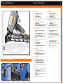
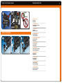
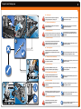
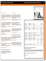
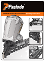
®
F250S PP Positive Placement Nailer Operating Instructions
3
Prepare for use | Check Contents
S
F250
iler
nt Na
ceme
la
ive P
PositPP
4
3
2
GB - Prepare for use:
FIN - Päivittäinen tarkistus:
1.
2.
3.
4.
1.
2.
3.
4.
Smooth safety yoke movement
Trigger Movement
Worn or cracked handle
All screws and bolts are tight
N - Daglig vedlikehold:
1.
2.
3.
4.
1.
2.
3.
4.
Leichtgängige Sicherheitsnase (WCE)
Schalterbewegung
Übermässig abgenutzter oder gebrochener Handgriff
Alle Schrauben und Bolzen müssen fest sein
P - Manutenção:
1.
2.
3.
4.
1.
2.
3.
4.
s’assurer que le palpeur de sécurité coulisse librement
vérifier que la gâchette soit libre
vérifier que la poignée de l’appareil ne présente pas de fissures ou d’usure importante.
vérifier que toutes les vis de l’appareil sont bien serrées
Desplazamiento del Seguro
Colocacion del Gatillo
Empuñadura excesivamente desgastada o agrietada
Ajuste de todos los tornillos y tuercas
NL - Dagelijks onderhoud:
1.
2.
3.
4.
Soepele werking van de veiligheidsbeugel
Trekker merchaniek
Uitzonderlijk versleten of gescheurd handvat
Alle schroeven en moeren zitten vast
DK - Daglig vedligehold:
1.
2.
3.
4.
Prepare for use | Compressor Pressure
02
03
Sikkerhetsbøylens bevegelse
Avtrekkerbevegelse
Ekstem slitasje eller sprekker i pistolhuset
Sitter alle skruer og bolter fast?
F - maintenance quotidienne:
1.
2.
3.
4.
1
Tarkista varmistimen liikkuvuus
Tarkista liipasimen liikkuvuus
Tarkista rungon kunto
Tarkista ruuvien ja pulttien kireys
D - Bitte überprüfen sie täglich:
E - Mantenimiento Diario:
01
5
Prepare for use | Daily Maintenance
Prepare for use | Daily Maintenance
Check sikring går let og ubesværet
Check aftrækker kan bevæges ubesværet
Check for slidtage eller revner i materialet
Alle skruer og bolte sidder fastspændt
S - Dagligt underhåll:
1.
2.
3.
4.
Säkerhetsbygeln ska fungera mjukt vid manöver
Kontrollera avtryckaren
Handtaget får inte vara överdrivet nedslitet eller ha sprickr
Kontrolla att alla skruvar och bultar är ordentligt fastskruvade
Movimento do sistema de segurança
Movimento do gatilho
Punho partido ou excessivamente gasto
Todos os parafusos e porcas estão apertados
I - Manutenzione quotidiana
1.
2.
3.
4.
Scorrimento agevole del meccanismo
Corretto movimento del grilletto
Buono stato dell’impugnatura (non troppo usurata o rotta)
Serraggio corretto di tutte le viti
Adjusting the depth of drive
Prepare for use | Compressor pressure
01
02
GB – Prepare for use
User settings
Depth control
D – Vor dem Gebrauch
Grundeinstellungen vornehmen
Tiefeneinstellung
F – mise en service
Installation
Réglage de profondeur
Adjusting the Depth Adjuster
01
E – Preparacion para el uso
Ajuste de la maquina
Control de profundidad
02
03
NL – voorbereidling ingebruikname
Gebruikersintellingen
diepte instelling
DK – Gør kiar til brug
Personlig indstilling
Dybde regulering
S – Före användning
Ställ in verktyget för användning
Kontrollera djupinställningen
FIN – Ennen käyttöä
Käyttöasetukset
Syvyyden säätö
N – Klargjør for bruk
Brukerinnstillinger
Innskytingsdybde
P – Preparar para utilizar
Colocar em posição
Controlar a profundidade
I – Preparazione all’uso
Regolazioni dell’utilizzatore
Controllo di profondità
7
9
Prepare for use | Clearing a jam
GB – Clearing a jam
01
02
03
Always disconnect from compresses air supply before
servicing, adjusting the tool, or clearing a jam.
Take tool out of service immediately and have it serviced by
an authorised service engineer.
D – Lösen eines verklemmten Nagels
Die Druckluftzufuhr vor Einstellung bzw. Reparatur des
Geräts stets unterbrechen.
Gerät sofort aus dem ziehen und nur von autorisiertem
Fachpersonal überprüfen lassen.
F – Recherche des pannes
Débrancher I’outil de son alimentation en air comprimé avant
toute opération de maintenance, de réglage ou de déblocage.
Ne travailler jamais avec un appareill défectueux. Si la
panne persiste envoyer votre appareil au service après
vente qualifié.
E – Desatascar la maquina
04
Desconecte siempre la herramienta del suministro de aire
comprimido, antes de llevar a cabo operaciones de
mantenimiento o ajuste, o de despejar un atasco.
Deje de utilizar la maquina inmediatamente y llevela a un
servicio tecnico autorizado.
NL – Een storing oplossen
Koppel altijd de aan voer van perslucht los voordat u
onderhoud gaat plegen, het apparaat afstelt of een storing
wegneemt.
Het apparaat onmiddellijk uit gebruik nemen en repararen
door een hiertoe gemachtigde service monteur.
DK – Hvordan fjerner man evt. Fastklemte
05
befæstelseselementer Afbryd altid trykluffen før justering
eller reparation af sømpistolen.
Tag værktøjet ud af brug omgående og hav det serviceret af
et autoriseret værksted
S – Rensa vid fastkörning
Avbryt alltid trycklufttillförseln innan du justerar eller utför reparationsarbete på spikningsverktygen.
Stäng av verktyget omedelbart och låt en auktoriserad
serviceman åtgärda felet.
FIN – Jumiutuneiden naulojen poistaminen
Irrota työkalu paineilmajärjestelmästä aina ennen huoltoa, työkalun säätöä tai tukoksen selvittämistä.
Poista naulain käytöstä välittömästi ja korjauta valtuutetussa huollossa.
N – Reparere en forkiling
06
07
08
Steng alltid av trykkluften før justering eller reparasjon av
stiftepistolen.
Ta verktyet ut bruk omgående og lever det inn til service
hos en godkjent service-mann.
P – Desempenar a máquina
Desligue sempre a a máquina do compressor de ar antes de
fazer a manutenção, ajustar a máquina ou desencravar um
prego.
Retire a máquina de serviço imediatamente e ponha-a ao
dispor de um engenheiro autorizado.
I - Eliminazione di un inceppamento
Prima di intervenire su di un attrezzo, ripararlo o eliminare un inceppamento, scollegare sempre la forte di aria compressa.
Interrompere immediatamente I’utilizzo dell’attrezzo e farlo
riparare presso un centro autorizzato.
Technical specification | Declaration of conformity
Technische Daten / Spécification Techniques / Technical Specifications
B
GB – Declaration of conformity
S – Konformitetsdeklaration
We declare that this product is in conformity with the following
standards or other normative documents. EN 292-1:1991; EN
22-2: 1995; EN349:1993; EN 792-13:2001 Following the provision
of EEC Directives
Deklarear att denna produkt ar I konformitet med följande
standard eller andra normativa dokument. EN 292-1:1991;
EN 22-2: 1995; EN349:1993; EN 792-13:2000 I enlighet med
föreskrifferna I EEC Direktiven
D – Konformitätserklärung
FIN – Vaatimuksenmukaisuusvakuutus
Wir erklären, dass dieses Produkt mit den folgenden Normen
oder normativen Dokumenten übereinstimmt. EN 292-1:1991;
EN 22-2: 1995; EN349:1993; EN 792-13:2000 Gemäß den
Bestimmungen der EWG
Vahvistaa, etta tama tutoe Paineilmanaulain on seuraavien
vaatimusten tai normidokumettien mukainen.
EN 292-1:1991; EN 22-2: 1995; EN349:1993; EN 792-13:2000
N – Samavarserkæring
F – Déclaration de conformité
Nous déclarons que ce produit est conforme aux normes ou
autres documents normatifs. EN 292-1:1991; EN 22-2: 1995;
EN349:1993; EN 792-13:2000 Conformément aux dispositions
des Directives du EEC
E – Declaration de conformidad
Vi erklærer at dette produkt samsvarer med følgende standarder
eller normer. EN 292-1:1991; EN 22-2: 1995; EN349:1993; EN 79213:2000 Som følger bestemmelser I EU-direktiv
P – Declaração de conformidade
Declaramos que este produto está em conformidad com as
seguintes normas standard ou outros documentos normativos.
Nosotros declaramos que este producto esta en comformidad
EN 292-1:1991; EN 22-2: 1995; EN349:1993; EN 792-13:2001
con los siguientes estandares u otras normas de documentación. Seguindo as directivas EEC
EN 292-1:1991; EN 22-2: 1995; EN349:1993; EN 792-13:2000
I – Dichiarzione de conformita
NL – Konformiteits verklaring
Noi dichiariamo che prodotto è conforme alle norme o ad altri
Wij verklaren dat dit produkt conform de volgende standaarden documenti normativi.EN 292-1:1991; EN 22-2: 1995; EN349:1993;
of andere norm stellingen is.
EN 792-13:2000 In conformita alle disposizioni delle Directive
EN 292-1:1991; EN 22-2: 1995; EN349:1993; EN 792-13:2000
DK – Overenstemmelseserklaering
A
D
F
UK
Dim
F250SS PP
Spezifikat.
Befestigmittel
Spécification des
moyens de fixation
Fastener
Specification
Ø
L
3.75 - 4.0mm
38 - 64mm
Geräte gewicht
Poids
Tool Weight
Abmessung
Spécification
Dimensions
A
B
C
4.0kg
Luftverbrauch
Consommation d’air
Air Consumption
2.9 litre @ 6 bar
Betriebsdruck
Pression d’opération
Operating Pressure
5 - 8 bar
Lade kapazität
Capacité du magasin
Load Capacity
Min - Max
370mm 130mm
450mm
44 - 48 nails
Schallpegel
Valeurs du bruit
Noise Level
LWA. 1s
LpA. 1s
LpA 1s1m
99.8 dB (A)
93.5 dB (A)
86.8 dB (A)
Vibrations-werte
a hwz
5.9m/s
Valeurs de vibration
Vibration Value
Normative Dokumente / Documents Normatifs / Normative Documents
EN 12549: 1999 / 2, EN ISO 8662 - 11: 1999
Erklærer herved, at produktet er I overensstemmelse med
nedenstaende normer eller normative dokumenter. EN 2921:1991; EN 22-2: 1995; EN349:1993; EN 792-13:2000 I henhold til
bestemmelserne I EU’s direktiv
C
ITW Paslode - van Heemskerckweg 5:5928 RB Venlo: The Netherlands
Erik Mul - Design
11
13
Ref No
Part No
Description
1
2
3
4
*5 *6 7
*8 9
10 11 12 13 14 15 16 17 18 19 21 22 23 24 25 27 28 31 29 30
32 33 34 35 36 37 38 39 40 41 42 43
44 501043
501752 501300 501017 500461 092042 500407 501001 406041 500455 401946 091208 401950 500456 500454 095432 500453 402906 092971 501061 402011 501283 500249 092235 501002 500866 501286 501333 501334 501219 501299 091622 501410 402669 501590 501241 402668 097748 097746 071297 092174 401958 1 T.H.S.C.S. 1/4 -20 x 1/2”
1 Air Deflector
4 S.H.C.S. 1/4-20 x 1-1/4”
1 Cap
1 O-Ring
2 O-Ring
1 Spring, Main Valve
1 Gasket, Cap
1 Retaining Ring
1 Upper Valve Piston
1 Seal, Main Valve
1 O-Ring
1 O-Ring
1 Lower Valve Piston
1 Post
1 O-Ring
1 Bumper, Post
1 B.H.S.C.S.10-32 x 5/8”
1 O-Ring, Piston
1 Driver Blade
1 Seal Sleeve
1 Sleeve, Machined
1 O- Ring
1 O-Ring, Sleeve
1 O-Ring
1 Bumper
1 Housing
1 Label, Housing-Left
1 Label, Housing -Right
1 End Plug, Housing
2 S.H.C.S. 1/4-20x 1”
1 Reducing Pipe Bushing
1 O-Ring
1 Pin, Trigger
1 Lever
1 Probe
1 Retaining Washer
1 Spring, Valve Pin
1 Valve Pin
3 Roll Pin 1/8 x 1-1/8”
1 O-Ring, Valve Body
1 Valve Body
Ref No
Part No
Description
45 46 47 48 49 50 51 52 53 54 55 56 57 58 59 60 61 62 63 64 65 66 67 68 69 70 71 72 20 74 75 76 77
78 79 80 501039 502480 095417 009016 501006 500849 404800 500850 501409 500717 500902 500783 501770 501771 500848 501046 500513 501500 501567 500509 501028 501360 066840 404414 404325 500520 500458 501137 500899 091618 501654 500525 500779 501336 501136 501480 1 Sequential Trigger Assembly
1 Nose
4 Lockwasher 5/16
4 S.H.C.S. 5/16-18 x 1”
1 Spring, W.C.E.
1 Upper W.C.E.
1 Washer, W.C.E.
1 Lower W.C.E.
1 Probe Pin
1 Nail Cover
1 Follower
1 3/16 Hex Key, Short Arm
1 End Cap, Magazine-LF
1 End Cap, Magazine-RT
1 Latch
1 Drum Pin Assembly
1 Negator Assembly
1 Spring, Lever
2 Screw 1/4-28 x 3/4”
1 Front Bracket
1 Spring, Latch
1 Shoulder Screw #8
1 S.H.C.S. 8-32 x 3/4”
2 Flatwasher #8
3 Stop Nut
2 Wear Strip
1 Warning Label
1 Logo Label
1 Piston
1 S.H.C.S. 1/4-20 x 1/2”
1 Magazine w/ Wear Strips
1 5/ 16”-24, Lock Nut 1 Washer
1 Flange
1 Shoulder Screw
1 Name plate
1 Faste ner Useage Label
79
80
1126/395740/2009/1