1
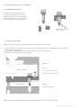
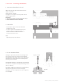
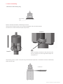
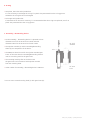
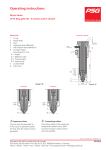
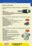
Operating instructions
Micro-Series
2016 Front, Ring gate RX - A-version and H-version with heater replacement at the front
Stock List:
A-Version signed
1
2
3
4
5
6
O-ring
Nozzle body
Case
Alignment dowel Ø2m6x8
Anti-rotation dowel Ø4m6x10
Compact heater,
consisting of 6.1-6.4
6.1 Heater
6.2 Reflection tube
6.3 Thermocouple
6.4 Locking ring
7 Location head
8 Gate insert
drawn out
of position!
flexible
cable outlet
Detail "A"
A-Version
Important Note:
The tool must be grounded!
If the nozzle is operated outside
the tool, then the nozzle must be
grounded.
H-Version
Detail "A"
Connecting cables:
Connecting cables of the nozzles are
temperature resistant up to 200°C
and must not get in direct contact
with the manifold.
bedien_micro_2016_RX_A+H_Front_032014e - 1/8
We reserve the right to make technical changes
PSG Plastic Service GmbH • P.O. Box 42 01 62 • 68280 Mannheim • Germany
Phone +49 621 7162-0 • Fax +49 621 7162-162 • www.psg-online.de • [email protected]
03/2014
1. Installation Micro-nozzle - as supplied
1.1 Installation Micro-nozzle
Install the nozzle body (2) with case
(3) and compact heater in the nozzle
absorption plate. First insert the heater
cables from above in the cut out of the
tool. Anti-rotation (5) must be located.
Bending cable outlet see
point 5, step 4.
1.2 Assembly as "Hot Half"
Note: Insert the O-rings (1) into the groove of the nozzle flange before assembly.
•The installation of the manifold can be made, after the height adjustment has already being made following
instructions according to PSG.
(See datasheet "Assembling instruction for standardized hot runner manifolds.")
•Centring pin and dowel pin must be installed.
Manifold
O-ring (1)
Dowel pin (manifold)
Anti-rotation dowel (nozzle)
Anti-rotation dowel (manifold)
Plate guidance
Mold plate
Ante-chamber sealing
Note: Plate guidance must work before immersing the nozzle into the ante-chamber sealing.
bedien_micro_2016_RX_A+H_Front_032014e - 2/8
2. Gate insert - dismantling (RX3/RX4/RX5)
2.1 Gate insert-dismantling in the tool
While changing the gate insert leave the micro
nozzle in the tool.
Heater remains installed.
To begin the cavity-plate must be pulled-down to
reach the gate inserts.
Important:
1. Hot runner system must be cold (max. 40°C).
2. Anti-rotation dowel must be fitted.
2.1a Procedure
- To remove the gate variants RX5 dismantle
the gate insert cold.
- In case of gate variant RX3/RX4 heat up the
nozzle to 400°C and than dismantle.
For all 2 variants the width across flats of
the centring head is 9 mm.
Note:
Tightening torques see table 3.1.
2.1.b Gate RX3/RX4 and RX5:
Usually the gate insert sticks in the centering head.
Then clamp carefully the centering head together
with the gate insert at key area in a vice and remove
the gate insert carefully out of the centering head
with an ejection mandrel.
Ejection mandrel
The ejection mandrel can be self made, or purchased
from PSG as a complete assembly/dismantling- device.
(Art.no. 298410)
Data about Angles are important for manufacturing,
otherwise the gate insert could be damaged.
The depth of 4 mm is important so that the gate tip
isn’t damaged.
Key area
bedien_micro_2016_RX_A+H_Front_032014e - 3/8
2.2 Gate insert-replacement outside the tool
Note:
Only dismantle the nozzle if the heater was removed
before, see point 4 „heater replacement“.
It is easier to clamp the uninstalled nozzle at the spanner
flat of the body in a vice (use soft jaws) and to change the
gate insert with a 9 mm key or a ring key.
Important: Dismantle the gate inserts RX5 always
in cold condition. Dismantle the gate insert RX3/RX4
only in the tool or with installed heater to heat up the
nozzle.
Assembly-/
dismantling-device
Unscrew
centring head
Unscrew
centring head
Than see procedure 2.1.a und 2.1.b.
3. Gate insert installation
We recommend to assemble the gate insert only when the nozzle is already installed. The heater should be assembled.
This means especially the gate insert type RX3/RX4, when it is needed to heat the nozzle up 400°C (see point 3.1).
Note, that the sealing surfaces are free from plastic.
Example: RX-gate:
Step 1: Assemble the gate insert (8) in the centering head (7).
Step 2: Now both are screwed together into the nozzle body (2).
Sealing surfaces
Finally, tighten up to the recommended torque, see table 3.1.
Note the temperature!
bedien_micro_2016_RX_A+H_Front_032014e - 4/8
3.1 Tightening torques for the 2016 gate insert types
Gate insert
Torque
Spanner opening
RX5
8 Nm (nozzle cold)
SW 9
RX3/RX4
15 Nm cold tighten and then to
400°C heat and with 15 Nm
pull tight again!
Important!
SW 9
4. Heater installation in the tool
View on the nozzle
The heater must easily be slided on the nozzle body.
Turn heater outlet into the direction of the cut out
before assembling the heater.
Cut out
Step 1:
Step 2:
Slide the compact heater (6) over the nozzle body (2).
Bend the cable outlet lightly (about 5 mm), then bring the
ring thermocouple over the location head.
approx. 20°.
bedien_micro_2016_RX_A+H_Front_032014e - 5/8
Step 3:
Step 4:
The heater slides on the nozzle body easily.
Push the ring thermocouple (6.3) carefully on the nozzle
body (2).
Always keep a distance of approx. 1.5 mm between
heater (6.1) and ring thermocouple (6.3).
At the same time push forward the heater (6.1).
A assembly/dismantling sleeve can be used to slide on
the ring thermocouple (6.3).
If the compact heater (6) is assembled, the heater outlet
must be completely tiered down.
Do not go under a bending radius of 3 mm.
Easily bends by hand.
Note:
The compact heater must seat down on the nozzle
body.
Fixed seat
Firm seat must be ensured.
min. bending radius 3mm
The shown assembly/dismantling sleeve case can be manufactured by the customer, or can be bought from
PSG as a complete unit.
Put the assembly/dismantling sleeve on the
ring thermocouple (6.3) and press the
ring thermocouple (6.3) carefully on the front
of the nozzle body (by hand) while pushing
down the heater (6.1) at the same time.
Assembly/
Dismantling sleeve
- Semi-locking ring is to assemble.
We recommend to use the new.
(Spare part-heater inclusive)
Locking ring
bedien_micro_2016_RX_A+H_Front_032014e - 6/8
5. Heater dismantling
- Remove the semi-locking ring.
Semi-locking
ring
Remove mould plate before assembling the heater.
After that the compact heater can be removed together with the thermocouple.
Use extractor to remove thermocouple (see picture).
Detail X
Detail X
Note:
Push the heater push down at the same time and
be very carefully, since the ring thermocouple can
easily break of.
Alternatively, press up (don´t lever) the ring at the thermocouple with a screwdriver from the nozzle body
gently step by step.
Screwdriver
bedien_micro_2016_RX_A+H_Front_032014e - 7/8
6. O-Ring
•Test phase, short-time serial production:
It is not necessary to exchange the o-ring if no plastic has penetrated into the O-ring groove.
Otherwise the o-ring has to be exchanged!
•For longer serial production:
If maintenance for the tool is necessary, it is recommended that the o-rings are replaced, even if no
plastic has penetrated into the o-ring groove.
7. Assembly- / Dismantling device
•For the assembly -, dismantling device it is planned to have
diameter 21mm for the 2016 micro nozzle and with
diameter 24mm for the 2016 micro frontal nozzle.
for 2016
Standard
•The ejection mandrel (a) and the assembly/dismantling
sleeve (b) are components of the device.
•The M8x0,75 thread is used for the ejection mandrel gate
insert. At the same time the assembly/dismantling sleeve is
used as a receiving tank for the gate insert.
•The centering head lays flat on the device and
the gate insert can be removed with ejection mandrel
from the centering head.
•Order number for assembly-, dismantling device is 298 410.
for 2016
Front
* You can see a screwed centring head (7) with gate insert (8).
bedien_micro_2016_RX_A+H_Front_032014e - 8/8