1
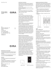
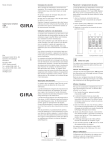
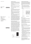
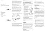
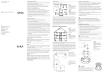
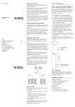
Operating Instructions Safety instructions Inserting/replacing batteries Observe the notes on power supply. No other form of power supply other than specified in these instructions may be used. The sensor unit is supplied with voltage via the transmitting unit. This is operated with four alkaline batteries (1.5 V, type LR06, Mignon, AA). Both sides of the transmitting unit have small indentations to open the battery compartment. Conventional batteries must never be charged. Danger of explosion! Do not throw batteries into fire! Do not short-circuit batteries! Electricity meter sensor 2356 02 1. Insert a screwdriver into the indentations and pull off the battery compartment cover. Only operate device indoors and avoid influence of humidity, dust, sun and heat. 2. Insert four LR06 batteries with correct polarisation into the transmitting unit. Proper use 3. Replace the battery compartment cover and snap in. The Gira electricity meter sensor is for measurement of electricity consumption data with threephase current meters and single phase meters with a rotating disk with red marking (Ferraris disk). Uses other than those specified in these operating instructions are not in accordance with the intended purpose and lead to exclusion of warranty and liability. This is also the case with modifications and conversions. The values measured are not suitable for purposes of public information. The device is intended solely for private use and not for invoicing. Phone +49 (0) 2195 / 602 – 0 Fax +49 (0) 2195 / 602 – 339 Functional description Gira Giersiepen GmbH & Co. KG Electrical Installation Systems 06/11 P.O. Box 1220 42461 Radevormwald The main meter is usually sealed and is the property of the power supply company. Modifications are prohibited. If measurement devices are installed, these must not influence the meter and must be removable without trace. The electricity meter sensor is designed to fulfill these requirements. No modifications to the meter or mains supply are required due to contactless, optoelectronic determination of measurement data. www.gira.com [email protected] The electricity meter sensor may be operated in all EU and EFTA countries. i Battery compartment Using batteries The electricity meter sensor may only be operated with alkaline batteries. Rechargeable batteries must not be used. "Empty battery" display The Gira electricity meter sensor consists of a sensor unit and a transmitting unit. The sensor unit registers the passing through of the red marking on the rotating disk (Ferraris disk) and passes the measurement data on to the transmitting unit. This transmits the data to the Gira energy and weather display. The sensor unit and transmitting unit each have an LED. The LED of the sensor unit lights up when the red marking of the Ferraris disk is registered. The LED of the transmitting unit lights up when a radio transmission occurs. In normal operation, after pressing a button the display of the transmitting unit shows the mean power during the last Ferraris disk rotation for a period of three minutes. Declaration of Conformity Side view The sensor unit and transmitting unit are accommodated in separate housings for optimal positioning. In this way the sensor unit can be positioned directly at the electricity meter and the transmitter unit can be positioned at a location with good radio reception with the aid of a connection cable. The declaration of conformity can be downloaded at www.download.gira.de. Warranty With empty batteries, bAt appears (alternating with the normal display) in the display of the transmitting unit. If this is the case, replace the station's batteries. The assignment to the energy and weather display is maintained when replacing the battery. Assigning the transmitter Radio components must be assigned to each other to enable communication. 1. Press and hold for 3 seconds at the transmitting unit. ✓ The transmitting unit now transmits an assignment signal every five seconds for the next five minutes. The LED of the transmitting unit lights up for the duration of this assignment procedure. 2. Trigger the programming mode on the energy and weather display within these five minutes (see operating instructions for the energy and weather display). ✓ After start-up the transmitting unit displays the version number as well as an A and a kW for 1 second. This signalises that the sensor has been assigned. ✓ Following successful assignment the energy and weather display then displays the electricity meter data. We provide a warranty in accordance with the statutory requirements. 3. Pressing again exits the programming mode of the sensor. Please send the device postage paid with error description via the specialist trade to our central customer service centre. A sensor can be assigned to any number of energy and weather displays. Gira Giersiepen GmbH & Co. KG Service Center Dahlienstraße 12 42477 Radevormwald Sensor unit Transmitting unit Deleting the assignment Deletion of the electricity meter sensor assignment is only possible at the energy and weather display. Installation Setting the scanning sensitivity Mounting the sensor unit i Work precisely! The sensor unit must be positioned precisely above the meter disk. Incorrect positioning of just a few millimetres may cause malfunctioning. This is why the following work steps must be carried out very precisely. Use the included template for correct mounting of the sensor unit. Marking holes Adaptation of the sensor unit to the Ferraris disk may be necessary because of the mechanical differences between the meters installed by various power supply companies. Scanning sensitivity can be adjusted for this purpose. With correct scanning sensitivity, each passing through of the red marking of the Ferraris disk is displayed on the sensor unit via the LED. If the marking is not or only partly detected, scanning sensitivity can be adjusted as follows: 1. Switch on a major consumer device of at least 3000 W power consumption (e.g. a cooker) so that the Ferraris disk rotates sufficiently. 2. Press Mode briefly ✓ The currently set threshold between -99% and +99% is shown. Positioning cross 1. Clean or degrease the meter disk with a suitable cleaning agent. 2. Place the template onto the front panel of the meter so that the red marking of the meter disk runs straight and centrally through the positioning cross of the template. 3. In this position, draw marking points in the middle of the four marking holes with a suitable pen. 4. Stick the sensor unit onto the meter disk with the aid of the power strips. The positions of the four markings on the meter disk must correspond to the four bridges of the sensor unit. i Caution do not press in the front panel! Do not apply excessive pressure to the front panel of the meter when affixing the sensor unit. Power strips 3. Modify the scanning sensitivity with so that the control LED on the sensor unit lights up permanently. 4. Modify the scanning sensitivity with until each passing through of the red marking is correctly detected. Note the value. 5. Modify the scanning sensitivity with until the LED no longer lights up when the red marking of the rotating disk passes the detection range of the sensor unit. Note the second value. 6. Set the average value of both noted values via and . No signalling is output after this to protect the service life of the batteries. To activate triggering of the LEDs for 10 minutes, briefly press any button of the transmitting unit. Transmission behaviour and radio interference The transmitting unit transmits data at periods of 2 – 3 minutes to the energy and weather display. Radio transmission occurs on a non-exclusive transmission path, and interference cannot be excluded for this reason. For further information please consult the energy and weather display operating instructions. In order to manually restore synchronisation, the assignment of the transmitting unit to the energy and weather display can be deleted and reassigned, as specified in the "Assigning the transmitter" section. Maintenance and cleaning The product is maintenance-free apart from battery replacement. Leave repair to a qualified expert. Clean the product with a clean, soft, dry and lintfree cloth. The cloth may be dampened with luke-warm water for removal of heavier soiling. Do not use solvent-based cleaning materials. The plastic housing and inscription may be adversely affected. Waste disposal information Example: 1st value: +20, 2nd value: +40, Scanning sensitivity: +30 Remove empty batteries immediately and dispose of them in an environmentally-friendly way. Do not throw batteries into the domestic refuse. Local authorities inform about environmentally-compatible disposal. The end consumer is legally required to return used batteries in accordance with legislative requirements. 7. Press Mode to save the value and return to normal operation. ✓ If no button is pressed for longer than 60 seconds the device automatically returns to normal operation. The set scanning sensitivity is saved in this case. Setting the meter constant Bridges Mounting the transmitting unit 1. Connect the transmitting unit to the sensor unit with the connection cable. 2. Test whether the energy and weather display is receiving data regularly from the transmitting unit. If necessary, modify the position of the transmitting unit or energy and weather display to establish good radio communication. For wall mounting, use the two keyholes on the rear. For correct measurements, the meter constant specified on the meter must be set. The meter constant specifies how many rotations the rotating disk (Ferraris disk) does for energy consumption of 1 kWh. The meter constant is usually printed on the meter. If not, the value can be obtained from your power supply company. Technical data 1. Press and hold Mode for more than 2 seconds. ✓ The display shows the currently set meter constant in r/kWh and the LED of the transmitting unit lights up. 2. Set the required meter constant with and . Counting up and down is accelerated if the buttons are pressed and held longer than 2 seconds. 3. Press Mode to save the value and return to normal operation. 7,9 cm 1. Mark the drilling holes. 2. Drill the mounting holes (Ø 5 mm) and insert the included dowels. 3. Fasten the included screws. These must protrude by approx. 0.5 cm for the transmitting unit to be hung on. ✓ If no button is pressed for longer than 60 seconds the device automatically returns to normal operation. The set meter constant is saved in this case. ✓ The LED of the sensor unit displays the running through of the Ferraris disk until ten minutes after the last pressing of a button, and the LED of the transmitting unit displays each transmission sequence by intermittently lighting up. ✓ For the next 3 minutes, electricity consumption between the last two pulses is displayed in W. Power supply: 6V Batteries: 4 x alkaline 1.5 V (LR06, Mignon, AA) Do not use rechargeable batteries! Current consumption: approx. 140 μA Scanning sensitivity: -99 to +99% Meter constant (can be set): 10 to 2500 r/kWh Transmission interval: 2 to 3 minutes (dynamic) Transmission frequency: 868.35 MHz Free field range: 100 m Ambient temperature: 0 to 50 °C Dimensions (W x H x D) Transmitting unit: Sensor unit: 68 x 105 x 30 mm 40 x 30 x 14 mm i Note The manufacturer or seller of this electricity meter sensor accepts no responsibility for incorrect values and any consequences that may ensue.