1
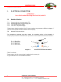
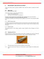
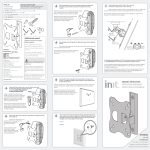
FRANKFURT LASER COMPANY MLT-Laser Diode Module OPERATING INSTRUCTIONS 1 FRANKFURT LASER COMPANY An den 30 Morgen 13, 61381 Friedrichsdorf, Germany Tel.: +49(0)6172.27978-0 Fax: +49(0)6172.27978-10 E-mail: [email protected]; Internet: WWW.FRLASERCO.COM FRANKFURT LASER COMPANY Contents 1. FOREWORD ..................................................................................................... 3 2. INSPECTION ..................................................................................................... 3 3. INSTALLATION ................................................................................................ 3 4. WORKING INSTRUCTIONS ............................................................................. 4 4.1 Safety precautions while operating the product ........................................................................... 4 4.2 Installation ..................................................................................................................................... 4 4.3 Heatsinking ................................................................................................................................... 4 4.3 Laser module operation requirements .......................................................................................... 4 5. ELECTRICAL CONNECTION ........................................................................... 5 5.1 Module with wires ......................................................................................................................... 5 5.2 Module with connector .................................................................................................................. 5 6. ADJUSTING THE OPTICAL OUTPUT ............................................................. 6 6.1 Optic type ...................................................................................................................................... 6 6.1.1 Without forming optics ........................................................................................................... 6 6.1.2 With forming optics ................................................................................................................ 6 6.1.3 Special optics ........................................................................................................................ 6 6.2 Adjusting the lens ......................................................................................................................... 6 7. MAINTENANCE AND REPAIR ......................................................................... 7 8. GUARANTEE .................................................................................................... 7 9. MODULE DRAWINGS ...................................................................................... 8 9.1 MLT ............................................................................................................................................... 8 10. ACCESSORIES ................................................................................................ 9 10.1 Wall Plug Power Supply ............................................................................................................ 9 10.2 Laser Diode Module Mount ....................................................................................................... 9 2 FRANKFURT LASER COMPANY An den 30 Morgen 13, 61381 Friedrichsdorf, Germany Tel.: +49(0)6172.27978-0 Fax: +49(0)6172.27978-10 E-mail: [email protected]; Internet: WWW.FRLASERCO.COM FRANKFURT LASER COMPANY 1. FOREWORD Dear Customer, Thank you for buying a Frankfurt Laser Company laser diode module. It was developed on the basis of the latest achievements in science and technology and produced using state-ofthe-art components. Since laser modules are designed to be used as components for installation into an OEM product, no provisions were or could be made to provide the laser safety which would normally be required of your application and equipment into which they will be installed. By accepting delivery of this device, you accept responsibility to insure all necessary precautions will be taken with regards to laser safety in your application. Please, use the laser diode module with the purpose it is designed for and in accordance with the instructions provided. Improper or unauthorized use of this device will void the guarantee. The vendor will not be liable for the consequences of any incorrect or unsafe use of the laser diode module. 2. INSPECTION Before using the laser diode module for the fist time, please: Make sure the packing is undamaged Make sure the laser diode module shows no visible signs of damage In the event of any damage, please, notify the vendor immediately. Retain the original packing material to return damaged goods and use foam packaging for cushioning where appropriate. 3. INSTALLATION Before installing the laser diode module into the set-up, make sure that: The serial number of the product corresponds to the number in the packing list The supply voltage and laser diode module control signals correspond to those set by yourself ATTENTION! Laser diode module housing has electrical potential 3 FRANKFURT LASER COMPANY An den 30 Morgen 13, 61381 Friedrichsdorf, Germany Tel.: +49(0)6172.27978-0 Fax: +49(0)6172.27978-10 E-mail: [email protected]; Internet: WWW.FRLASERCO.COM FRANKFURT LASER COMPANY 4. WORKING INSTRUCTIONS 4.1 Safety precautions while operating the product The laser diode mounted in the module is able to create radiation, the appropriate safety precautions applicable in your country to this eye safety laser class must be observed. 4.2 Installation It is strictly prohibited to apply mechanical force to the laser diode module housing while it is used or installed in the set-up. It can lead to instantaneous damage of laser diode and optical system. 4.3 Heatsinking To ensure correct operation of the laser diode module it may be necessary to heat sink the module. Modules that have an output power of 5mW or less do not require special heat sinking. All other modules require heat sinking to remove waste heat from the module which will improve the stability characteristics and increase the lifetime. For better heat dissipation from the laser diode module use aluminum or copper holders to remove heat energy, do not place excessive force on the modules, this may cause internal damage. 4.3 Laser module operation requirements Electrical signals should comply with the specification of the laser diode module. It is strictly prohibited to expose the optical surfaces of the module to hard particles of any size, as it can damage optical coatings and integrity of optical parts. 4 FRANKFURT LASER COMPANY An den 30 Morgen 13, 61381 Friedrichsdorf, Germany Tel.: +49(0)6172.27978-0 Fax: +49(0)6172.27978-10 E-mail: [email protected]; Internet: WWW.FRLASERCO.COM FRANKFURT LASER COMPANY 5. ELECTRICAL CONNECTION ATTENTION! Laser diode module housing has electrical potential 5.1 Module with wires 5.1.1 5.1.2 5.1.3 5.1.4 Connect red wire to power supply: 5V* Connect black wire to power supply: 0V Turn “ON” the power supply Turn “OFF” the power supply *Please insure that the module is for 5V some versions may operate at different voltages, if you are unsure please contact Frankfurt Laser Company. 5.2 Module with connector For convenience customer may also choose the connector option, in the interests of simplicity the pins will be referred to with equivalence to the module with wires and therefore Key Pin 1 = Black Wire Pin 2 = White Wire Pin 3 = Blue Wire Pin 4 = Brown Wire 2 3 1 4 Diagram shows the connector mounted to the module Cable is enclosed. Please ensure that the correct signal is applied to the correct pin. Any pins that are not in use should be isolated. 5 FRANKFURT LASER COMPANY An den 30 Morgen 13, 61381 Friedrichsdorf, Germany Tel.: +49(0)6172.27978-0 Fax: +49(0)6172.27978-10 E-mail: [email protected]; Internet: WWW.FRLASERCO.COM FRANKFURT LASER COMPANY 6. ADJUSTING THE OPTICAL OUTPUT There are several options currently available; these impact the ability to adjust the optical output; 6.1 Optic type 6.1.1 Without forming optics This module contains a single lens that will either Create a quasi-parallel beam Generate a focused spot at a set distance The optic can be supplied fixed or adjustable and is specified at the point of purchase. If the lens is fixed, there is no ability to change the beam spot. If the lens is moveable, the beam spot can be altered by moving the lens along the optical axis. 6.1.2 With forming optics In addition to the lens of the optical system there may also be other optical elements within the module that allow the user to change the spot shape and also the focus distance of the laser spot. 6.1.3 Special optics The optical system is fully custom, please contact Frankfurt Laser Company for further details. 6.2 Adjusting the lens Where that ability to change the focus point of the laser is available the custom key that was supplied with the laser diode module should be used to make the necessary change. Laser Diode Module Optic Adjustment Key The narrow part of the key is used to adjust the internal optics 6.2.1 Insert the narrow end of the key into the module, rotate to adjust to the desired spot size. 6 FRANKFURT LASER COMPANY An den 30 Morgen 13, 61381 Friedrichsdorf, Germany Tel.: +49(0)6172.27978-0 Fax: +49(0)6172.27978-10 E-mail: [email protected]; Internet: WWW.FRLASERCO.COM FRANKFURT LASER COMPANY 7. MAINTENANCE AND REPAIR The laser diode module does not require any special maintenance. The optical window can be cleaned occasionally with a soft cloth or using air flow. In case of failure, do not attempt to repair the product yourself! Please, return the product to the vendor immediately. 8. GUARANTEE Guarantee period is 12 months from the day the module is delivered. The guarantee is void, if the laser module: was used not in accordance with manufacturer’s instruction manual dissembled, regulated without manufacturer’s written consent was exposed to aggressive environment (liquids, rough dust) does not have the serial number 7 FRANKFURT LASER COMPANY An den 30 Morgen 13, 61381 Friedrichsdorf, Germany Tel.: +49(0)6172.27978-0 Fax: +49(0)6172.27978-10 E-mail: [email protected]; Internet: WWW.FRLASERCO.COM FRANKFURT LASER COMPANY 9. MODULE DRAWINGS 9.1 MLT Dimensions in mm Tolerances ± 0.2mm 8 FRANKFURT LASER COMPANY An den 30 Morgen 13, 61381 Friedrichsdorf, Germany Tel.: +49(0)6172.27978-0 Fax: +49(0)6172.27978-10 E-mail: [email protected]; Internet: WWW.FRLASERCO.COM FRANKFURT LASER COMPANY 10. ACCESSORIES The following accessories are also available for the laser diode module 10.1 Wall Plug Power Supply For those that wish to use a standard voltage socket to power the module we are able to offer the appropriate power supply, please contact Frankfurt Laser Company for further details 10.2 Laser Diode Module Mount The following mount is available to hold the laser diode module is position, the mount also allows easy adjustment. 9 FRANKFURT LASER COMPANY An den 30 Morgen 13, 61381 Friedrichsdorf, Germany Tel.: +49(0)6172.27978-0 Fax: +49(0)6172.27978-10 E-mail: [email protected]; Internet: WWW.FRLASERCO.COM