1
Operating Instructions
for the S - SW 3 Capacitive Threshold Switch
Unicontrol Electronic GmbH, 23 May 2000
1. Function
The capacitive threshold switch S-SW 3 is typically used for roller conveyor
control applications in rolling mills, in sandblasting plants, or the like. This switch
detects and evaluates the presence of metal parts and other conductive objects
within its sensing range. Contamination of the electrodes which may be caused by
slag, metal dust or a thin layer of abrasives will not affect the proper function of the
capacitive threshold switch.
The device consists of two parts:
- Sensor unit, housed in a plastic casing and a
- Sensor electrode
The sensor electrode is not included in the unit of supplied. It is dimensioned by the
user, based on the specific requirements of the application at hand. The shape of
the electrode determines the sensing range.
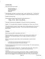
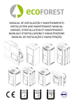
2. Sensor Unit
The sensor unit part is housed in a IP65 / DIN 40050 Makrolon casing. Two cable
inlets are available for making the electrical connections.
PG 9
PG 7
: 24V DC or AC voltage supply and relay output
: connection to sensor plate (coaxial cable)
The voltage supply and the relay output are applied to the two 3-pole plug-type
terminals, X1 and X2:
X1/ 1 and 2 : 24V (+/-10%)
X1/ 3
: reference potential ( machine casing or PE conductor)
X2
: floating NO contact (changeover contact, max. 230 V / 4 A)
If an inductive consumer is to be connected to X2, proper interference
suppression is required!
Connect the cable for the sensor plate to the 2-pole sensor terminal.
Use an RG58 ( 50 ohms ) coaxial cable or similar (mandatory).
Connect the cable core to the left terminal (X3/1), and the cable screen to the right
terminal (X3/2), as shown in the drawing.
Page 1/4
S-SW 3.tmd
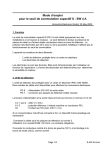
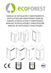
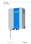
3. Sensor Plate
The sensor plate must include:
Sensing electrode A
Counter-electrode B
Mounting carrier C
Spacer D
The electrodes are made of conductive metal ( steel, aluminum, etc. ). The thickness
("d") of the material is non-critical and is adjusted to match the dimensions required.
Possible dimensions are:
Sensing electrode and counter-electrode ( same dimensions ):
Width "a": min. 30 mm, max. 200 mm
Length "b": min. 30 mm, max. 4000 mm
The type of mounting carrier depends on the type of mounting or application.
Spacer " D " is a plastic bolt as indicated in the drawing (min. 20 mm, max. 50 mm).
The sensor plate is mounted in such a way that the sensing electrode is as close to
the objects to be detected as possible. This ensures safe and reliable switching
performance.
4. Startup
Mount the sensor plate as described under Item 3.
Mount the electronics equipment so that the sensor cable (coaxial cable) is not
longer than 70 cm (standard cable, 50 cm in length; included in the scope of
supplies).
Before connecting the coaxial cable, check the electrodes to make sure that
there is :
1) No short-circuit present between the electrodes, and
2) No electrical connection to the machine frame.
Connect the screen of the coaxial cable to counter -electrode " B " and the cable core
to sensing electrode " A ".
At first, apply the supply voltage to X1. The green LED must go ON. After a brief
transient time of about one minute, carry out the calibrated as follows:
1st case:
The red LED is ON! Turn the setting potentiometer “GAIN” in the MINUS direction
(see symbol on the printed-circuit board) until the red LED goes OFF and the relay
drops out. Now slowly turn the potentiometer back a little. This is the point where
Page 2/4
S-SW 3.tmd
the level of sensitivity is the highest. The calibration procedure is completed!
2nd case:
The red LED is OFF! Turn the setting potentiometer “GAIN” in the PLUS direction
(see symbol on the printed-circuit board) until the red LED goes ON and the relay
picks up. Now slowly turn the potentiometer back a little until the LED goes OFF
again and the relay drops out. The calibration procedure is completed!
Follow this procedure to set the optimum level of sensitivity for the application at
hand.
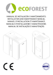
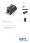
5. Parameter Setting
Use the SW1 dip switch on the printed-circuit board for setting the parameters. You
can set 3 parameters.
a) Switching hysteresis (Hyst.)
b) Switching delay (Delay)
c) Sensor plate size (Sens. size)
See drawing on the right for setting the
parameters.
6. Technical Data
Voltage supply
: 24V DC +/- 10 %, 24VAC +/-10% 50 Hz
Power consumption : approx. 2.3 VA
Output
: floating relay contact (changeover contact)
max. 230 V / 4 A ( fuse externally )
Temperature range : within -20° and 55° C
Dimensions
: 160 x 80 x 55 mm ( LxWxH )
Casing
: Makrolon, IP65 / DIN 40050, RAL 7035
7. Other Relevant Details
Installation and adjustment shall be carried out by qualified personnel only. Do not
operate the switch, unless the plastic cover is closed.
Our guarantee does not cover malfunctions due to faulty installation or manipulation
at the coil cores on the p.c.b.
UNICONTROL Electronic GmbH
Mannheim 23 May 2000
Page 3/4
S-SW 3.tmd
Spacer
Spacer
Page 4/4
S-SW 3