1
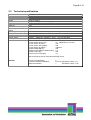
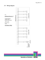
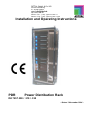
RITTAL GmbH & Co. KG Auf dem Stützelberg D – 35745 Herborn eMail: [email protected] http://www.rittal.de Service -Tel. : (+49) - (0)2772 / 505 - 0 Service - Fax : (+49) - (0)2772 / 505 - 2319 Installation and Operating Instructions PDR Power Distribution Rack DK 7857.300 / .310 / .330 - Status 3 November 2004 - Page 2 of 19 We reserve all rights in this technical documentation. Without our previous consent it must neither be multiplied nor made available for third parties. Neither must it be abusively utilised any other way by the receiver or third parties. Any violation of the above obliges the violating party to pay compensation and may lead to penal action. Contents 0. 1. 2. 3. 3.1 3.2 3.3 4. 4.1 4.2 5. 5.1 5.1.1 5.2 6. 7. 8. 9. 10. 11. Introduction Safety advice Demands on personnel engaged in installation and operation PDR Power Distribution Rack Configuration of PDR Scope of supply Technical specifications Functions PDR Wiring diagram Installation Installation PDR Connection power supply Features to be observed Commissioning Operation Maintenance Cleaning Disposal Service and service address FRIEDHELM L O H GROUP Page 3 of 19 0. Introduction The stable flow of information and production is the ‘lifeline’ of an enterprise. Loss of data, failure of function and production are causing extensive and in many cases life-threatening damage. Therefore, it is the declared company objective to ensure a maximum of safety and reliability. RITTAL is offering the support to achieve this: By means of universal competence in effective prevention, comprehensive safety, and centralised organisation, i.e. teamwork for IT safety and reliability! This results in optimum combination of power management and administration, enclosure monitoring, server administration and climate control components. The solution for power management is RITTAL PDR and PDM. This concept includes complete power distribution of the enclosure, i.e. power supply, distribution and protection. The system is made complete by its sophisticated modular structure. Basic installation can be implemented in next to no time. When the demands on the system increase expansion is easy by means of Power Distribution Modules (PDM). Power Distribution Rack (PDR) and Power Distribution Module (PDM) provide a revolutionary energy management for IT racks. The modular power supply system allows for energy supply from the 250A infeed through up to 8 plug-in Power Distribution Modules (PDM). The PDR is destined exclusively for operation in the data centre. The significant features of the RITTAL PDR are: • • • • • TS 8 rack measuring 800 mm wide, 2000 mm high, and 500 mm deep TS 8 rack alternatively 1200 mm high Distribution of 3 phases of 250A each through up to 8 PDM Adaptation to rising demands by simply plugging-in of up to 8 PDM Power circuit breaker 250V for protection and switching off the power supply The significant features of the RITTAL PDM are: • • • • Rack-mounted in 3 U sheet steel enclosure Distribution of 3 phases per 16A via 4 plug-in outlets Each phase and outlet individually fused All connections pluggable Page 4 of 19 1. Safety advice General notes The installation and operating instructions contain basic information for installing, putting into operation, and operating the RITTAL PDR. It is a must to make the instructions available to the installation technician and the administrative operating personnel and that they should read these carefully. RITTAL cannot accept liability for personal injury and material damage resulting from non-observance of the safety advice in the installation and operating instructions. It is essential to observe not only the general safety advice given in this chapter, but also the special safety advice given in the other chapters. Rittal CMC-TC Personnel qualification and authorisation Operation and any changes may be carried out only by authorised specialist personnel or by authorised trained operating personnel. Risks due to non-observance of safety advice Non-observance of the safety advice may result in risks for the personnel, as well as to the RITTAL PDR together with the connected equipment. Non-observance of the safety advice leads to the loss of the right to claim for any and all damages. ! # ϑmin ϑmax à IPxx Working on the PDR The generally applicable electrical regulations of the country in which the unit is installed and operated must be observed, as well as the existing national regulations for the prevention of accidents and any existing internal rules (work, operating, and safety regulations) of the operator. Prior to working at the unit, it must be disconnected from the supply and secured against reconnection. Original accessories and accessories authorised by the manufacturer ensure safety. The use of other parts may void the liability for resulting consequences. Repair work on the PDR may be done only by RITTAL or by authorised personnel. Operating reliability The operating reliability of the product supplied is warranted only if used as intended. The limit values quoted in the technical data (see Section 3.3 Technical specifications) must not be exceeded under any conditions. This applies particularly to the allowed ambient temperature range and the allowed IP protection category. For applications with a higher specified IP protection category, the PDR must be installed in an enclosure or cabinet of a higher IP protection category, which complies with the specified protection category. Operation of the PDR system in direct contact with water, aggressive media, or inflammable gases or fumes is prohibited. Page 5 of 19 In addition the following points must be observed Existing safety devices must not be deactivated. The RITTAL PDR is intended for TN-S or TN-C-S networks. The connected voltage must correspond to the values stated on the rating plate. Prior to working on the RITTAL PDR this must be disconnected from the supply and secured against reconnection. The Rittal PDR must not be manipulated in any way. Internal wiring and connections produced by the manufacturer must not be changed!!! Cable clamping and protection is made by means of the enclosed cable clamp strap at the casing or enclosure used. Page 6 of 19 2. Demands on personnel engaged in installation and operation Below are extracts quoted from VDE 1000 Part 10. Skilled electrician A skilled electrician is a person who is able to judge the work he has to do and to recognise possible risks on the basis of technical training, knowledge, and experience and knowledge of the applicable standards. The conditions for this are given, amongst others, after training in a recognised occupation to become a skilled worker in electro-technics. Such persons are allowed to install the infeed from the main distribution to the PDR. Making changes at the PDR and the PDM is restricted to this category of persons. In this context also the conditions of guarantee must be observed. Work reserved to these persons is specially marked in the above installation and operating instructions. Person instructed in electro-technics These persons are instructed by a skilled electrician in respect of the necessary protective equipment and safeguarding measures. In addition, they are instructed on the possible hazards of inappropriate behaviour and are trained for the particular work if necessary. It is necessary for the person instructed in electro-technics to take notice of and to understand the installation and operating instructions. The opening of housings or removal of casings as well as making of cable terminal connections are exclusively reserved for skilled electricians. The activities are restricted to operating the PDM and its connection by connecting cables exclusively by means of connectors. Page 7 of 19 3. PDR Power Distribution Rack 3.1 Configuration of PDR The basic structure of the PDR is provided by a TS 8 rack. In the front area there is a 19” mounting level installed permitting fastening and guiding of the PDMs. In the rear covered area the power distribution by means of busbars and connectors for the individual modules is located. In the lower section of the PDR the infeed and the main switch are found. Optionally, the RITTAL PDR is also available with base/plinth, glazed door, sheet steel door ventilated and/or non-ventilated etc. 3.2 Scope of supply PDR Power Distribution Rack: DK7856.300 800x2000x500mm TS 8 rack, it is possible to install 8xPDM, with closed sheet steel door, closed rear panel and side panels, power circuit breaker ABB Tmax3, 250A switching capacity, 3-pole 5-pole busbar system DK7856.310 800x1200x500mm TS 8 rack, it is possible to install 4xPDM with closed sheet steel door, closed rear panel and side panels, power circuit breaker ABB Tmax3, 250A switching capacity, 3-pole, 5-pole busbar system DK7856.330.X (project-related) 800x2000x500mm TS 8 rack, it is possible to install 8xPDM, with closed sheet steel door, closed rear panel and side panels, combination of ABB power circuit breakers Tmax3 3-pole, and ABB RC circuit-breaker, Imax=160 A, 5-pole busbar system X is representing the following options, without indication, the basic version is concerned. Option B: Combination of ABB power circuit breaker Tmax3 3-pole and ABB magnetic drive with 48-60V control voltage Option C: ABB power circuit breaker Tmax3 4-pole Option D: Combination of ABB power circuit breaker Tmax3 4-pole and ABB RC circuit-breaker Imax=160 A Option E: Combination of ABB power circuit breaker Tmax3 4-pole and ABB magnetic drive with 48-60V control voltage Page 8 of 19 3.3 Technical specifications PDR Height Width Depth Weight Potential equalisation Earthing IP protection category Operating temperature range: Operating humidity range Storage temperature range Voltage connection: Power supply Fusing Infeed: TS8 Enclosure height 1200mm or 2000mm approx. 800mm approx. 500mm approx. 180 kg without packaging, without modules Yes Yes IP 20 as per EN 60529 +5 °C to 45 °C/ + 41 °F to 113 °F 5 % to 95 % relative humidity, non-condensing -20 °C to 60 °C/ -4 °F to 140 °F Infeed: 3/N/PE AC 400/230 V TN-S, max. current 250A Back-up fuse by client; please, observe rating plate of PDR! Number of poles: L1, L2, L3, N, PE Cross section from [mm²] : 70 (depending on current) Cross section to [mm²] : 185 Cross section from [AWG] : 000 Cross section to [AWG] : 400kcmil Rated voltage EN [V]: 400 Rated surge voltage resistance [KV]: 2.5 Rated current [A] : 250 Short-circuit current [kA]: 10 Back-up fuse serves as mains disconnecting device General: Level of contamination: Internal compartmentalisation: EMC environment 2 Form 4b (EN 60439-1 Sect. 7.7) 1 (EN 60439-1 Sect. 7.10) Page 9 of 19 4. Functions The focus of the scope of functions of the RITTAL PDR is on the distribution of electric power inside a data centre from the main distribution to the PDM distributors. 4.1 PDR Infeed: Imax= 250A, 3 phases, 400/230V±10% (TN-S system) Max. 8 slots for PDM in enclosures 2000 mm high Max. 4 slots for PDM in enclosures 1200 mm high Optimisation of cable management due to pre-assembled cabling Optional: RC circuit breaker in infeed (Imax = 160 A) Protective power circuit breaker for 100 to 250A Motor drive Lightning protection Tripping device for switching off Optionally it is also possible to produce a TN-C-S system with Imax= 250A, 3 phases, 400/230V±10%. For this the PEN bridge Weidmüller WQV 70/2 with Order No.: 106350 is to be used at feed-through terminals in the infeed. We suggest, however, to connect the Nconductor via the supply lead for a safe power supply. With a 4-pole main switch the use of the PEN bridge is not possible. PEN bridge not contained in scope of supply. Page 10 of 19 4.2 Wiring diagram Key: Entfällt bei PDR 7857.310 = Not with PDR 7857.310 Leistungsschalter 3-polig, 250A = Power circuit breaker 3-pole, 250A Einspeisung = Infeed Anschlüsse für PDM = Connections for PDM Page 11 of 19 5. Installation The RITTAL PDR system is to be put up in the data centre where it is reliably protected from external influences. Attention must be paid to maintaining the allowed ambient temperature and humidity ranges, as well as the IP protection category as required for the specific application. The appropriate information is given in Section 3.3 Technical specification. When using accessories in connection with the RITTAL PDR, the installation and operating instructions for the accessories and for the RITTAL PDR must be observed. In every case the PE conductor must be connected using the connection cable. For connection of the N-conductor the connecting cable must be used. The same cross section as for the connections of the phases is recommended for the PE and N conductors. Note: Data centres currents have been observed on the N-conductor which are equal to the currents of the phases. 5.1 Installation PDR The enclosure can be installed with or without base/plinth. The cable entry for the infeed is provided for from below through a gap in the gland plate. The floor must be straight and level for installation. It must be sufficiently firm to ensure safe fastening of the enclosure to the floor, e.g. with fastening plugs. The enclosure must be connected firmly with the floor under all circumstances in order to prevent tilting. Baying with TS 8 enclosures on the sides or at the rear is possible. For information on baying installation and necessary materials, see TS 8 installation instructions. The opening of the frame to neighbouring TS 8 enclosures must in every case be closed with a partition. Partitions are part of the TS 8 accessories For the connection to the main distribution a sufficient cross section must be provided. Information concerning the cross section to be installed is given in Appendix A of EN60 4391:1999. Connection of the PDR with the main distribution may be made only by a skilled electrician (see Section 2). The connection cable must be protected by the strain relief. The cable entry through the enclosure panel of the infeed must be made using the pertinent grommets. When using a 3-pole switch N and PE can be bridged by means of the two feed-through terminals. For this, the PEN bridge Weidmüller WQV 70/2 with Order No.: 106350 is to be used. However, for a safe power supply we suggest to connect the N. Page 12 of 19 Infeed unit with connection and slots for PDM Page 13 of 19 5.1.1 Connection power supply Fastening screws trim piece (1) Power circuit breaker (2) Fastening screws side panel (3) Side panel (4) Rubber grommet (5) Set power circuit breaker (2) on ‘OFF’. Unscrew then the 6 fastening screws (1) for the front panel. Take off the front panel. In position ‘OFF’ the breaker front part separates cleanly from the linkage and stays in the front panel. Unscrew the 5 fastening screws (3) at the right-hand side panel for easier introduction of the cable. Retract side panel (4) after unscrewing the screws. Slip rubber grommet (5) over cable. Remove cable sheathing and strip individual wires. Page 14 of 19 Terminal cover power circuit breaker (6) The terminal cover (6) can be withdrawn to the front without tool. Connect the wires of the cable to the main switch. Please, observe the ABB Tmax instructions!!! (Contained in scope of supply) The connection is intended Connection cable (7) for a 5-conductor system (TN-S). When a 4-conductor system Terminal block Wieland (8) (TN-C) is used the Wieland bridge must be inserted in the terminal block. Terminal cover power circuit breaker (6) When the wires are fixed put terminal cover (6) on again and fasten it. Side panel (4) Insert side panel (4) and clamp rubber grommet (5) in position. Rubber grommet (5) Page 15 of 19 Fastening screws side panel (3) Fix side panel with fastening screws (3). Place front panel in position, insert breaker front part (2) correctly and fasten with fastening screws (1). Overview Finished installation of connection cable. Attach cable with strain relief clip to the C rail Strain relief (9) cable Please, take notice of the enclosed ABB connecting instructions for the Tmax power circuit breaker!!! Page 16 of 19 Connection of enclosures via the plug-and-play connection cables Punched section (10) C rail (11) Cable clamps (12) The cables are plugged in and locked on the PDM rear panel. C rails (11) on which the connection cables are fixed by means of the cable clamps (12) contained in the package unit are attached to the punched sections (10). Sets of 4 PDM connection cables can always be clamped under one cable clamp (12). The cable is laid to the racks through the gland plate in the twin bottom. Page 17 of 19 5.2 Features to be observed Note: During installation the existing national and regional regulations of the country, in which the RITTAL PDR or PDM are to be installed and/or operated, must be observed! Attention: Danger to life, the following points must always be observed: No objects must be inserted into the sockets of the modules because high electrical voltage must be expected which can cause danger to life. Attention Voltage! Danger to Life! A device operated in connection with the RITTAL PDR/PDM must always be isolated (dead), for instance by switching off and disconnecting the mains connection line, prior to any maintenance and repair work. Pay attention to back-up fuse!! See notice on rating plate. Page 18 of 19 6. Commissioning Prior to commissioning the PDR one must check and make sure that in all racks connected by the cabling no contact is possible with live parts carrying dangerous voltage. The power line to the infeed must also be checked for safe condition. All main switches and automatic circuit-breakers of the plugged-in PDM must be switched off. By switching on the main switch the PDR is connected to voltage. The main switches of the PDM are then also switched on. After that the automatic circuit-breakers are to be switched on. Between the individual switching operations it must be checked whether any extraordinary reactions occur in the connected units concerning rising temperatures or increased voltage of accessible parts. Circuit diagram and description of connections must be placed in the wiring plan pocket. 7. Operation The door of the rack must always be kept closed. The PDR can be switched off by operating the main switch. Prior to switching on a safety check of the connected racks must always be carried out. By means of the automatic circuit-breakers of the PDM individual phases and/or outlets can be switched off. Before reclosing the connected racks it must always be checked whether there are any persons engaged at parts which would carry voltage after switching on. The PDM can be removed or plugged in at any time, as described in the installation and operating instructions. Servicing and maintenance work may be carried out by authorised personnel only. 8. Maintenance The RITTAL PDR is a maintenance-free system which has to be opened only for installation, operation, and inspection. After completion of work, the door of the rack is to be closed again and to be latched or locked. The key/keys are to be held under conditions that no unauthorised persons may have direct access. Page 19 of 19 9. Cleaning The RITTAL PDR and PDM can be cleaned using a dry cloth. The use of aggressive substances like cleanser's solvent, acids, etc. will cause corrosion of the system. 10. Disposal Because the RITTAL PDR is consisting mainly of steel, copper, and plastic material the unit must be submitted to proper disposal when it is no longer required. The infeed cables must be cut in case of disposal. 11. Service and Service Address If you have any questions concerning technical or other issues related to our product range RITTAL will of course support you. You may contact us also by e-mail using the information indicated below. RITTAL GmbH & Co. KG PM IT-Service Auf dem Stützelberg D-35745 Herborn 1 Germany http://www.RITTAL.de Email: [email protected] Attention: Please, always indicate the item number in the reference line! Phone: +49 (0)2772/505-0 Fax: +49 (0)2772/505-2319 For further information on RITTAL PDR and PDM units please visit our internet homepage.