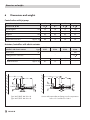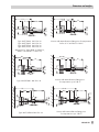
1
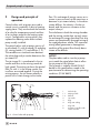
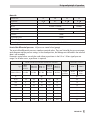
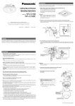
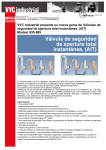
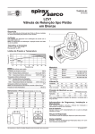
Electric Control Valves with Jet Pump
Type 3267/5857, Type 3267/5824, Type 3267/5825,
Type 3267/5757, Type 3267/5724, Type 3267/5725
Pneumatic Control Valves with Jet Pump
Type 3267/2780
Valve with Jet Pump in version with screwed ends
Fig. 1 · Type 3267/5824
Mounting and
Operating Instructions
EB 5895 EN
Edition April 2010
Definitions of the signal words used in these instructions
! DANGER!
DANGER indicates a hazardous situation
which, if not avoided, will result in death or
serious injury.
WARNING!
WARNING indicates a hazardous situation
which, if not avoided, could result in death
or serious injury.
2
EB 5895 EN
NOTICE
NOTICE indicates a property damage
message.
Note: Supplementary explanations,
information and tips
Contents
Contents
1
Important safety instructions . . . . . . . . . . . . . . . . . . . . . . 5
2
2.1
2.1.1
2.1.2
2.2
2.3
2.4
2.5
Design and principle of operation . . . . . . . . . . . . . . . . . . . 6
Versions . . . . . . . . . . . . . . . . . . . . . . . . . . . . . . . . 7
Control valve with jet pump . . . . . . . . . . . . . . . . . . . . . . . 7
Type 3267 Valve in version with screwed ends . . . . . . . . . . . . . . 7
Possible combinations: Type 3267 in version with screwed ends/actuator . 8
Technical data: Type 3267 in version with screwed ends . . . . . . . . . 8
Nameplate: Ventil Type 3267 in version with screwed ends . . . . . . . 10
Customer inquiries . . . . . . . . . . . . . . . . . . . . . . . . . . 10
3
3.1
3.2
3.3
Installation . . . . . . . . . .
Mounting position . . . . . . .
Strainer . . . . . . . . . . . .
Additional mounting instructions
.
.
.
.
.
.
.
.
.
.
.
.
.
.
.
.
.
.
.
.
.
.
.
.
.
.
.
.
.
.
.
.
.
.
.
.
11
12
12
12
4
4.1
4.2
4.3
Mounting, connection and configuration of the actuator
Mounting . . . . . . . . . . . . . . . . . . . . . . .
Connection . . . . . . . . . . . . . . . . . . . . . .
Configuration . . . . . . . . . . . . . . . . . . . . .
.
.
.
.
.
.
.
.
.
.
.
.
.
.
.
.
.
.
.
.
.
.
.
.
.
.
.
.
.
.
.
.
13
13
13
13
5
Jet pump adjustment . . . . . . . . . . . . . . . . . . . . . . . . . 14
6
Dimensions and weights . . . . . . . . . . . . . . . . . . . . . . . 16
.
.
.
.
.
.
.
.
.
.
.
.
.
.
.
.
.
.
.
.
.
.
.
.
.
.
.
.
.
.
.
.
.
.
.
.
.
.
.
.
.
.
.
.
EB 5895 EN
3
4
EB 5895 EN
Important safety instructions
1
Important safety instructions
For your own safety, follow these instructions concerning the mounting, start up and operation of the control valve:
4 The control valves with jet pump must be installed, started up and serviced by fully trained
and qualified personnel only, observing the accepted industry codes and practices.
Make sure employees or third persons are not exposed to any danger.
All safety instructions and warnings in these mounting and operating instructions,
particularly those concerning installation, start-up and maintenance, must be observed.
4 For appropriate operation, make sure that the control valve is only used in applications
where the operating pressure and temperatures do not exceed the operating values
based on the sizing data submitted in the order.
Note that the manufacturer does not assume any responsibility for damage caused by
external forces or any other external factors.
Any hazards which could be caused in the control valve by the process medium or
operating pressure are to be prevented by means of appropriate measures.
4 For installation and maintenance, make sure the relevant section of the pipeline is
depressurized and, depending on the process medium, drained as well. If necessary,
allow the control valve to cool down or warm up to reach ambient temperature prior to
starting any work on it.
4 The actuators are designed for use in low voltage installations.
For wiring and maintenance, you are required to observe the relevant safety regulations.
4 Take necessary measures to ensure that the power supply cannot be reconnected
inadvertently.
4 Take care while performing adjustment work on live parts. Never remove any covers!
To avoid damage to any equipment, the following also applies:
4 Proper shipping and appropriate storage are assumed.
Note: The control valves fulfill the requirements of the European Pressure Equipment Directive
97/23/EC. Valves with a CE marking have a declaration of conformity which includes information about the applied conformity assessment procedure.
The declaration of conformity is available on request.
EB 5895 EN
5
Design and principle of operation
2
Design and principle of
operation
Control valves with jet pumps are used in
control circuits, especially in district heating
supply plants. They assume both the function
of a valve for temperature control and that
of a circulator pump for the heating water
circuit. Configured as mixing valves, they
replace the reducing valve and circulator
pump usually installed.
The control valves with jet pumps consist of
a valve body (1) with jet nozzle (2) and plug
(3), mixing nozzle (1.1) and diffuser (1.2).
The variable cross-sectional area between
the valve plug and jet nozzle determines the
jet stream Q1.
The jet stream Q1 is accelerated in the jet
nozzle and flows to the mixing nozzle at
high speed. The exiting jet draws the partial
flow Q2 with it. In the mixing nozzle, the
two flows are mixed together. During the
mixing process, the jet stream releases a
portion of its kinetic energy to the intake
The turbulence in both the mixing chamber
and the mixing nozzle does not only cause
the exchange of energy described, but also
causes an exceptionally thorough mixing of
the supplied process media. This improved
mixing effect guarantees a homogenous
condition of the output flow directly downstream of the diffuser.
NOTICE
The plant data used to size the jet pump
must match the actual plant data to allow
the jet pump to fully function.
The jet pump is sized by SAMSON AG
based on the specifications made in the
questionnaire for determining the operating
conditions (TV-SK 8852).
p2t2
A
Q3
6
B
p3
t3
AB
Q2
flow. This exchange of energy causes an increase in pressure and, at the same time, a
decrease in jet stream velocity. In the downstream diffuser, the velocity is further reduced, and the pressure increases to the
output value p3.
Q1
8
p1t1
6 4 3
Fig. 2 · Control valve with jet pump
6
EB 5895 EN
2 1 1.1 1.2
1
1.1
1.2
2
3
4
6
8
Valve body
Mixing nozzle
Diffuser
Jet nozzle
Plug
Plug stem sealing
Plug stem
Actuator/controller with
electric actuator
Design and principle of operation
2.1 Versions
2.1.1 Control valve with jet pump
Electric control valves with jet pump
Type 3267/5857
PN 25
DN 15 to 25
Type 3267/5824
PN 25
DN 15 to 32
Type 3267/5825 1)
PN 25
DN 15 to 32
Electric control valves with jet pump/controllers with electric actuators for DHW heating
Type 3267/5757
PN 25
DN 15 to 25
Type 3267/5724
PN 25
DN 15 to 32
PN 25
DN 15 to 32
Type 3267/5725
1)
Electric control valves with jet pump/controllers with electric actuators for heating and cooling applications
Type 3267/5757-7
Type 3267/5725-7
1)
PN 25
DN 15 to 25
PN 25
DN 15 to 32
PN 25
DN 15 to 32
PN 25
DN 15 to 32
Pneumatic control valves with jet pump
Type 3267/2780-1
Type 3267/2780-2
2)
1)
With fail-safe action tested acc. to DIN EN 14597, register number available on request
2)
Pneumatic actuator suitable for integrated positioner attachment
2.1.2 Type 3267 Valve in version with screwed ends
Nominal size, KVS coefficients, body materials
DN
Characteristic 2: KVS
15
0.32 · 0.5
20
0.8 · 1.25
25
1.0 · 1.6
32
2.0 · 3.2
Travel
PN/material
6 mm
PN 25/CC491K
PN 25/CC499K
EB 5895 EN
7
Design and principle of operation
2.2 Possible combinations: Type 3267 in version with screwed
ends/actuator
Type
15
20
25
32
•
•
•
–
5824-10
•
•
•
•
5824-13
•
•
•
•
•
•
•
•
•
•
•
•
•
•
•
–
5724-10
•
•
•
•
5724-13
•
•
•
•
•
•
•
•
5857
Electric actuators
Nominal size DN
Refer to EB for details
EB 5857 EN
EB 5824 EN
5825-10
5825-13
5757
Controllers with electric
actuators for DHW heating
EB 5757 EN
EB 5724 EN
5725-10
5725-13
Controller with electric
actuator for heating/cooling
applications
Pneumatic actuators
•
•
•
•
5757-7
EB 5757-7 EN
•
•
•
–
5725-710
EB 5725-7 EN
•
•
•
•
•
•
•
•
•
•
•
•
2780-1
EB 5840 EN
2780-2
2.3 Technical data: Type 3267 in version with screwed ends
Nominal size
Thread size
Nominal pressure
Rated travel
Permissible temperatures
Seat/plug sealing
Type of characteristic
Leakage rate acc. to DIN EN 1349
1)
15
G
3
4
20
25
32
G1
G 1 14
G 13 4
PN 25
6 mm
–10 to 150 °C
1)
Metal sealing
Linear
Class III (≤ 0.01 % of KVS coefficient)
Types 3267/5857, 3267/5757, 3267/2780: Use an intermediate insulating piece for medium temperatures below
+5 °C and above +110 °C.
Types 3267/5824, 3267/5825 and Types 3267/5724, 3267/5725: Use an intermediate insulating piece for
medium temperatures below +5 °C and above +130 °C (networks with constant medium temperatures).
8
EB 5895 EN
Design and principle of operation
Materials
Nominal size
15
Thread size
G
3
4
Body
20
25
32
G1
G 1 14
G 13 4
CC491K or CC499K
Diffuser
CC491K or CC499K
Mixing nozzle
CW509L
CW602N
Adapter
–
CW617N
Jet nozzle
1.4305
Plug and plug stem
1.4305
Guide bushing
CW602N
Stem sealing
O-ring made of EPDM
Permissible differential pressures · All pressures stated in bar (gauge)
The permissible differential pressures stated are nominal values. They are limited by the pressure-temperature diagram and the pressure ratings. In the closed position, the leakage rate indicated in the technical
data is not exceeded.
Pneumatic control valves can only be used without a positioner in the 0.2 to 1.0 bar signal pressure
range. For all other cases, a positioner is required.
Electric actuators/Controllers with electric actuators
Type
Nominal thrust
5857
5757
5757-7
5824-10
5724-10
5824-13
5724-13
5825-10
5725-10
5725-710
5825-13
5725-13
0.3 kN
0.7 kN
0.7 kN
0.5 kN
0.5 kN
ΔpH
KVS
Pneumatic actuators
Signal
pressure
2780-1
2780-2
0.4 to
1 bar
0.4 to
2 bar
ΔpH
0.32
18
25
25
25
25
25
0.5
9
23
23
16
16
15
0.8
9
23
23
16
16
15
1.25
4
10.5
10.5
7
7
7
1.0
4
10.5
10.5
7
7
7
1.6
4
10.5
10.5
7
7
7
2.0
–
5.5
5.5
3.5
3.5
3.5
3.2
–
5.5
5.5
3.5
3.5
3.5
EB 5895 EN
9
Design and principle of operation
2.4 Nameplate: Ventil Type 3267 in version with screwed ends
1 Device index
2 Value as specified on order
3 Value as specified on order
4 Version
5 Year of manufacture
2.5 Customer inquiries
If you have any inquiries about the valve, please state the following details:
4 Type designation with device index
4 Version
4 Year of manufacture
4 Configuration ID (Var-ID)
10
EB 5895 EN
Installation
3
Refer to the installation schematic drawing
(Fig. 3) for the arrangement of the jet pump
with the required additional instruments.
Installation
NOTICE
The mounting position of the jet pump must
be lower than the position of the consumer
(radiator, air heater etc.). This ensures that
the circulation is intensified at small loads by
the thermal conditions. Otherwise, difficulties may arise while the plant is in operation.
If air heaters are used, we recommend
mounting the jet pumps directly to them.
NOTICE
– Thermometers and pressure gauges must
be installed in the generator and consumer flow pipe and in the return flow
pipe. A manually operated throttle valve
or balancing valve (4) is absolutely
necessary in the plant’s return flow pipe.
– When using the jet pump in ventilation
systems, it is absolutely necessary to
include a soft-start for winter conditions!
Keep the mixing line AB (Fig. 3) as short as
possible. Do not install check valves or
shut-off valves in this line.
2
Rinse the pipeline thoroughly before installation.
1
2
3
4
3
Q1p1t1
2
3
Control valve with jet pump
Pressure gauge
Thermometer
Balancing valve
A
KesselBoiler
or
oder
Fernwärmedistrict
heating
anschluss
connection
M
1
Q3p3t3
B
AB
2
3
4
Q2p2t2
Fig. 3 · Required pressure and temperature measuring instruments
EB 5895 EN
11
Installation
3.1 Mounting position
The Type 3267 Valve with Jet Pump must be
installed with the diffuser in the horizontal
position.
NOTICE
– The flow direction of ports A, B and AB
must match those specified in the plant
schematics (Fig. 3).
– When selecting the point of location,
make sure that the valve is still easily accessible after the plant construction has
been completed.
– Make sure the valve is mounted free of
stress. If necessary, support the piping
near the connections. Never attach the
supports to the jet pump or to the actuator.
3.2 Strainer
Install a strainer (e.g. SAMSON Type 2 NI)
at the valve inlet to prevent any sealing
parts, weld spatter or other foreign matter
carried along by the process medium from
impairing the proper functioning of the
valve, in particular, the tight shut-off.
NOTICE
– Install the strainer with the flow direction
as indicated by the arrow on the body.
– Install the strainer with the filter element
facing downwards.
– Make sure that enough space is left to
remove the filter.
12
EB 5895 EN
3.3 Additional mounting
instructions
We recommend to install a hand-operated
shut-off valve upstream of the strainer and
downstream of the control valve to be able
to shut down the plant for cleaning and
maintenance, and when the plant is not
used for longer periods of time.
Mounting, connecting and configuring the actuator
4
Mounting, connecting and
configuring the actuator
NOTICE
The instructions to mount the valve onto the
actuator, to perform electrical or pneumatic
connections as well as to configure the actuator are described in detail in the Mounting
and Operating Instructions (EB) of the actuator:
– Refer to EB 5857 EN for Type 5857
Electric Actuator
– Refer to EB 5824 EN for Type 5824
Electric Actuator
– Refer to EB 5824 EN for Type 5825
Electric Actuator
– Refer to EB 5757 EN for Type 5757
Controller with Electric Actuator
– Refer to EB 5724 EN for Type 5724
Controller with Electric Actuator
– Refer to EB 5724 EN for Type 5725
Controller with Electric Actuator
– Refer to EB 5757-7 EN for Type 5757-7
Controller with Electric Actuator
– Refer to EB 5725-7 EN for Type 5725-7
Controller with Electric Actuator
– Refer to EB 5840 EN for Type 2780
Pneumatic Actuator
It is essential to read the Mounting and
Operating Instructions of the corresponding actuator.
4.2 Connection
Perform the electrical or pneumatic connections of the actuator as described in the corresponding Mounting and Operating Instructions.
4.3 Configuration
The electric actuator versions with positioner
and the controllers with electric actuator can
be adapted to the control task.
Configure the actuator as described in the
corresponding Mounting and Operating Instructions.
4.1 Mounting
Mount the actuator onto the valve connection/intermediate insulating piece as described in the corresponding Mounting and
Operating Instructions.
EB 5895 EN
13
Jet pump adjustment
5
Adjustment
Jet pump adjustment
Sizing
NOTICE
To adjust the jet pump, the pressure and
temperature measuring instruments illustrated in Fig. 4 are absolutely necessary.
The plant data used to size the jet pump
must match the actual plant data to allow
the jet pump to fully function.
The jet pump is sized by SAMSON AG
based on the specifications made in the
questionnaire for determining the operating
conditions (TV-SK 8852).
The required temperature t3 in the consumer plant results from the ratio of the
flows Q1, Q2 and Q3 as well as the differential pressures ΔpH and Δph across the
plant.
If the temperature t3 in the consumer plant
(at full rated travel H100) is not achieved
with the network pressure ΔpH available, the
differential pressure Δph across the balancing valve (4) must be adjusted. To do this,
proceed as follows:
2
3
Q1p1t1
2
3
A
KesselBoiler
oderor
district
heating
Fernwärmeconnection
anschluss
M
1
Q3p3t3
B
AB
2
3
4
Q2p2t2
1
2
3
4
Control valve with jet pump
Pressure gauge
Thermometer
Balancing valve
Q1
Q2
Q3
p1
p2
p3
t1
t2
Flow rate in network flow
Flow rate in network return flow
Flow rate in output flow
Pressure in network flow
Pressure in network return flow
Pressure in output flow
Temperature in network flow
Temperature in network return
flow
Temperature in output flow
t3
Fig. 4 · Jet pump adjustment
14
EB 5895 EN
Jet pump adjustment
1. Determine the flow rate ratio m100 from
the temperatures t1, t2 and t3 (read off at
the thermometers) using the following
equation:
m100
Q
t −t
= 1= 3 2
Q3 t1 − t 2
2. Determine the pressure ratio ε 100 from the
pressures p1, p2 und p3 (read off at the
pressure gauges) using the following
equation:
ε 100 =
Δp h
Δp H
=
p3 − p 2
p1 − p 2
4. For optimal operation, the operating
point lies on the marked limit (Characteristic 2).
Shift the determined point of intersection
horizontally (same flow rate ratio m100 )
until it reaches the limit and read off the
corresponding pressure ratio ε 100 .
5. Using the value read from the diagram
for ε 100 and the known network pressure
ΔpH, the plant differential pressure Δph
can be calculated:
Δph = ΔpH · ε 100
3. Enter the flow rate ratio m100 and pressure ratio ε 100 on the operating diagram
(Fig. 5). The point of intersection
(operating point) must be within the
gray-shaded operational area. If not, the
jet pump has been incorrectly sized.
6. Adjust the balancing valve until the calculated differential pressure Δph is
achieved or until the correct temperature
ratio is achieved.
m100
1
0.9
0.8
Operational area
0.7
0.6
Characteristic 2 = Limit
0.5
0.4
0.3
0.2
0.1
0
0.1
0.2
0.3
0.4
0.5
0.6
ε100
The flow ratio m100 and the pressure ratio ε100 are based on the full rated travel H100.
Fig. 5 · Operating diagram: Type 3267 Valve with Jet Pump in version with screwed ends
EB 5895 EN
15
Dimensions and weights
6
Dimensions and weights
Control valves with jet pump
Nominal size A, B, AB
DN
Thread size A, B, AB
15
20
25
32
G 34
G1
G 1 14
G 134
Overall length L1
mm
65
70
75
100
Length L2
mm
100
140
180
230
Height H2
mm
45
45
45
95
Height H3
mm
175
175
175
230
Approx. kg
0.8
1.2
2.0
6.0
5857
5757
5824
5724
5825
5725
2780
Weight without actuator
Actuators/controllers with electric actuator
Actuators/
controllers with electric actuator
Type
2
Effective area
120
cm
–
Loading pressure connection
Weight
With handwheel
Approx. kg
–
–
1.5
2
Approx. kg
0.7
1.3
–
–
H3
H3
91
H2
91
L2
H2
114x70
114x70
Type 3267/5857: DN 15 to 25
Type 3267/5757: DN 15 to 25
L2
B L1
B L1
AB
EB 5895 EN
80
A
A
16
G 18
AB
Version with intermediate insulating piece for temperatures
below +5 °C and above +130 °C
Dimensions and weights
H3
113
H2
H3+80
113
L2
80
H2
L2
A
A
146x103*
146x103*
B L1
B L1
AB
AB
Type 3267/5824: DN 15 to 32
Type 3267/5825: DN 15 to 32
Type 3267/5724: DN 15 to 32
Type 3267/5725: DN 15 to 32
* Dimensions for Types 5824-13, 5825-13,
5724-13 and 5725-13: 146 x 136
H3
120.5
H2
Version with intermediate insulating piece for temperatures
below +5 °C and above +130 °C
H3+80
120.5
L2
H2
L2
A
A
Ø186
B L1
Ø186
B L1
AB
AB
Version with intermediate insulating piece
for temperatures up to 150 °C
Type 3267/2780-1: DN 15 to 32
H3+80
208
H3
208
80
H2
L2
B L1
AB
Type 3267/2780-2: DN 15 to 32
H2
L2
A
A
Ø186
80
Ø186
B L1
AB
Version with intermediate insulating piece
for temperatures up to 150 °C
EB 5895 EN
17
18
EB 5895 EN
EB 5895 EN
19
EB 5895 EN
2010-04
SAMSON AG · MESS- UND REGELTECHNIK
Weismüllerstraße 3 · 60314 Frankfurt am Main · Germany
Phone: +49 69 4009-0 · Fax: +49 69 4009-1507
Internet: http://www.samson.de