1
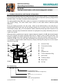
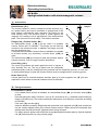
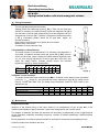
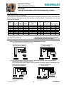
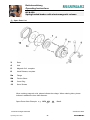
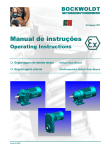
BOCKWOLDT English (GB) Operating Instructions Spring-loaded brakes with electromagnetic release Edition 04.2000 Betriebsanleitung BOCKWOLDT Operating Instructions GETRIEBEMOTORENWERK BFK458 Spring-loaded brakes with electromagnetic release 1. Product Information and Principle of Operation BFK 458 spring-applied brakes are single-disk brakes with two friction surfaces. The armature plate ( 1 ) is always one of the friction faces. Several friction-locking compression springs ( 2 ) generate the brake torque. The brake is released electromagnetically. The spring-applied brake BFK 458 is made for conversion of mechanical work and kinetic energy into thermal energy. The static brake torque allows to hold loads without rotational speed difference. During the braking procedure, the rotor ( 3 ) , which can be shifted axially on the hub ( 4 ), is pressed against the friction face via the armature plate ( 1 ), by means of the inner and outer compression springs ( 2 ). The non-asbestos friction surfaces provide high brake torques at low abrasion. The brake torque transmission between hub ( 4 ) and rotor ( 3 ) is effected by the use of a gear tooth system. When the brake is applied, the air gap sLÜ appears between magnetic coil ( 5 ) and armature plate ( 1 ). The magnetic coil ( 5 ) is energised with due DC voltage in order to release the brake. The resulting magnetic flux works against the spring force to draw the armature plate ( 1 ) to the magnetic coil ( 5 ). Thus, the rotor ( 3 ) is discharged from the spring force and can rotate freely. It is possible to obtain smaller brake torques by simply reducing the spring force via the torque adjustment ring ( 6 ). 1 s LÜ 5 13 7 11 3 2 4 6 Image 1 1 Armature Plate 2 Compression Spring 3 Rotor 4 Hub 5 Magnetic Coil 6 Torque Adjustment Ring 7 Sleeve Bolt 11 Fastening Screw 13 Brass Plate slü Air Gap 2. Product Key BFK 458 . 06 . E Construction Form Adjustable (torque reducible via adjustment) Size 06, 08, 10, 12, 14, 16, 18, 20, 25 Type Brake, Spring-Applied Brake Operating Instructions -1- BOCKWOLDT Betriebsanleitung BOCKWOLDT Operating Instructions GETRIEBEMOTORENWERK BFK458 Spring-loaded brakes with electromagnetic release 3. Accessories Hand Release ( 8 ) The manual release is used to release the brake by hand (e.g. at a power failure) and can be retrofitted. It springs back to the base positon automatically after operation. By pulling at the hand release lever, the armature plate is pulled against the magnetic coil, leading to an air gap between rotor and armature plate. The rotor can be turned easily. The brake is released. Flange ( 9a ), Friction Sheet ( 9b ) An intermediate flange ( 9a ) can be used if no suitable counter friction face is available. This flange can be fitted by screws on two reference circles. In addition, the flange can hold the dust protection ring. If a smooth and machined counter surface is available, but suitable as a friction surface (e.g. aluminium), a friction sheet ( 9b ) is used. The friction sheet ( 9b ) of rust-proof steel also protects against contact corrosion, even at longer machine downtimes. 8 Image 2 7 13 11 9b 9a 10 Cover Ring ( 10 ) h 1 max. The cover ring protects the brake against the exit or ingress of dust, humidity, dirt, etc. The ring is pulled over the completely assembled brake, with the sealing lips being inserted into the respective grooves. In case that no intermediate flange is used, the counter surface must be equipped with a receiving groove. Brass Plate ( 13 ) A brass plate can be inserted between armature plate ( 1 ) and magnetic coil ( 5 ) for fast separation, which leads to reduced incidence times of the brake. 4. Fitting Information 4.1 Installation of Brake If no suitable friction surface is available, an intermediate flange ( 9a ) or a friction sheet ( 9b ) is used. Draw hub ( 4 ) onto shaft [ fit feature k6 up to Ø 50, more than Ø 50 m6 ] aufziehen and fix axially by means of a locking ring. The torque transmission takes place via a fitting key connection according to DIN 6885. Push rotor ( 3 ) onto hub ( 4 ). Insert the fastening screws ( 11 ) through the bore holes in the magnetic coil ( 5 ) and screw them into the relevant tapped bores of the counter friction surface. Please remove the assembly clips which protect the sleeve bolts ( 7 ) against torsion during transport. For safety reasons, please now control the air gap sLÜ between armature plate ( 1 ) and magnetic coil ( 5 ) at three points, by using a feeler gauge. Operating Instructions -2- BOCKWOLDT Betriebsanleitung BOCKWOLDT Operating Instructions GETRIEBEMOTORENWERK BFK458 Spring-loaded brakes with electromagnetic release 4. Fitting Information - - The air gap sLÜ is adjusted as follows: Slightly loosen the fastening screws ( 11 ). Then use an open-end wrench for screwing the sleeve bolts ( 7 ) into the magnetic coil ( 5 ) (for reduction of the air gap) respectively out of the magnetic coil (for enlargement of the air gap). Carefully re-tighten the fastening screws ( 11 ). Afterwards please check the air gap sLÜ again, as mentioned above. Keep friction surfaces free from grease and oil residue. Make electric connection. If needed, fix dust protection ring. 4.2 Installation of Hand Release The hand release is pre-assembled. For mounting, the dimension s (see table 1) between armature plate ( 1 ) and disk ( 12 ) must be equal at both sides. Never change the hand release alignment later on, not even during adjustment of the air gap sLÜ, since this may affect the safety funtion. Instead, please secure the effected alignment position by some threadlocker. 06 08 10 Brake Size 12 14 16 18 20 25 0,2 0,2 0,2 0,3 0,3 0,3 0,4 0,4 0,5 1 1 1 1,5 1,5 1,5 2 2 2,5 Table 1 s LÜ [mm] s +0,1 [mm] Image 3 4.3 Brake Torque Alteration The brake comes with fixed nominal torque MN. A reduction of the brake torque is possible until max. . h1max (image 2): Just unscrew the torque adjustment ring ( 6 ) by using a hook wrench. Please see table 2 for the brake torque alteration values for each raster in the adjustment ring. Brake Size Brake Torque MN Reduction per raster h1max [ Nm ] [ Nm ] [ mm ] 06 4 0,2 4,7 08 8 0,35 4,7 10 16 0,8 7,6 12 32 1,3 9,6 14 60 1,7 11 16 80 1,6 10 18 150 3,6 14,9 20 260 5,6 16,4 Table 2 25 400 6,2 17,3 5. Maintenance Inspection Intervals Wearout of the friction lining on the rotor results in an enlargement of the air gap sLÜ. If the maximum admissible air gap is reached, it has to be re-adjusted to the nominal value. The degree of abrasion and thus the intervals until necessary re-adjustment of the air gap depend on the operation conditions (switching frequency, number of effected switchings, rotational speed difference). During inspection, the friction surfaces should be checked for evenness and possible grooves. Clean the brake from abrasion and dust. Operating Instructions -3- BOCKWOLDT Betriebsanleitung BOCKWOLDT Operating Instructions GETRIEBEMOTORENWERK BFK458 Spring-loaded brakes with electromagnetic release 5. Maintenance Inspection Intervals -FortsetzungThe air gap sLÜ between the armature plate and the magnetic coil must be at zero value when the brake is released. Make sure that the rotor can glide on the hub toothing. For adjustment of the air gap S LÜ please see above. Brake Size SLÜ Nominal SLÜ sLÜ max. Rotor Overlap of adjustment ring Tightening torque [ mm ] h1 max. Screws Complete lever + 0,1 mm - 0,05 mm Service brake Holding brake max. adjustment, admissible abrasion distance [ mm ] [ mm ] [ mm ] [ mm ] min. 1) max. [ mm ] [ Nm ] [ Nm ] 0,2 0,2 0,2 0,3 0,3 0,3 0,4 0,4 0,5 0,5 0,5 0,5 0,75 0,75 0,75 1,0 1,0 1,25 0,3 0,3 0,3 0,45 0,45 0,45 0,6 0,6 0,75 1,5 1,5 1,5 2,0 2,5 3,5 3,0 4,0 4,5 4,5 5,5 7,5 8,0 7,5 8,0 10,0 12,0 15,5 6,0 7,0 9,0 10,0 10,0 11,5 13,0 16,0 20,0 4,7 4,7 7,6 9,6 11,0 10,0 14,9 16,4 17,3 2,8 5,5 9,5 9,5 23 23 23 46 46 2,8 2,8 4,8 4,8 12 12 23 23 40 06 08 10 12 14 16 18 20 25 max. 1) The friction surface is made for at least 5 adjustments of the brake. Table 3 Attention, please: The brake must be in tensionless state during connection to mains supply. 6. Electric Connection 6.1 With Bridge Rectifier 6.1.1 For single-speed AC threephase motors without starting stage [Direct connection at motor terminal board] Normal brake engagement [AC single-phase switching] Fast brake engagement [DC switching] - +~ ~ brake coil brake coil - +~ ~ ~ ~ ~ ~ L1 L1 L3 L2 - connection L1 L1 L3 L2 - connection L3 L2 - connection L3 L2 - connection auxiliary contactor (e.g. at motor contactor) 6.1.2 For single-speed AC threephase motors w i t h starting stage, pole-changing motors [Additional AC voltage connection required] or for single-phase motors w i t h starting capacitor, operating capacitor and starting relay Fast brake engagement [DC switching] Normal brake engagement [AC single-phase switching] brake coil brake coil - +~ ~ L1 ~ N 230 V L1 ~ - +~ ~ N L1 110 V ~ N 230 V L1 ~ N 110 V AC single-phase connection voltage (see name plate of brake) Motor must be connected at the same time. AC single-phase connection voltage (see name plate of brake) Motor must be connected at the same time No brake release allowed at pole-changing or star-delta switching. No brake release allowed at pole-changing or star-delta switching Operating Instructions -4- auxiliary contactor (e.g. at motor contactor) BOCKWOLDT Betriebsanleitung BOCKWOLDT Operating Instructions GETRIEBEMOTORENWERK BFK458 Spring-loaded brakes with electromagnetic release 6.2 With One-Way Rectifier 6.2.1 For single-speed AC threephase motors w i t h o u t starting stage [Direct connectino at motor terminal board] Normal brake engagement [AC single-phase switching] Fast brake engagement [DC switching] - +~ ~ brake coil brake coil - +~ ~ ~ ~ ~ ~ L1 L1 L3 L2 - connection L3 L2 - connection L1 L3 L2 - connection L3 L2 - connection L1 auxiliary contactor (e.g. at motor contactor) 6.2.2 For single-speed AC threephase motors w i t h starting stage, pole-changing motors [Additional AC voltage connection required] or for single-phase motors w i t h starting capacitor, operating capacitor and starting relay Normal brake engagement [ AC single-phase switching ] Fast brake engagement [ DC switching ] brake coil brake coil - +~ ~ L1 ~ N 230 V - +~ ~ L1 L2 ~ L1 400 V ~ N 230 V L1 L2 ~ 400 V AC single-phase connection voltage (see name plate of brake) Motor must be connected at the same time. AC single-phase connection voltage (see name plate of brake) Motor must be connected at the same time. No brake release allowed at pole-changing or star-delta switching. No brake release allowed at pole-changing or star-delta switching. Operating Instructions -5- auxiliary contactor (e.g. at motor contactor) BOCKWOLDT Betriebsanleitung BOCKWOLDT Operating Instructions GETRIEBEMOTORENWERK BFK458 Spring-loaded brakes with electromagnetic release 7. Spare Parts List 3 Rotor 4 Hub 5 Magnetic Coil, complete 8 Hand Release, complete 9a Flange 9b Friction Sheet 10 Cover Ring 11 Set of Screws When ordering magnetic coils, please indicate the voltage. When ordering hubs, please indicate in addition the bore hole diameter. Spare Parts Order Example: e. g. BFK 458 Type technical changes reserved Operating Instructions 06 Pos.3 Size Version 04.2000 -6- BOCKWOLDT