1
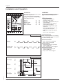
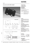
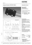
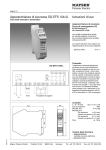
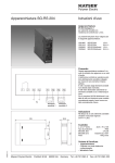
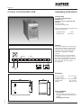
Polymer Electric Page /4 Control Unit SG-RSV 239 Operating Instructions Control Unit according to EN 50155 and EN 50121‑3‑2 classes TX, S2 in accordance with EN 50155 for sensors with 1.2 kΩ monitoring resistor These operating instructions apply to the following control units: SG-RSV 239/24 SG-RSV 239 24 V= 50-150 V= Control The Control Unit has two monitoring circuits, which operate the output relays. The electronics monitor the electrical resistance of the connected sensors which have a defined zero signal current. When the sensors are not activated (normal operating conditions), the output relays are energised. If the line is disconnected between the sensor and the control unit, the relay “fault” is de-energised. Sensor 1 Sensor 2 Enclosure W × H × D (mm) Protection class 2 plug-in connectors Cable clamps Weight 45 × 75 × 108 IP20 each 8-channel max. 2.5 mm2 approx 175 g Parts supplied 130707 v1.2 - Control Unit Enclosure with electronics module and plug connections with lift-up lock release. - Operating Instructions Mayser Polymer Electric Postfach 30 48 89020 Ulm Germany Tel. +49 731 2061-0 Fax +49 731 2061-222 Page /4 Control Unit SG-RSV 239 IMPORTANT NOTES! Please read! To ensure correct and safe operation of the unit, it must be properly transported and stored, properly installed and commissioned, and operated in accordance with its intended use. Only persons familiar with the installation, commissioning and operation, and with the corresponding qualifications to prove their skills, may work on the units. They must observe the contents of these instructions, the information given on the type plate of the unit and the relevant safety regulations for the installation and operation of electrical systems. This unit is designed in accordance with EN 50155 and EN 50121-3-2 and left the factory in a perfectly safe condition. To maintain this condition, you must observe the safety regulations marked WARNING! in these operating instructions. Failure to observe the safety regulations can lead to death, injury to personnel, or damage to the unit and other systems and equipment. Should the information given in these operating instructions be inadequate in any way, please contact your local technical centre, subsidiary or representative. When using the device outside the European Union, you must observe the relevant regulations valid for the country of use. Important notes: Technical Data - Supply voltage must be in accordance with the connecting voltage Us indicated on the type plate. - Permissible temperature range maintain sufficient distance from heat sources if installing in switch cabinet (min. 2 cm). - Fusing of the relay contacts due to risk of welding, externally with 1.0 A inert. Connecting Voltage US DC 24 V -30% to +30% DC50 to 150 V <2W SG-RSV 239/24 Voltage tolerance SG-RSV 239 Nominal frequency Frequency tolerance Power consumption Sensor Voltage max. 12 V DC Signal Voltage State max. Us (S2) (S2) Relay Data Switching current max. 1 A max. 1 A Switching voltagemax. AC 250 V max. DC 150 V Breaking capacity max. 250 W max. 30 W (AC 12) (DC 12) Switching operations mechanical > 2× 10⁷ electrical > 1× 10⁵ (250 AC V / 1 A) Operating Conditions Mayser Polymer Electric -40 °C to +70 °C (T3) max. 95% 5 g in all 3 levels Postfach 30 48 89020 Ulm Germany Tel. +49 731 2061-0 Fax +49 731 2061-222 130707 v1.2 Perm. ambient temperature range Rel. humidity Endurance limit Please note: When switching inductive loads the user must be fitted out with spark absorbers (RC-modules). Polymer Electric Page /4 Installation and Operation Installation The enclosure of the control unit can be mounted in any position: - on a 35 mm standard rail EN 50022 Wiring is connected to the cable clamps of the plug connections: Sensor 1 Sensor 2 Supply voltage Relay “fault” Relay “activated” Y1Y2 Y3Y4 A1A2 13 14 23 24 Normal operation Sensor X actuated yes no "actuated" relay de-energised no yes WARNING! Do not release terminals or connect plug connections with power on. LEDs information - LED (green) "Betrieb" (on) Operating voltage active - LED (yellow) "Betätigt Kanal X" (activated channel X) Sensor actuated, relay "Betätigt" (activated) de-energised - LED (red) "Störung Kanal X" (fault channel X) Line sensor interrupted, relay "Störung" (fault) de-energised - LED (red) "Störung allg." (general fault) Relay " fault " de-energised Commissioning After connecting up sensors, switching contacts and power, carry out a function test in the following order: Sensor not actuated - relay " activated " is energised - relay " fault " is energised Sensor actuated - LED "Betätigt Kanal X" (activated channel X) lights up - relay " activated " is de-energised Sensor disconnected - LED "Störung Kanal X" (fault channel X) lights up - relay " fault " is de-energised Fault signals power supply fault channel X internal fault yes no <10ms >500ms yes no fault state yes no autom. test fault state >10ms "fault" relay de-energised no yes 130707 v1.2 autom. test Mayser Polymer Electric Postfach 30 48 autom. test 89020 Ulm Germany Tel. +49 731 2061-0 Fax +49 731 2061-222 Page /4 Maintenance and troubleshooting Maintenance Troubleshooting and remedies 1. Unit still switched off Relay "fault" (13, 14) and Relay "activated" (23, 24) must be de-energised. Sensor not activated and Control Unit does not respond: LED "Betrieb" (on) not lit >Supply voltage off or incorrect. Check supply voltage, compare with type plate. Observe correct polarity. Fault still exists: Control Unit faulty. Replace Control Unit. The Control Unit is maintenance-free. If no shorter testing intervals are specified, check the safety system monthly in the following order: 2. Switch unit on Relay "fault" (13, 14) and relay "activated" (23, 24) must energise. 3. Activate sensor Relay "activated" (23, 24) must de-energise. Prerequisite: SG-RSV 239 connected to power supply and sensor. Sensor not activated and relay "fault" not energised: LED "Störung Kanal X" (fault channel X) lit >Sensor or supply lines faulty (connection interrupted). Check sensor with gauge: set value = 1.2 kΩ ±2%. Actual value ≠ set value: sensor or supply line faulty. Replace sensor. LED "Störung Kanal X" (fault channel X) not lit >Control Unit faulty. Connect resistor 1.2 kΩ instead of the sensor. Fault still exists: Control Unit faulty. Replace Control Unit. Sensor interrupted and relay "fault" not de-energised: >Control Unit faulty. Disconnect sensor. Relay " fault " not deenergised: Control Unit faulty. Replace Control Unit. Sensor not activated and relay "activated" not energised: LED "Betätigt Kanal X" (activated channel X) lit >Sensor or supply line faulty (short-circuit). Check sensor with gauge: set value = 1.2 kΩ ±2%. Actual value ≠ set value: sensor or supply line faulty. Replace sensor. LED "Betätigt Kanal X" (activated channel X) not lit >Control Unit is faulty Connect resistor 1.2 kΩ instead of the sensor. Fault still exists: Control Unit faulty. Replace Control Unit. Sensor actuated and relay "activated" not de-energised: LED "Betätigt Kanal X" (activated channel X) not lit >Sensor or supply line faulty (resistance change too low). Check sensor with gauge: set value " activated " < 300 Ω. Actual value > 300 Ω : sensor or supply line faulty. Replace sensor. >Control Unit faulty. Check sensor with gauge: set value " activated " < 300 Ω. Actual value < 300 Ω : Control Unit faulty. Replace Control Unit. LED "Störung allg." (general fault) lit: >Control Unit faulty. Replace Control Unit. Subject to technical modifications. Mayser Polymer Electric Postfach 30 48 89020 Ulm Germany Tel. +49 731 2061-0 Fax +49 731 2061-222 130707 v1.2 Fault can still not be detected? - Mayser Support will help: Tel. +49 731 2061-0