1
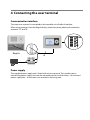
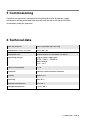
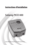
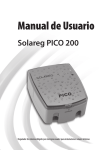
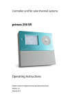
navo Room user terminal Installation and operating instructions English translation of the German original installation and operating instructions Version: 1.0 September 2014 EN Declaration of conformity Table of contents 1 Declaration of conformity ....................................................................................... 2 2 Description ............................................................................................................... 3 2.1 Overview ................................................................................................................................................. 4 3 Installing the room user terminal ............................................................................ 4 4 Connecting the user terminal .................................................................................. 5 5 Commissioning ........................................................................................................ 6 6 Technical data .......................................................................................................... 6 1 Declaration of conformity The product was manufactured and tested in accordance with CE directives and therefore bears the CE mark. 2 Description The navo room user terminal enables the user-friendly operation of all compatible Prozeda controllers from the living area. Exact mirroring of the controller user interface permits the visualisation and remote control of all controller settings, parameters and measured values. No software installation required. 2.1 Overview 1 2 ➀LCD. Mirrors the controller user interface. After 15 seconds the display changes automatically to "Room temperature display" mode. This is the standard display until a key is pressed again. ➁4 operating buttons. The same functions as with the controller. 3 Installing the room user terminal Use suitable screws and dowels for fastening the user terminal. Hang the room user terminal in the "key holes". 92 mm 4 Connecting the user terminal Communication interface The room user terminal is connected to the controller via a ProBusX interface. When using products from the Regula family, check the correct polarity of connection terminals "A" and "B". P12V B A M A Regula B 4 Power supply The supplied power supply unit is fitted with a lustre terminal. This enables you to connect the power supply unit near the controller and to install the lines – bus line and power supply line – to the room user terminal in the living area. 5 Commissioning Once the user terminal is connected to the controller and to the power supply, initialisation will be performed automatically and the room user terminal will be immediately ready for operation. 6 Technical data Housing material 100% recyclable ABS housing Dimensions L x W x D in mm 145 x 100 x 30 Protection class IP20 according to DIN 40050, EN 60529 Operating voltage Plug-in power supply unit: AC 90 ... 260 V~ / 50-60 Hz Input voltage: 12 V / 1.0 A Power consumption <1W Interfaces ProBusX communication interface Display Backlit LCD Humidity Max. 60 % Ambient temperature 0 to +40 °C Storage temperature –10 to +60 °C 1715BED001-10B-E