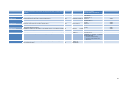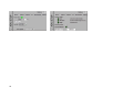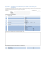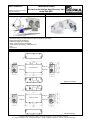
1
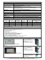
Installation and maintenance Please keep careful! maxi flat 450 - 200 Operating Instructions Heat recovery unit series Status: 08/2013 Paul Wärmerückgewinnung GmbH August-Horch-Straße 7 08141 Reinsdorf Germany Tel.: +49(0)375 - 303505 - 0 Fax: +49(0)375 - 303505 - 55 Table of contents 0 Preamble ................................................................................................................................. 3 1 Introduction ............................................................................................................................ 3 1.1 1.1.1 1.1.2 1.1.3 1.1.4 Warranty and Liability .............................................................................................................. 3 General Information ................................................................................................................. 3 Warrant Terms ......................................................................................................................... 3 Conformity ................................................................................................................................ 3 Liability ..................................................................................................................................... 3 1.2 1.2.1 Safety ....................................................................................................................................... 4 Used Symbols .......................................................................................................................... 4 2 GENERAL MAINTENANCE INSTRUCTIONS........................................................................ 4 2.1 Construction characteristics ..................................................................................................... 4 2.2 TAC technology fans ................................................................................................................ 5 2.3 About the counterflow AIR/AIR heat exchanger ...................................................................... 5 2.4 Filters ....................................................................................................................................... 5 2.5 Installation control datasheet (see appendix) .......................................................................... 5 3 INSTALLATION INSTRUCTIONS........................................................................................... 6 3.1 Installing the unit ...................................................................................................................... 6 3.2 Connecting the drain pan ......................................................................................................... 6 4 WIRING INSTRUCTIONS........................................................................................................ 7 4.1 4.1.1 4.1.2 General information ................................................................................................................. 7 Schematic of the maxi flat units ............................................................................................... 7 Schematic of the T° sensors positioning in the maxi flat unit .................................................. 7 4.2 Power supply to the fans and the control devices ................................................................... 8 5 TAC4 CONTROL SYSTEM ..................................................................................................... 9 6 MAINTENANCE .................................................................................................................... 10 6.1 Every 3 months ...................................................................................................................... 10 6.2 Every 12 months .................................................................................................................... 10 1 Appendix 1: ADVANCED SETUP TAC4 DG Appendix 2: ADVANCED SETUP on the screens of remote graphic control GRC Appendix 3: Installation control datasheet (to be filled in after starting the installation) Attachments: Technical Data maxi flat 450 Technical Data maxi flat 600 Technical Data maxi flat 1000 Technical Data maxi flat 1600 Technical Data maxi flat 2000 Check List A Maintenance Works of the User Check List B Maintenance Works of qualified Personnel Air Flow Report Commissioning and Handover Certificate CE Declaration of Conformity maxi flat 450 – maxi flat 2000 2 0 Preamble PLEASE READ THIS MANUAL CAREFULLY BEFORE INASTALLATION AND COMMISSONING! THIS MANUAL HAS BEEN MADE WITH GREATEST CARE. HOWEVER, NO RIGHTS CAN BE DERIVED THEREFROM. WE RESERVE THE RIGHT AT ANY TIME TO PARTIALLY OR ENTIRELY CHANGE THE CONTENT OF THIS MANUAL WITHOUT PRIOR NOTICE. This manual contains all the best for an assembly plant and a heat recovery unit (HRU) necessary information. The manual also serves as a handbook for installation, maintenance and customer service work. We recommend that any intervention in the appliance installation company should be consulted. Subject of this operating manual is the heat recovery unit series maxi flat in different design variants. Possible accessories are only described insofar as it is necessary for the appropriate operation. Please see the particular manuals for further information on accessories. If you have any questions that have not been answered or have not been sufficiently answered in this documentation, please contact the company Paul Wärmerückgewinnung GmbH. We will be glad to help you. 1 Introduction 1.1 1.1.1 Warranty and Liability General Information Our “general terms and conditions“ apply for the maxi flat in the currently valid version. The warranty is aligned with the warranty terms of the manufacturer. This applies to mere replacement of the material and does not include the services. They apply only in case of proof of the performed maintenance according to our regulations by a skilled installer. 1.1.2 Warrant Terms The warranty period for our MVHR devices is two years as of delivery from our factory. Warranty claims can be asserted exclusively for material and/or construction defects, which occurred during the warranty period. In the event of a warranty claim, the maxi flat may not be demounted without prior permission of the manufacturer in writing. The manufacturer grants the warranty for spare parts only when they were installed by a skilled installer. The warranty shall expire once/ when: • the warranty period has elapsed; • the device is operated without original Paul-filters; • parts are installed which were not delivered by the manufacturer; • the device is improperly used; • the defects occur due to incorrect connection, improper use or soiling of the system; • unauthorised changes or modifications on the plant are made. • The data control sheet (see Appendix) was not completed properly and in case of damage is not available. 1.1.3 Conformity CE, under formal condition that the final product integration is made in conformity with the applicable standards. 1.1.4 Liability The maxi flat device was developed and manufactured for use in so-called comfort ventilation systems. Any other use is considered as “improper use” and can result in damages to the maxi flat device or in 3 personal injuries, for which the manufacturer cannot be made liable. The manufacturer is not liable for any damage, which is due to the following causes: • Non-observance of the notes on safety, operation and maintenance, stated in this manual; • The installation was not performed according to the regulations; • Mounting of the spare parts, which were not delivered and prescribed by the manufacturer; • The defects occur due to incorrect connection, improper use or soiling of the system; • The warranty period has elapsed; • Normal wear. 1.2 Safety Please always observe the safety instructions in this operating manual. The non-observance of the safety instructions, warning notices, notes and instructions can lead to injuries or damages to the maxi flat. • Unless otherwise stated in this operating manual, only an authorised installer is entitled to install, connect, put into operation and maintain the maxi flat; • The installation of the maxi flat is to be performed according to the general local building, safety and installation instructions of the corresponding local authorities, of the water works and electric works and other official regulations and directives; • Always follow the safety instructions, warning notices, notes and instructions described in this operating manual; • Please keep this manual during the complete life time of the maxi flat in proximity to the device; • The instructions for the regular replacement of the filters or the cleaning of the supply and exhaust air valves are to be strictly followed; • The specifications stated in this document may not be changed; • Any modification of the maxi flat is prohibited; • In order to guarantee that the device will be regularly controlled, it is recommended to conclude a maintenance contract. Your supplier can give you the addresses of authorised installers in your area. 1.2.1 Used Symbols The following symbols are used in this manual: Caution, special note! Risk of: - injury of the user or the installer - damages to the device - impairment of the operation of the device if the instructions are not carried out properly 2 GENERAL MAINTENANCE INSTRUCTIONS 2.1 Construction characteristics The panels are 30mm double skin steel plates insulated. The outside panels are 0,8mm thick pre-painted (5µm primer + 20µm polyester) gray RAL 9002 color, covered with a plastic protection (to be removed after installation). The inside panel is 0,8mm galvanized steel. This combination allows the exposure of the panels to outdoors conditions, and forms a rigid structure. Thermal insulation is carried out by foam panels, self-extinguishing (M1 class), in conformity with the European environment standards, inserted between layers. The maxi flat is mono-structured. Air tightness: Internal: Class 1 as per EN 13141-7. External: Class 2 as per EN 13141-7. 4 2.2 TAC technology fans The maxi flat series is equipped with TAC technology centrifugal ventilators. The TAC4 DG control is specifically developed to take advantage of this technology. Verify that the supplied voltage corresponds to the specification of the ventilators and that the connection is made according to the supplied wiring instructions The starting up / stopping of the unit must be activated by using the softstop function on K1/K2/K3 or via the RC/GRC/MODBUS, and not by shutting off the power supply. Always check the following electrical specifications: Power supply voltage: 230VAC (210V<V<250V). Power supply frequency: 50/60 Hz. Grounding the unit is compulsory! The motor is self-protected against overloading. It is thus NOT necessary to install an electrical overload protection device. See section 3.2 for detailed wiring instructions. Insulation class Fans / unit: IP 44 RC TAC4 REC: IP 20 Nominal temperatures: -10 °C / + 55° C Conformity: CE (motors are also UL approved). Before starting the unit - If the fan wheel is rotating properly, without resistance? - Verify if the installation and the connections are made according to the applicable European standards. - Are the precautionary measures to avoid an accident taken? (Wiring, rotating parts, security measures,) Operating conditions The temperature over the fan motor cannot be lower than -10°C, or superior to 55°C. The unit is not designed to operate in an aggressive or an explosive environment. It is strongly not advised to stop and start the unit more often than every 5 minutes. 2.3 About the counterflow AIR/AIR heat exchanger Protect the heat exchanger by regularly cleaning or replacing the filters. To protect from frosting, the TAC4 DG control is as standard delivered with an inbuilt heat exchanger antifreeze system (by unbalancing the in and out airflows). There is also the KWin pre-heater option available to accomplish this if deemed necessary. The maxi flat units are specified not to exceed a frontal air speed on the heat exchanger of 2,2 m/s. 2.4 Filters Maxi flat units are delivered with G4 filters for the air ‘out’ flow and F7 filters for the air ‘in’ flow. Filters are the protectors of the heat exchanger, but also of the quality of the air you breathe. 2.5 Installation control datasheet (see appendix) When the installation is completed and running, we strongly advise that the installer fills in the installation datasheet recapitulating all the data useful for maintenance of the installation. Please keep a copy of this datasheet closely as it may come handy for many reasons: • make a clear communication in case of discussion with the manufacturer • information if you need to change parameters when necessary • this document can become an important factor in case of guarantee issues. 5 3 INSTALLATION INSTRUCTIONS 3.1 Installing the unit • Make sure the unit is installed horizontally • Leave sufficient access to the unit. Make sure it is possible to access to all the components for maintenance: fans, controls and filters. • Special care has been taken to deliver an airtight unit. Make sure the ductwork is also very airtight, especially at the connections with the unit on the supply air side. 3.2 Connecting the drain pan The maxi flat is delivered with a condensates pump (mounted and wired in our production). Connect the draining off condensates tube properly. Condensates pump Draining off condensates tube 6 4 WIRING INSTRUCTIONS 4.1 4.1.1 General information Schematic of the maxi flat units 9 2 1 9 3 9 6 5 7 4 7 8 Picture: maxi flat 450 1 2 3 4 5 6 7 8 Main switch for power supply fans and control Centralized wiring box of the CB4 TAC4 DL circuit (factory pre-wired) Supply fan (right version maxi flat 450) Exhaust fan (right version maxi flat 450) Air/Air heat exchanger + By-pass 100% Condensates tube Filters Access panel Only electrical connections made by the installer are in 1/2/3. 4.1.2 Schematic of the T° sensors positioning in the maxi flat unit To allow easier identification of the temperature sensors 3 different wire colors are used: - T1 : black wire - T2 : white wire - T3 : blue wire 7 4.2 Power supply to the fans and the control devices All the internal cables (fans, controls, sensors, …) to the main switch are factory pre-wired. All the power supply wiring that remains is the main power supply to the main switch(es). Wiring specifications: Unit type maxi flat 450 maxi flat 450+KWin maxi flat 600 maxi flat 600+KWin maxi flat 1000 maxi flat 1000+KWin maxi flat 1600 maxi flat 1600+KWin maxi flat 2000 maxi flat 2000+KWin Supply Voltage (1) Maximum amps (2) Protection type (3) Protection caliber 1 x 230 V 1 x 230 V 1 x 230 V 1 x 230 V 1 x 230 V 1 x 230 V 1 x 230 V 1 x 230 V 1 x 230 V 1 x 230 V 2 x 1,5 A 2 x 1,5 A + 3,8 A 2 x 1,5 A 2 x 1,5 A + 5 A 2 x 3,1 A 2 x 3,1 A + 7,5 A 2 x 4,6 A 2 x 4,6 A + 8,7 A 2 x 5,6 A 2 x 5,6 A + 8,7 A D – 10.000A – AC3 D – 10.000A – AC3 D – 10.000A – AC3 D – 10.000A – AC3 D – 10.000A – AC3 D – 10.000A – AC3 D – 10.000A – AC3 D – 10.000A – AC3 D – 10.000A – AC3 D – 10.000A – AC3 8A 8A 8A 16 A 8A 16 A 16 A 20 A 16 A 20 A (1) Grounding is compulsory (2) For airflow range from minimum to nominal + 20%. (3) D type “slow” reaction curves - shutoff power 10.000A - AC3. 8 5 TAC4 CONTROL SYSTEM The TAC4 control device manages the following features : - Fan airflow management (accurate knowledge of fan’s working point) Management of time slots Automatic bypass control (freecooling) Heat exchanger anti-freeze protection control The TAC4 control circuit is factory pre-wired. There are 4 ways to ‘communicate’ with the TAC4 control : • • • • RC TAC4 (LCD remote control) GRC TAC4 (graphic touchscreen display, can control up 247 units) MODBUS RTU network (usually to connect to a BMS) MODBUS TCP/IP network for a webserver type application, also allows GPRS communication The following options can be combined with TAC4 control : - RC TAC4 Option : remote control to setup, control and visualize the parameters. Please refer to TAC4 DL – RC TAC4 installation and user’s manual for detailed information - GRC TAC4 Option : graphic remote touchscreen to setup, control and visualize the parameters. Please refer to TAC4 DL – GRC TAC4 installation and user’s manual for detailed information - SAT TAC4 BA/KW Option: regulation of 2 external heat exchangers (electrical/water,hot and/or cold) please refer to SAT TAC4 BA/KW installation and user’s manual for detailed information - The SAT3 Option is a Circuit with 2 relays (2 SAT3 can be plugged) • When plugged in position OR1/OR2: status of “Fan On” warning and of “Pressure alarm” warning and/or • When plugged in position OR3/OR4 : status of water coil option circulator and of «bypass» please refer to SAT3 installation and user’s manual for detailed information - SAT TAC4 MODBUS Option : MODBUS RTU communication please refer to SAT TAC4 MODBUS installation and user’s manual for detailed information - TCP/IP TAC4 MODULE Option: MODBUS TCP/IP communication. please refer to TAC4 DL - TCP/IP installation and user’s manual for detailed information - GPRS TAC4 MODULE Option: GPRS Communication. Please refer to TAC4 DL - GPRS installation and user’s manual for detailed information . Each one of these communication configuration is fully described in a separate installation manual. 9 6 MAINTENANCE Before handling and/or opening the access panels it is compulsory to shut down the power supply using the general switch located on the front panel. Iif options KWin and\or KWout are installed, then shut down the corresponding general switches. Regular maintenance of the maxiflat unit is essential to guarantee a good operation of the device and a long life expectancy. The maintenance frequency will depend on the application and on the actual environment conditions but in a general way the following controls are advised: 6.1 1. 2. Every 3 months Check for any alarm indicated on the control device. In case of alarm refer to control manual. Check the state of filter clogging. The control device allows to set a pre-defined ‘filter clogging’ threshold (refer to installation manual). If need be replace filters. Filters that are too clogged can generate the following problems: • • • • Insufficient ventilation Excessive increase of fan rotation speed, creating excessive sound level Excessive power consumption (power consumption will increase exponentially to an increase in pressure drop, for a constant airflow) A damaged filter allows unfiltered air to enter heat exchanger (risk of clogging) and into ventilated room. List of replacement filters: Unit type maxi flat 450 Filter „extract air“ 1 x G4 (245 x 295 x 50) Filter „intake air“ 1 x G4 or 1 x F7 each (245 x 295 x 50) maxi flat 600 1 x G4 (390 x 255 x 50) 1 x G4 or 1 x F7 each (390 x 255 x 50) maxi flat 1000 1 x G4 (465 x 337 x 50) 1 x G4 or 1 x F7 each (465 x 337 x 50) maxi flat 1600 1 x G4 (965 x 337 x 50) 1 x G4 or 1 x F7 each (965 x 337 x 50) maxi flat 2000 1 x G4 (1250x337x50) 1 x G4 or 1 x F7 each (1250 x 337 x 50) 3. Inspection and cleaning of the inside of the unit: • • • 6.2 Vacuum clean any accumulation of dust in the unit. Inspect and gently vacuum clean if need be the heat exchanger. Use brush accessory to protect fins. Clean the possible condensation marks and possible accumulations in the drain pan. Every 12 months 1. Check for any alarm indicated on the control device. In case of alarm refer to installation manual. 2. Check the state of filter clogging. The control device allows to set a pre-defined ‘filter clogging’ threshold (refer to installation manual). If need be replace filters. Filters that are too clogged can generate the following problems: • Insufficient ventilation • Excessive increase of fan rotation speed, creating excessive sound level • Excessive power consumption (power consumption will increase exponentially to an increase in pressure drop, for a constant airflow) • A damaged filter allows unfiltered air to enter heat exchanger (risk of clogging) and into ventilated room. See above for list of replacement filters 3. Inspection and cleaning of the inside of the unit: • Vacuum clean any accumulation of dust in the unit. 10 • Inspect and gently vacuum clean if need be the heat exchanger. Use brush accessory to protect fins. • Clean the possible condensation marks and possible accumulations in the drain pan. • Clean drain pan • Clean the inside of the bypass. To access interior of bypass it is necessary to force-open it, proceed as follows: jump terminals IN4 and +12V on the CB4 TAC4 DG circuit board. The bypass is now open, independently of temperature conditions. • Remember to remove jump between terminals IN4 and +12V once cleaning of bypass is done. 4. Fan maintenance : Check again if power supply is shut down and fans are not running. Check cleanness of fan. Clean if necessary, be careful not to alter balancing of the fan wheel (do not remove balancing clips). Dismount fans if necessary. 5. Check airtightness of unit: Particularly check that side access panels are well closed and that airtightness seals are in a good state. Replace if necessary As of August 27th 2013 _____________________________________________________________________________________________ Although we have created our documentation carefully, we accept no liability for errors and / or lack of information that might have crept in inadvertently. 11 12 Appendix 1: TAC4 DG: ADVANCED SETUP Advanced Setup is used to enable certain specific features or to modify standard settings. The order of the table below corresponds to the sequence in the RC. If TAC4 DG + RC regulation: To start the advanced setup, press SETUP and ENTER simultaneously until ‘ADVANCED SETUP’ appears on the screen. Make selection via ↑ ↓ buttons, then press ENTER to confirm. Numbers are introduced digit by digit. If TAC4 DG + GRC regulation: Select ‘Advanced Setup’ on the GRC menu. CAUTION: some parameters considered as ‘advanced’ in the RC figure as ‘standard’ configuration of the GRC. In this case, "See setup" is mentioned in the table below, and consult MI TAC4 DG + GRC installation manual for configuration. Appendix 1 shows all the Advanced Setup screens, with a reference number. The table below refers to these numbers. If TAC4 DG + MODBUS regulation: For each feature of the advanced setup, the registry number is shown in the table. For more details see " TAC4 DG + MODBUS Installation Manual". 13 14 Function Description For all working modes (CA, LS, CPs) Password If password access is enabled, enter here the access code to enter advanced setup configuration. Modbus configuration Enter MODBUS communication configuration mode ? TAC4 DG + RC TAC4 DG + GRC TAC4 DG + MODBUS Register n° ENTRER ACCES CODE 0000 MODBUS CONFIG ? Y ADRESS : 001 BAUD RATE 9600 PARITY : N CONTROL BY RC ? Y Will be requested to access advanced setup screens / 40547 Will be displayed on upper right corner of each screen / 40543 screen 8 (Set RC Master) 40200 STOP FAN IF V<Vlow? N Vlow : 00,0 V V>Vhigh? N Vhigh : 10,0 V 0-10V on K3? N See setup screens MI TAC4 DG + GRC regulation See setup screens MI TAC4 DG + GRC regulation See setup screens MI TAC4 DG + GRC regulation See setup screens MI TAC4 DG + GRC regulation See setup screens MI TAC4 DG + GRC regulation 40501 Step Text on screen 1/2 3/4 / Modbus Configuration If yes, enter Modbus address of TAC4 unit 4.1 Modbus Configuration Select Baud rate : 1200-4800-9600-19200 Bauds 4.2 Modbus Configuration Select Parity: N (none) – E (even) – O (odd) 4.3 RC takes back control of setup (after Modbus) If LS working mode Stop fans for certain 010V signal voltage values Stop fans for certain 010V signal voltage values Stop fans for certain 010V signal voltage values Stop fans for certain 010V signal voltage values Supply and Exhaust airflows independent from one another and linked to 2 different 0-10V signals If CPs working mode Change Algorithm reaction speed If setup and control features were made via Modbus communication, possibility here to switch control to an RC. 4.4 Stop fans if actual 0-10V signal value < Vlow ? 5/6 Enter Vlow value to stop fans if actual 0-10V signal value < Vlow 6.1 Stop fans if actual 0-10V signal value > Vsup ? 7/8 Enter Vsup value to stop fans if actual 0-10V signal value > Vsup 8.1 Possibility to drive separately exhaust and supply airflows. Supply airflow rate via a 010V signal connected to K2, and exhaust airflow rate via another 0-10V signal connected to K3. The link airflow rate/signal value must be the same. 9 Configuration of the reaction speed of the CPs algorithm. 10 is Default value and is the highest reaction speed. Each -1 step corresponds to a doubling of the reaction time (10 = T, 9 = 2xT, 8 = 4xT,...). The default value is determined for most ducting application, only special applications (constant pressure in a room) require to change this parameter. Configuration of CPs mode operating logic: Negative logic: - airflow rate drops when signal on K2 > assignment value - airflow rate rises when signal on K2 < assignment value Positive Logic :: - airflow rate rises when signal on K2 > assignment value - airflow rate drops when signal on K2 < assignment value 10 SPEED CPs? 10 Screen 1 (CPs speed) 40506 11 LOGIC? NEGATIVE Screen 1 (CPs Logic) 40507 12 / 13 PRESSURE ALARM STOP FAN? N Screen 2 (Stop fans if alarm Pa ?) 40500 14 / 15 START TORQUE? 02% FANS OFF Y Screen 1 (Start torque) Screen 1 (Softstop allowed?) 40508 Change reaction logic Algorithm If CA or LS working mode Stop fans when pressure Possibility to stop the fans in case of pressure alarm (after cancelling the alarm, press alarm RESET to restart the fans.. For all working modes (CA, LS, CPs) Change Starting Torque Possibility to modify the fan’s starting torque (2% default). Disable softstop function (via control device) Disable the possibility to stop the fans using the RC (remote control) via K1/K2/K3 circuit TAC4 DG. This feature corresponds to disabling the softstop function: - If RC master: the OFF key is disabled. - If TAC4 DG master: -CA mode: if no entries connected to K1/K2/K3 then K1 airflow is activated. - LS or CPs Mode: if K1 entry not connected to +12V, then control will operate as if K1 was connected to +12V. To do this select N (O is default value) 16 / 17 / / / 40502 40503 40504 40505 40509 15 16 Boost function Configure supply/exhaust airflow rate in case of activation of Boost feature ? 18 BOOST CONFIG ? N / Boost function Enter supply airflow rate in case of activation of Boost feature ? 18.1 Enter exhaust airflow rate in case of activation of Boost feature ? 18.2 Fire Alarm Configure fire alarm operating mode ?. 19 Screen 1 (Boost : supply) Screen 1 (Boost : exhaust) / 40548 Boost function Fire Alarm 19.1 Screen 2 (IN3 contact) 40510 Fire Alarm Select how fire alarm is activated : entry IN3 is N.O or N.C (normally open or normally closed) NO : alarm is activated when in3 contact closed NC : alarm is activated when in3 contact is open Enter supply airflow rate when fire alarm is activated. SUPPLY ? xxx m³h EXHAUST ? xxx m³h FIRE AL CONFIG? N CONTACT IN3 ? N.O 19.2 Enter exhaust airflow rate when fire alarm is activated. 19.3 Bypass control Possibility to modify T° set points to control opening/closing the bypass. • Open by-pass if all following conditions are met : - Outdoor T° (S1) < indoor T° (S2). - Outdoor T° (S1) > T1. - Indoor T° (S2) > T2. 20 / 21 / 22 Screen 2 (Supply) Ecran 2 (Exhaust) Screen 3 (T1 and T2) 40511 Fire Alarm SUPPLY? 0000 m³h EXTHAUST? 0000 m³h BYPASS T VALUES : T1: 15° T2: 22° • / 40549 / 40512 40513 40514 Closing by-pass if one of the conditions is met: - Outdoor T° (S1) > T° indoor (S2). - Outdoor T° (S1) < T1 - 1°C. - Indoor T° (S2) < T2 - 2°C. 23 / 24 SET m³h IF BYPASS OPEN? N Screen 3 (set m³/h if the bypass is open ?) 40515 Bypass control Enter supply and exhaust airflow rates when by-pass is open. If you select Y, then the airflows are independent from the airflows when bypass is closed (Closed bypass airflows are function of working mode, K1,K2,K3 status or Modbus commands). Enter supply airflow rate when by-pass open. 24.1 SUPPLY 0000m³h 40516 Bypass control Enter exhaust airflow rate when by-pass open. 24.2 EXHAUST 0000m³h Antifrosting protection 25 AF? Y Antifrosting protection If KWin option not installed: Possibility to enable (Y) or not (N) the heat exchanger’s antifrost function by supply airflow rate reduction.. Possibility to modify the antifrost function parameters. Screen 3 (Supply) Screen 3 (Exhaust) Screen 6 (AF protection active ?) 25.1 CONFIG AF? N / Antifrosting protection Enter low T° value for antifrost function. 25.1.1 T° LOW AF: 0°C 40520 Antifrosting protection Enter high T° value for antifrost function. 25.1.2 T° HIGH AF: 3°C Screen 5 (T° Low AF) Screen 5 (T° High AF) Antifrosting protection Possibility to stop the fans if supply air T°< T° LOW. 25.1.3 AF STOP FAN?Y 40522 KWin If KWin pre-heat coil present (option) : Enter Setpoint T° to start ant-frosting process. If KWin or KWout option present, it is possible to modify the PID parameters. CAUTION : these modifications can be fatal and should only be carried out by qualified personnel. 26 KWin T° AF/+1,0° CONFIG PID KW ? N Screen 5 (Stop supply if T°<T° Low?) Screen 4 (Setpoint KWin) / Bypass control KWin / KWout 27 40517 40519 / 40521 40518 / 17 18 KWin KWin : possibility to modify PID parameter (PB) 27.1 KWin PID PB=005 Screen 4 (Select PID KWin) 40523 KWin KWin : possibility to modify PID parameter (Tr) 27.2 KWin : possibility to modify PID parameter (Td) 27.3 KWout KWout: possibility to modify PID parameter (PB) 27.4 KWout KWout: possibility to modify PID parameter (Tr) 27.5 KWout KWout: possibility to modify PID parameter (Td) 27.6 NV If NV option installed: Possibility to change the reaction speed configuration of the post heating algorithm (3 way valve regulation). Default value is ‘5’ for a middle speed reaction time. Each step of -1 corresponds to a doubling of the reaction time (‘5’=T, ‘4’=2xT, ‘3’=4xT, ‘2’=8xT, …). Each step of +1 corresponds to a halving of the reaction time (‘5’=T, ‘6’=T/2, ‘7’=T/4, ‘8’=T/8, …). We recommend changing this value only if you experience T° stability problems in your application. Possibility to modify the regulation parameters of the heat exchangers regulated by the SAT TAC4 BA/KW (option) Select coil type(s) regulate by the SAT TAC4 BA/KW: BA+, BA-, BA+/-, BA+/BA-, KW or BA-/KW If BA+ option installed and regulated by SAT TAC4 BA/KW : Possibility to change the reaction speed configuration of the post heating algorithm (3 way valve regulation). Default value is ‘5’ for a middle speed reaction time. Each step of -1 corresponds to a doubling of the reaction time (‘5’=T, ‘4’=2xT, ‘3’=4xT, ‘2’=8xT, …). Each step of +1 corresponds to a halving of the reaction time (‘5’=T, ‘6’=T/2, ‘7’=T/4, ‘8’=T/8, …). We recommend changing this value only if you experience T° stability problems in your application. If BA- option installed and regulated by SAT TAC4 BA/KW : Possibility to change the reaction speed configuration of the post heating algorithm (3 way valve regulation). Default value is ‘5’ for a middle speed reaction time. Each step of -1 corresponds to a doubling of the reaction time (‘5’=T, ‘4’=2xT, ‘3’=4xT, ‘2’=8xT, …). Each step of +1 corresponds to a halving of the reaction time (‘5’=T, ‘6’=T/2, ‘7’=T/4, ‘8’=T/8, …). We recommend changing this value only if you experience T° stability problems in your application. Choice of information delivered by 0-10V OUT1 output connection : airflow or pressure on one fan (default value is airflow on fan F1). Choice of information delivered by 0-10V OUT2 output connection : airflow or pressure on one fan (default value is pressure on fan F1). Enable post-ventilation feature (allow fans to run during a certain amount of time after softstop is activated). Caution : if Preheat KWin and/or Post-heat KWout, and/or SAT BA/KW is installed, the post-ventilation feature is automatically enabled. It is then impossible to set it to ‘NO’. Enter post-ventilation time (in seconds) Caution: if pre or post electrical heating (KWin / KWout / KWext), time must be of at least 90 seconds. 28 Screen 4 (Select PID KWin) Screen 4 (Select PID KWin) Screen 7 (Select PID KWout) Screen 7 (Select PID KWout) Screen 7 (Select PID KWout) Screen 6 (NV speed) 40524 KWin KWin PID Ti=030 KWin PID Td=011 KWoutPID PB=005 KWoutPID Ti=030 KWoutPID Td=011 NV/BA SPEED 05 SAT BA ? NO TYPE BA ? KW/BANV/BA SPEED 05 / Screen 6 or 7 (Sat BA?) Screen 6 (BA+ speed) 40550 29.1.2 BASPEED 05 Screen 6 (BA- speed) 40551 30 Screen 1 (OUT1 (0-10V)) Screen 1 (OUT2 (0-10V)) Screen 6 (Post-vent. ?) 40530 32 Out 1 Pa F1 Out 2 Pa F1 POST VENT? N 32.1 TIME PV 0090 sec Screen 6 (Delay) 40533 SAT BA SAT BA SAT BA SAT BA 0-10V output signal 0-10V output signal Post ventilation Post ventilation 29 29.1 29.1.1 31 40525 40527 40528 40529 40526 / 40526 40531 40532 19 20 Operating time Possibility to enable a fan operating time counter feature. The purpose is to report an maintenance alarm and/or to stop the fans after a certain time of operation. 33 FAN RUN TIME? N Enabled if one of the operating time features is enabled. (see hereunder / cfr screen 2) 40534 Operating time Reset operating time counter to 0 33.1 TIME RESET ? N 40252 Operating time Enable display of operating time 33.2 DISPLAY TIME? N Operating time Enable maintenance alarm after a certain operating time ? 33.3 SERVICE ALARM? N Operating time Enter operating time limit (in hours) to generate a maintenance alarm. 33.3.1 TIME ? 000000 h Operating time Enable ‘fan stop’ alarm after a certain operating time ? 33.4 STOP FAN? N Operating time 33.4.1 TIME ? 000000 h 34 Access Code Enter operating time limit (in hours) to generate a ‘fan stop’ alarm. The fans will be stopped after this limit is passed. Possibility to display only the alarms on the graphic screen. If no alarm is activated then "Vent OK" is displayed. Possibility to activate an access code to allow access to setup and advanced setup. Enter access code to setup and advanced setup (4 decimals). 35.1 Screen 8 (Access code ?) Screen 8 Possibility to configure 3 different access code levels : - Access to control level only - Access to control and setup only - Full access 40546 Access Code DISPLAY ONLY? N ACCESS CODE? N CODE 0000 Screen 2 (time reset ?) Screen 2 (Display time ?) Screen 2 (Service alarm ?) Screen 2 (xxxxh) Screen 2 (stop fan ?) Screen 2 (xxxxh) / Full Reset Possibility to operate a general factory reset. All factory settings are then regenerated. 36 End of advanced setup 37 Operating time 35 FACTORY RESET? N END SETUP ALARM 40535 40536 40537 40538 40539 40540 40541 40542 40547 40251 21 22 Appendix 2: Advanced Setup screens on the GRC Screen 1 Screen 2 Screen 3 Screen 4 Screen 5 Screen 6 Screen 7 Screen 8 23 24 Appendix 3: Installation control datasheet (to be filled in after starting the installation) To facilitate future interventions in the scheme, please enter all made specific settings. Please have this document before contacting us. Without this document can help may not be possible. Installed by: installation date: ___/___/___ Name: ____________________________________________ Company: ____________________________________________ Address: ____________________________________________ Telephone:___________________________________________ CONFIGURATION PARAMETERS: 1 maxi flat model 2 Working mode 3 if CA mode: 4 if LS mode: 5 if CPs mode: 6 7 % EXT/PUL Pressure alarm (modes CA / LS only ) CA LS CPs others m³h K1 = m³h K2 = m³h K3 = Vmin = Vmax = m³h≡Vmin = m³h≡Vmax = % on K3 = Asignment Pa= V (oder Pa) % on K3 = % Activated ? ja / nein If yes: Automatic / manual setup Initialisation: Supply air : m³h Pa Exhaust air : m³h Pa Indicate here all changes made in the advanced setup, if any: VALUES READ OFF DISPLAY WHEN MAXI flat in OPERATION: 1 Supply airflow 2 Supply pressure 3 Exhaust airflow 4 Exhaust pressure m³/h Pa m³/h Pa Date: 26/08/2013 Technical Data Mechanical Ventilation Heat Recovery Unit Subject to change in the interest of technical progress. maxi flat 450 Unit design of the product line (fig. maxi flat 450): 1 2 3 4 5 6 7 8 Product photo: Main switch for power supply fans and control Centralized wiring box of the CB4 TAC4 DG circuit (factory pre-wired) Supply fan (right device design) Exhaust fan (right device design) Air/air – heat exchanger and bypass Cable gland for performing condensate hose Filter Access door Unit dimensions: Exhaust air Supply air View from below Intake air Extract air Right device design Supply air Exhaust air View from below Intake air Extract air Left device design © Paul Wärmerückgewinnung GmbH • August-Horch-Straße 7 • 08141 Reinsdorf • Germany Tel: +49(0)375-303505-0 • Fax: +49(0)375-303505-55 • E-Mail: [email protected] • Internet: www.paul-lueftung.de Technical Spezification: Air flow: Demension (LxWxH): Weight: Duct connection: Electrical connection: Power input: IP Code (acc. to DIN 40050): Operating range: Heat exchanger: Fans: Filter: Housing: Condensate drain: Summer operation: 50 – 450 m³/h (1100 x 665 x 360) mm 111 kg (Base unit without any additional components) DN 200 Fans and control devices: 1 x 230 V, 50/60 Hz; on main switch (pre-wired with centralized wiring box) Electric pre-heating, optionally: 1 x 230 V, 50/60 Hz; separate main switch (pre-wired with main switch) 700 W (Base unit without any additional components) IP 44 (Fany) IP 20 (RC TAC4 REC) -20°C (lower value if option KWin) to +50°C Aluminum cross counterflow heat exchanger, sea water resistand EC direct current radial fans Filter G4 (Intake air and extract air), optional F7 (Intake air) Compact housing made of an anodised aluminium structure and acoustically and thermally insulated panels in painted steel on the outside (RAL9002) and galvanised steel inside. Stainless steel drip pan, condensate pump and condensate hose ∅ 6 mm (1/4”) ID motorized summer bypass, temperature-controlled, heat exchanger is 100% shut off Operating Data: 1) 2) air flow Heat exchanger 1) efficiency m³/h 100 200 300 450 % 95,6 93,4 92,1 90,7 Supply air 1) temperature (after exchanger) °C 20,6 19,9 19,5 19,0 SFP Power 2) absorbed Sound pessure level2) (open field in 3 m distance) W/m³/h 0,08 0,21 0,38 0,73 W 8 42 114 330 dB(A) 11,7 22,6 29,5 36,4 Values for supply and extract air volume flow at tAu = -10 °C, ϕAu = 90 % r.F. and tAb = 22 °C, ϕAb = 50 % r.F. at external pressure of 100 Pa TAC4 control system: • • • • • • • • • • • • Fan airflow management (accurate knowledge of fan’s working point) Management of time slots depending from the control units Signaling/information for all alarms Fire alarm management Boost function Automatic bypass control (freecooling) Automatic opening and closing motrised dampers (option) Automatic anti-freeze protection of the counterflow Regulation of external post-heating/cold coil (option) Display of all the operating parameters Control and display systems via WEB pages (TCP/IP or GPRS modules) Networking units via MODBUS, KNX, or BAcnet communication Control options / communications: RC TAC4, Remote Control with LCD TCP/IP TAC4 MODULE This is a communication module in TCP/IP with built-in web server This module can be combined with an RC but not with a GRC Size: 122 x 66 mm Cable to the control unit: IYSTY 2x2x0,6; max. 1000 m; by costumer GRCTAC4, Grafic Remote Control with touch display - can control up to 247 units Size: 152 x 87 mm Cable to the control unit: IYSTY 2x2x0,6 with RS-232-connector; 3 m GPRS TAC4 MODULE This is a communication module in GPRS with built-in web server This module can be combined with an RC but not with a GRC SAT TAC4 MODBUS MODULE MODBUS RTU communication circuit to be plugged in the TAC4 regulation circuit. © Paul Wärmerückgewinnung GmbH • August-Horch-Straße 7 • 08141 Reinsdorf • Germany Tel: +49(0)375-303505-0 • Fax: +49(0)375-303505-55 • E-Mail: [email protected] • Internet: www.paul-lueftung.de Date: 26/08/2013 Technical Data Mechanical Ventilation Heat Recovery Unit Subject to change in the interest of technical progress. maxi flat 600 Unit design of the product line (fig. maxi flat 450): 1 2 3 4 5 6 7 8 Product photo: Main switch for power supply fans and control Centralized wiring box of the CB4 TAC4 DG circuit (factory pre-wired) Supply fan (right device design at maxi flat 450) Exhaust fan (right device design at maxi flat 450) Air/air – heat exchanger and bypass Cable gland for performing condensate hose Filter Access door for each filter Unit dimensions: Supply air Exhaust air View from below Extract air Intake air Right device design Supply air Exhaust air View from below Extract air Intake air Left device design © Paul Wärmerückgewinnung GmbH • August-Horch-Straße 7 • 08141 Reinsdorf • Germany Tel: +49(0)375-303505-0 • Fax: +49(0)375-303505-55 • E-Mail: [email protected] • Internet: www.paul-lueftung.de Technical Spezification: Air flow: Demension (LxWxH): Weight: Duct connection: Electrical connection: Power input: IP Code (acc. to DIN 40050): Operating range: Heat exchanger: Fans: Filter: Housing: Condensate drain: Summer operation: 50 – 600 m³/h (1490 x 955 x 320) mm 138 kg (Base unit without any additional components) DN 250 Fans and control devices: 1 x 230 V, 50/60 Hz; on main switch (pre-wired with centralized wiring box) Electric pre-heating, optionally: 1 x 230 V, 50/60 Hz; separate main switch (pre-wired with main switch) 700 W (Base unit without any additional components) IP 44 (Fany) IP 20 (RC TAC4 REC) -20°C (lower value if option KWin) to +50°C Aluminum cross counterflow heat exchanger, sea water resistand EC direct current radial fans Filter G4 (Intake air and extract air), optional F7 (Intake air) Compact housing made of an anodised aluminium structure and acoustically and thermally insulated panels in painted steel on the outside (RAL9002) and galvanised steel inside. Stainless steel drip pan, condensate pump and condensate hose ∅ 6 mm (1/4”) ID motorized summer bypass, temperature-controlled, heat exchanger is 100% shut off Operating Data: 1) 2) air flow Heat exchanger 1) efficiency m³/h 150 300 450 600 % 95,3 93,1 91,8 90,8 Supply air 1) temperature (after exchanger) °C 20,5 19,8 19,4 19,1 SFP Power 2) absorbed Sound pessure level2) (open field in 3 m distance) W/m³/h 0,08 0,20 0,34 0,52 W 12 60 153 310 dB(A) 13,8 25,3 32,2 37,2 Values for supply and extract air volume flow at tAu = -10 °C, ϕAu = 90 % r.F. and tAb = 22 °C, ϕAb = 50 % r.F. at external pressure of 100 Pa TAC4 control system: • • • • • • • • • • • Fan airflow management (accurate knowledge of fan’s working point) Management of time slots depending from the control units Signaling/information for all alarms Fire alarm management Boost function Automatic bypass control (freecooling) Automatic opening and closing motrised dampers (option) Automatic anti-freeze protection of the counterflow Regulation of external post-heating/cold coil (option) Display of all the operating parameters Control and display systems via WEB pages (TCP/IP or GPRS modules) Networking units via MODBUS, KNX, or BAcnet communication Control options / communications: RC TAC4, Remote Control with LCD TCP/IP TAC4 MODULE This is a communication module in TCP/IP with built-in web server This module can be combined with an RC but not with a GRC Size: 122 x 66 mm Cable to the control unit: IYSTY 2x2x0,6; max. 1000 m; by costumer GRCTAC4, Grafic Remote Control with touch display - can control up to 247 units Size: 152 x 87 mm Cable to the control unit: IYSTY 2x2x0,6 with RS-232-connector; 3 m GPRS TAC4 MODULE This is a communication module in GPRS with built-in web server This module can be combined with an RC but not with a GRC SAT TAC4 MODBUS MODULE MODBUS RTU communication circuit to be plugged in the TAC4 regulation circuit. © Paul Wärmerückgewinnung GmbH • August-Horch-Straße 7 • 08141 Reinsdorf • Germany Tel: +49(0)375-303505-0 • Fax: +49(0)375-303505-55 • E-Mail: [email protected] • Internet: www.paul-lueftung.de Date: 26/08/2013 Technical Data Mechanical Ventilation Heat Recovery Unit Subject to change in the interest of technical progress. maxi flat 1000 Unit design of the product line (fig. maxi flat 450): 1 2 3 4 5 6 7 8 Product photo: Main switch for power supply fans and control Centralized wiring box of the CB4 TAC4 DG circuit (factory pre-wired) Supply fan (right device design at maxi flat 450) Exhaust fan (right device design at maxi flat 450) Air/air – heat exchanger and bypass Cable gland for performing condensate hose Filter Access door for each filter Unit dimensions: Supply air Exhaust air View from below Extract air Intake air Right device design Supply air View from below Extract air Exhaust air Intake air Left device design © Paul Wärmerückgewinnung GmbH • August-Horch-Straße 7 • 08141 Reinsdorf • Germany Tel: +49(0)375-303505-0 • Fax: +49(0)375-303505-55 • E-Mail: [email protected] • Internet: www.paul-lueftung.de Technical Spezification: Air flow: Demension (LxWxH): Weight: Duct connection: Electrical connection: Power input: IP Code (acc. to DIN 40050): Operating range: Heat exchanger: Fans: Filter: Housing: Condensate drain: Summer operation: 100 –1000 m³/h (1550 x 1105 x 400) mm 172 kg (Base unit without any additional components) DN 250 Fans and control devices: 1 x 230 V, 50/60 Hz; on main switch (pre-wired with centralized wiring box) Electric pre-heating, optionally: 1 x 230 V, 50/60 Hz; separate main switch (pre-wired with main switch) 1500 W (Base unit without any additional components) IP 44 (Fany) IP 20 (RC TAC4 REC) -20°C (lower value if option KWin) to +50°C Aluminum cross counterflow heat exchanger, sea water resistand EC direct current radial fans Filter G4 (Intake air and extract air), optional F7 (Intake air) Compact housing made of an anodised aluminium structure and acoustically and thermally insulated panels in painted steel on the outside (RAL9002) and galvanised steel inside. Stainless steel drip pan, condensate pump and condensate hose ∅ 6 mm (1/4”) ID motorized summer bypass, temperature-controlled, heat exchanger is 100% shut off Operating Data: 1) 2) air flow Heat exchanger 1) efficiency m³/h 250 500 750 1000 % 95,5 93,4 92,1 91,1 Supply air 1) temperature (after exchanger) °C 20,6 19,9 19,5 19,2 SFP Power 2) absorbed Sound pessure level2) (open field in 3 m distance) W/m³/h 0,08 0,20 0,36 0,56 W 21 100 273 559 dB(A) 16,8 27,8 34,7 39,6 Values for supply and extract air volume flow at tAu = -10 °C, ϕAu = 90 % r.F. and tAb = 22 °C, ϕAb = 50 % r.F. at external pressure of 100 Pa TAC4 control system: • • • • • • • • • • • Fan airflow management (accurate knowledge of fan’s working point) Management of time slots depending from the control units Signaling/information for all alarms Fire alarm management Boost function Automatic bypass control (freecooling) Automatic opening and closing motrised dampers (option) Automatic anti-freeze protection of the counterflow Regulation of external post-heating/cold coil (option) Display of all the operating parameters Control and display systems via WEB pages (TCP/IP or GPRS modules) Networking units via MODBUS, KNX, or BAcnet communication Control options / communications: RC TAC4, Remote Control with LCD TCP/IP TAC4 MODULE This is a communication module in TCP/IP with built-in web server This module can be combined with an RC but not with a GRC Size: 122 x 66 mm Cable to the control unit: IYSTY 2x2x0,6; max. 1000 m; by costumer GRCTAC4, Grafic Remote Control with touch display - can control up to 247 units Size: 152 x 87 mm Cable to the control unit: IYSTY 2x2x0,6 with RS-232-connector; 3 m GPRS TAC4 MODULE This is a communication module in GPRS with built-in web server This module can be combined with an RC but not with a GRC SAT TAC4 MODBUS MODULE MODBUS RTU communication circuit to be plugged in the TAC4 regulation circuit. © Paul Wärmerückgewinnung GmbH • August-Horch-Straße 7 • 08141 Reinsdorf • Germany Tel: +49(0)375-303505-0 • Fax: +49(0)375-303505-55 • E-Mail: [email protected] • Internet: www.paul-lueftung.de Date: 26/08/2013 Technical Data Mechanical Ventilation Heat Recovery Unit Subject to change in the interest of technical progress. maxi flat 1600 Unit design of the product line (fig. maxi flat 450): 1 2 3 4 5 6 7 8 Product photo: Main switch for power supply fans and control Centralized wiring box of the CB4 TAC4 DG circuit (factory pre-wired) Supply fan (right device design at maxi flat 450) Exhaust fan (right device design at maxi flat 450) Air/air – heat exchanger and bypass Cable gland for performing condensate hose Filter Access door for each filter Unit dimensions: Supply air Exhaust air View from below Extract air Intake air Right device design Supply air Exhaust air Extract air View from below Intake air Left device design © Paul Wärmerückgewinnung GmbH • August-Horch-Straße 7 • 08141 Reinsdorf • Germany Tel: +49(0)375-303505-0 • Fax: +49(0)375-303505-55 • E-Mail: [email protected] • Internet: www.paul-lueftung.de Technical Spezification: Air flow: Demension (LxWxH): Weight: Duct connection: Electrical connection: Power input: IP Code (acc. to DIN 40050): Operating range: Heat exchanger: Fans: Filter: Housing: Condensate drain: Summer operation: 100 –1600 m³/h (1550 x 1745 x 400) mm 247 kg (Base unit without any additional components) DN 315 Supply air and exhaust air, Rectangle duct (934 x 280) mm Intake air and extract air Fans and control devices: 1 x 230 V, 50/60 Hz; on main switch (pre-wired with centralized wiring box) Electric pre-heating, optionally: 3 x 400 V +N, 50/60 Hz;; separate main switch (pre-wired with main switch) 2200 W (Base unit without any additional components) IP 44 (Fany) IP 20 (RC TAC4 REC) -20°C (lower value if option KWin) to +50°C Aluminum cross counterflow heat exchanger, sea water resistand EC direct current radial fans Filter G4 (Intake air and extract air), optional F7 (Intake air) Compact housing made of an anodised aluminium structure and acoustically and thermally insulated panels in painted steel on the outside (RAL9002) and galvanised steel inside. Stainless steel drip pan, condensate pump and condensate hose ∅ 6 mm (1/4”) ID motorized summer bypass, temperature-controlled, heat exchanger is 100% shut off Operating Data: 1) 2) air flow Heat exchanger 1) efficiency m³/h 400 800 1200 1600 % 95,5 93,4 92,1 91,1 Supply air 1) temperature (after exchanger) °C 20,6 19,9 19,5 19,2 SFP Power 2) absorbed Sound pessure level2) (open field in 3 m distance) W/m³/h 0,07 0,19 0,37 0,59 W 27 151 442 559 dB(A) 18,1 31,2 40,6 47,3 Values for supply and extract air volume flow at tAu = -10 °C, ϕAu = 90 % r.F. and tAb = 22 °C, ϕAb = 50 % r.F. at external pressure of 100 Pa TAC4 control system: • • • • • • • • • • • • Fan airflow management (accurate knowledge of fan’s working point) Management of time slots depending from the control units Signaling/information for all alarms Fire alarm management Boost function Automatic bypass control (freecooling) Automatic opening and closing motrised dampers (option) Automatic anti-freeze protection of the counterflow Regulation of external post-heating/cold coil (option) Display of all the operating parameters Control and display systems via WEB pages (TCP/IP or GPRS modules) Networking units via MODBUS, KNX, or BAcnet communication Control options / communications: RC TAC4, Remote Control with LCD TCP/IP TAC4 MODULE This is a communication module in TCP/IP with built-in web server This module can be combined with an RC but not with a GRC Size: 122 x 66 mm Cable to the control unit: IYSTY 2x2x0,6; max. 1000 m; by costumer GRCTAC4, Grafic Remote Control with touch display - can control up to 247 units Size: 152 x 87 mm Cable to the control unit: IYSTY 2x2x0,6 with RS-232-connector; 3 m GPRS TAC4 MODULE This is a communication module in GPRS with built-in web server This module can be combined with an RC but not with a GRC SAT TAC4 MODBUS MODULE MODBUS RTU communication circuit to be plugged in the TAC4 regulation circuit. © Paul Wärmerückgewinnung GmbH • August-Horch-Straße 7 • 08141 Reinsdorf • Germany Tel: +49(0)375-303505-0 • Fax: +49(0)375-303505-55 • E-Mail: [email protected] • Internet: www.paul-lueftung.de Date: 26/08/2013 Technical Data Mechanical Ventilation Heat Recovery Unit Subject to change in the interest of technical progress. maxi flat 2000 Unit design of the product line (fig. maxi flat 450): 1 2 3 4 5 6 7 8 Product photo: Main switch for power supply fans and control Centralized wiring box of the CB4 TAC4 DG circuit (factory pre-wired) Supply fan (right device design at maxi flat 450) Exhaust fan (right device design at maxi flat 450) Air/air – heat exchanger and bypass Cable gland for performing condensate hose Filter Access door for each filter Unit dimensions: Supply air Exhaust air Extract air View from below Intake air Right device design Supply air Exhaust air Extract air View from below Intake air Left device design © Paul Wärmerückgewinnung GmbH • August-Horch-Straße 7 • 08141 Reinsdorf • Germany Tel: +49(0)375-303505-0 • Fax: +49(0)375-303505-55 • E-Mail: [email protected] • Internet: www.paul-lueftung.de Technical Spezification: Air flow: Demension (LxWxH): Weight: Duct connection: Electrical connection: Power input: IP Code (acc. to DIN 40050): Operating range: Heat exchanger: Fans: Filter: Housing: Condensate drain: Summer operation: 100 –2000 m³/h (1700 x 2045 x 400) mm 302 kg (Base unit without any additional components) DN 315 Supply air and exhaust air, Rectangle duct (1219 x 280) mm Intake air and extract air Fans and control devices: 1 x 230 V, 50/60 Hz; on main switch (pre-wired with centralized wiring box) Electric pre-heating, optionally: 3 x 400 V +N, 50/60 Hz;; separate main switch (pre-wired with main switch) 2200 W (Base unit without any additional components) IP 44 (Fany) IP 20 (RC TAC4 REC) -20°C (lower value if option KWin) to +50°C Aluminum cross counterflow heat exchanger, sea water resistand EC direct current radial fans Filter G4 (Intake air and extract air), optional F7 (Intake air) Compact housing made of an anodised aluminium structure and acoustically and thermally insulated panels in painted steel on the outside (RAL9002) and galvanised steel inside. Stainless steel drip pan, condensate pump and condensate hose ∅ 6 mm (1/4”) ID motorized summer bypass, temperature-controlled, heat exchanger is 100% shut off Operating Data: 1) 2) air flow Heat exchanger 1) efficiency m³/h 500 1000 1500 2000 % 95,5 93,4 92,1 91,1 Supply air 1) temperature (after exchanger) °C 20,6 19,9 19,5 19,2 SFP Power 2) absorbed Sound pessure level2) (open field in 3 m distance) W/m³/h 0,08 0,21 0,40 0,65 W 40 213 606 1293 dB(A) 19,8 30,9 38,5 44,6 Values for supply and extract air volume flow at tAu = -10 °C, ϕAu = 90 % r.F. and tAb = 22 °C, ϕAb = 50 % r.F. at external pressure of 100 Pa TAC4 control system: • • • • • • • • • • • Fan airflow management (accurate knowledge of fan’s working point) Management of time slots depending from the control units Signaling/information for all alarms Fire alarm management Boost function Automatic bypass control (freecooling) Automatic opening and closing motrised dampers (option) Automatic anti-freeze protection of the counterflow Regulation of external post-heating/cold coil (option) Display of all the operating parameters Control and display systems via WEB pages (TCP/IP or GPRS modules) Networking units via MODBUS, KNX, or BAcnet communication Control options / communications: RC TAC4, Remote Control with LCD TCP/IP TAC4 MODULE This is a communication module in TCP/IP with built-in web server This module can be combined with an RC but not with a GRC Size: 122 x 66 mm Cable to the control unit: IYSTY 2x2x0,6; max. 1000 m; by costumer GRCTAC4, Grafic Remote Control with touch display - can control up to 247 units Size: 152 x 87 mm Cable to the control unit: IYSTY 2x2x0,6 with RS-232-connector; 3 m GPRS TAC4 MODULE This is a communication module in GPRS with built-in web server This module can be combined with an RC but not with a GRC SAT TAC4 MODBUS MODULE MODBUS RTU communication circuit to be plugged in the TAC4 regulation circuit. © Paul Wärmerückgewinnung GmbH • August-Horch-Straße 7 • 08141 Reinsdorf • Germany Tel: +49(0)375-303505-0 • Fax: +49(0)375-303505-55 • E-Mail: [email protected] • Internet: www.paul-lueftung.de Date: 11/07/13 Checklist A Maintenance by customer Subject to change in the interest of technical progress. Maintenance Work Enter date in the quarter 1. Change both filters in the MVHR unit (change every 90 days) Quarter Year I II III IV 201... 201... 201... 201... 201... 201... 201... 202... 202... 202... 2. Clean extract air prefilter / filter in extract air valves (change approx. every 2 months) Quarter Year I II III IV 201... 201... 201... 201... 201... 201... 201... 202... 202... 202... 3. Change other filters in the system (outdoor air intake - also at ground heat exchanger) – all 6-12 months) Quarter Year I II III IV 201... 201... 201... 201... 201... 201... 201... 202... 202... 202... © Paul Wärmerückgewinnung GmbH • August-Horch-Straße 7 • 08141 Reinsdorf • Germany Tel: +49(0)375-303505-0 • Fax: +49(0)375-303505-55 • E-Mail: [email protected] • Internet: www.paul-lueftung.de Date: 11/07/13 Subject to change in the interest of technical progress. Checklist B Maintenance by skilled personnel Maintenance Enter result − − Inspection of MVHR unit based on DIN 1946-6 Informal report for comments on MVHR unit's condition − Use additional sheet of paper for adding reports of subsequent years No. Components Action / Interval (yearly) Result Components cleaned? - fans - Heat exchanger yes / no - air-contacting surfaces of the device - preheater - condensate pan, siphon, 1 Fan / MVHR unit Frost protection device functional? yes / no Structure-borne-noise transmission, fixings yes / no are avoided? Preheater / vaporizer / heat exchanger are yes / no not contaminated? Status indicators are working? yes / no Working? yes / no Condensate 2 drain and siphon Condensate disposal OK? yes / no Cable connections and clamp fixing seyes / no Electronic concure? 3 trols Control units working? yes / no Cleaning done (if required)? Test OK? yes / no Heat insulation and vapor barrier diffusionAir ducts / heat yes / no 4 close OK? insulation Flexible connections between MVHR and air yes / no ducts OK? Changeover working? yes / no Outdoor air intake free? yes / no Ground to air 5 heat exchanger Condition of prefilter OK? yes / no (if available) Condensate drain OK? yes / no Cleaning of the GHE (rinsing) yes / no Fan / MVHR unit and fireplace Safety device with firing installation 6 yes / no operating mode working? (if available) Fan / MVHR unit 7 / other filters, Filters of correct filter class installed? yes / no filter condition Fit and lock OK? yes / no Extract air / sup8 Filter condition OK? yes / no ply air outlet Air flow according air flow report OK? yes / no Free cross-section? yes / no Overflow air 9 No structure-borne / airborne noise transducts yes / no mission? 201... 201... 201... 201... © Paul Wärmerückgewinnung GmbH • August-Horch-Straße 7 • 08141 Reinsdorf • Germany Tel: +49(0)375-303505-0 • Fax: +49(0)375-303505-55 • E-Mail: [email protected] • Internet: www.paul-lueftung.de 201... Date: 23/08/2012 Subject to change in the interest of technical progress. Air Flow Report Operating condition, functional check1), instruction Customer data Surname: First name: Tel: Street: ZIP: Town: Serial-No.: Built: Construction project: MVHR-type: Measured data Measuring equipment used: Fault descriptions during measurement: Indoor temperature2) Outdoor temperature2) Weather2) Filter condition on calibration clean used for approx. ... days very dirty Supply Extract air Building moisture Fan speed ratio Extract air / Supply air condition: ..… % RH without ventilation mode ........................... Supply air No. Room description m³/s Ventilation step: % Measured data m³/h m³/s m³/s Ventilation step: % Measured data m³/h m³/s Project data m³/h Extract air No. Room description Project data m³/h Pel = W (2 fans) 1) The volumetric air flow is measured during normal MVHR operation 3) as agreed. 2) acc. to DIN EN 14134, Item 7.3.1.5. 3) acc. to DIN EN 14134, Item 7.4.1. b) end 4) acc. to DIN 1946-6 MVHR unit has to run continuously, except for times of maintenance or repair. Use lowest ventilation step or intermittent unoccopied program in times of absence. The user has been instructed on the hygienic requirements 4) for the operation of the MVHR unit Customer has been advised that winter and summer operation influence the interior air humidity If too dry air (<30% RH in winter) can create a moist heat exchanger transferring remedy - this can be supplied in many PAUL devices. No parts other than genuine PAUL parts (e.g. filters) shall be used, otherwise the warranty will be void The warranty period starts with delivery ex works Date: ............................... Signatures: ................................................................................................................... Startup personnel / Plumber User © Paul Wärmerückgewinnung GmbH • August-Horch-Straße 7 • 08141 Reinsdorf • Germany Tel: +49(0)375-303505-0 • Fax: +49(0)375-303505-55 • E-Mail: [email protected] • Internet: www.paul-lueftung.de Commissioning and handover certificate Date: 23/08/12 Subject to change in the interest of technical progress. Completeness and performance verifications acc. to DIN 1946-6 Customer data Surname: First name: Tel: Street: ZIP: Town: Serial-No.: Built: Construction project: MVHR-type: Completeness No. 1 Device Supply air duct 2 Supply air outlets 3 Overflow air outlets Ausführung Result - Version as planned - Cleaning possible - Configuration as planned - Version as planned - Cleaning possible - sufficient distance from the yes / no yes / no - Configuration as planned - Version as planned - Configuration as planned - Version as planned - Cleaning possible - Pre-filter provided as planned? - Cleaning possible - Cleaning possible - working? yes / no yes / no yes / no yes / no yes / no yes / no yes / no yes / no yes / no yes / no yes / no yes / no yes / no 4 Extract air outlets 5 6 7 Extract air duct Extract air fan Control unit 8 Filters, optional - Possibility to change - or clean yes / no 9 Heat exchanger for heat recovery - Cleaning possible yes / no 10 11 12 13 14 15 Extract air heat pump, optional Condensate drain, optional Ground to air heat exchanger, optional Duct heater, optional Solar panel Documentation / manual - Cleaning possible - working? - Cleaning possible - Cleaning possible - Cleaning possible - available yes / no yes / no yes / no yes / no yes / no yes / no Function 1 Ready to use in standard mode (nominal ventilation), as planned Result OK further steps necessary yes / no yes / no 2 Different modes possible, as planned Result OK further steps necessary yes / no yes / no 3 Power consumption Result OK further steps necessary yes / no yes / no Confirmation Date: ................................... Signature/Stamp:....................................................................................... Startup personnel / Plumber © Paul Wärmerückgewinnung GmbH • August-Horch-Straße 7 • 08141 Reinsdorf • Germany Tel: +49(0)375-303505-0 • Fax: +49(0)375-303505-55 • E-Mail: [email protected] • Internet: www.paul-lueftung.de Paul Wärmerückgewinnung GmbH August-Horch-Straße 7 08141 Reinsdorf Germany Tel.: +49(0)375 - 303505 - 0 Fax: +49(0)375 - 303505 - 55 CE DECLARATION OF CONFORMITY Product description: Mechanical ventilation heat recovery (MVHR) unit maxi flat 450, maxi flat 650, maxi flat 1000 maxi flat 1600, maxi flat 2000, Complies the Directives: Directive 2004/108/EC of the European Parliament and of the Council of 15 December 2004 on the approximation of the laws of the Member States relating to electromagnetic compatibility and repealing Directive 89/336/EEC Applied standards: EN 61000-6-1 Electromagnetic compatibility (EMC) - Part 6-1: Generic standards - Immunity for residential, commercial and light-industrial environments EN 61000-6-3 Electromagnetic compatibility (EMC) - Part 6-3: Generic standards - Emission standard for residential, commercial and light-industrial environments EN 55011 Industrial, scientific and medical equipment - Radio-frequency disturbance characteristics - Limits and methods of measurement Directive 2006/42/EC of the European Parliament and of the Council of 17 May 2006 on machinery, and amending Directive 95/16/EC (recast) Applied standards: EN ISO 12100-1 Safety of machinery - Basic concepts, general principles for design - Part 1: Basic terminology, methodology EN ISO 3744 Acoustics - Determination of sound power levels and sound energy levels of noise sources using sound pressure - Engineering methods for an essentially free field over a reflecting plane EN ISO 5136 Acoustics - Determination of sound power radiated into a duct by fans and other air-moving devices - Induct method Directive 2006/42/EC of the European Parliament and of the Council of 12 December 2006 on the harmonization of the laws of Member States relating to electrical equipment designed for use within certain voltage limits Applied standards: EN 60730-1 Automatic electrical controls for household and similar use - Part 1: General requirements EN 60730-2-15 Automatic electrical controls for household and similar use - Part 2-15: Particular requirements for automatic electrical air flow, water flow and water level sensing controls Reinsdorf, 14th of February 2013 Paul Wärmerückgewinnung GmbH Michael Pitsch CEO