1
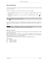
OPERATING INSTRUCTIONS AND SYSTEM DESCRIPTION FOR THE MVCS Series IONTOPHORESIS SYSTEMS With Fast Capacitance Compensation Without Fast Capacitance Compensation VERSION 4.9 npi 2013 npi electronic GmbH, Bauhofring 16, D-71732 Tamm, Germany Phone +49 (0)7141-9730230; Fax: +49 (0)7141-9730240 [email protected]; http://www.npielectronic.com MVCS User Manual ________________________________________________________________________________________________________________ Table of Contents About this Manual ................................................................................................................... 3 1. Safety Regulations .............................................................................................................. 4 2. MVCS Components............................................................................................................ 5 3. System Description ............................................................................................................. 5 3.1. Compensation (Balance) Unit ..................................................................................... 6 3.2. Fast Capacitance Compensation (MVCS-C System) .................................................. 6 3.3. Electrode Resistance Test (MVCS-C System) ............................................................ 7 Electrode resistance test for EJECT channels ............................................................. 7 Electrode resistance test for COMPENSATE channel................................................ 7 4. Description of the Front Panel ............................................................................................ 8 4.1. Front Panel Elements................................................................................................... 9 COMPENSATION Channel (Optional)...................................................................... 12 4.2. Rear Panel Elements.................................................................................................... 13 5. Headstage (MVCS-C System) ............................................................................................ 13 6. Setting up the MVCS / MVCS-C System........................................................................... 14 7. Operation ............................................................................................................................ 15 7.1. Capacity Compensation Tuning Procedure (MVCS-C System) ................................. 15 7.2. Electrode Resistance Test Procedure (MVCS-C System)........................................... 16 8. Literature............................................................................................................................. 18 9. Technical Data .................................................................................................................... 20 ___________________________________________________________________________ version 4.9 page 2 MVCS User Manual ________________________________________________________________________________________________________________ About this Manual This manual should help you setup and use the MVCS-02C system correctly and to perform accurate experiments. Generally, two different versions of the MVCS-02C system are available: System without headstage, REL test and CAPACITY COMPENSATION (MVCS-02C versions) System with headstage, REL test and CAPACITY COMPENSATION (MVCS-C-02C versions) Note: In this manual, the “slow” MVCS-02C version is referred as MVCS, whereas the fast MVCS-C-02C version is referred as MVCS-C. If you are not familiar with the use of instruments for iontophoretic application of substances, please read the manual completely. The experienced user should read at least chapters 1, 4, and 5. Important: Please read chapter 1 carefully! It contains general information about safety regulations and how to handle highly sensitive electronic instruments. Signs and conventions In this manual names of all elements of the front panel are written in capital letters as they appear on the front panel. System components that are shipped in the standard configuration are marked with , optional components with . In some chapters the user is guided step by step through a certain procedure. These steps are marked with . Important information, hints and special precautions are highlighted in gray. Abbreviations IEL REL VEL current at electrode electrode resistance voltage at electrode ___________________________________________________________________________ version 4.9 page 3 MVCS User Manual ________________________________________________________________________________________________________________ 1. Safety Regulations VERY IMPORTANT: Instruments and components supplied by npi electronic are NOT intended for clinical use or medical purposes (e.g. for diagnosis or treatment of humans) or for any other life-supporting system. npi electronic disclaims any warranties for such purpose. Equipment supplied by npi electronic must be operated only by selected, trained and adequately instructed personnel. For details please consult the GENERAL TERMS OF DELIVERY AND CONDITIONS OF BUSINESS of npi electronic, D-71732 Tamm, Germany. 1) GENERAL: This system is designed for use in scientific laboratories and must be operated by trained staff only. General safety regulations for operating electrical devices should be followed. 2) AC MAINS CONNECTION: While working with the npi systems, always adhere to the appropriate safety measures for handling electronic devices. Before using any device, please read manuals and instructions carefully. The device is to be operated only at 115/230 Volt 60/50 Hz AC. Please check for appropriate line voltage before connecting any system to mains. Always use a three-wire line cord and a mains power-plug with a protection contact connected to ground (protective earth). Before opening the cabinet, unplug the instrument. Unplug the instrument when replacing the fuse or changing line voltage. Replace fuse only with an appropriate specified type. 3) STATIC ELECTRICITY: Electronic equipment is sensitive to static discharges. Some devices such as sensor inputs are equipped with very sensitive FET amplifiers, which can be damaged by electrostatic charge and must therefore be handled with care. Electrostatic discharge can be avoided by touching a grounded metal surface when changing or adjusting sensors. Always turn power off when adding or removing modules, connecting or disconnecting sensors, headstages or other components from the instrument or 19” cabinet. 4) TEMPERATURE DRIFT / WARM-UP TIME: All analog electronic systems are sensitive to temperature changes. Therefore, all electronic instruments containing analog circuits should be used only in a warmed-up condition (i.e. after internal temperature has reached steady-state values). In most cases a warm-up period of 20-30 minutes is sufficient. 5) HANDLING: Please protect the device from moisture, heat, radiation and corrosive chemicals. 6) CURRENT INJECTION HIGH VOLTAGE HEADSTAGE: The current injection headstages have an output compliance of ±45 V up to ±150 V. In addition, some headstages are equipped with a driven shield electrode connector (marked "Driven Shield" on the headstage enclosure). After turning on the instrument do not touch the interior contact or the shield of the electrode plug or of the cable that is connected to this plug. In addition, it is extremely important that the instrument is turned off when changing or adjusting the electrode. ___________________________________________________________________________ version 4.9 page 4 MVCS User Manual ________________________________________________________________________________________________________________ 2. MVCS Components The following items are shipped with a MVCS system: MVCS amplifier Headstage (MVCS-C systems only) GND connector for headstage (2.6 mm, MVCS-C systems only) Electrode cables (“slow” MVCS systems only) Power cord User manual Optional accessories: Electrode holder Electrode adapter with BNC connectors 3. System Description MVCS systems are high-voltage current sources for iontophoresis or other applications, where constant currents in the nano or microampere range are needed. Standard MVCS-02C systems have an output compliance of ±45 V, and can generate currents up to 450 nA into 100 M while high-voltage MVCS systems work with up to ±150 V generating currents up to 1.5 µA into 100 M. MVCS system are available with one or two ejection channels. A one channel version can be upgraded to a second ejection channel or to an additional compensation (balance) channel (see below). The two channel systems are also available with or without a balance channel. Generally, two different versions of MVCS system can be ordered: System without headstage, REL test and CAPACITY COMPENSATION (MVCS-01C or MVCS-02C and MVCS-01 or MVCS-02 versions) Systems with headstage, REL test and CAPACITY COMPENSATION (MVCS-C-01C or MVCS-C-02C and MVCS-C-01 or MVCS-C-02 versions) Note: In this manual the respective two channel version is described. The slow MVCS-02C and MVCS-02 versions are referred as MVCS whereas the fast MVCS-C-02C version is referred as MVCS-C. The operating and display elements of these instruments facilitate the application of drugs in physiological, pharmacological and biochemical studies. All systems allow very fast drug applications in the millisecond range, and even the sub-millisecond range, if equipped with the fast capacitance compensation option. Therefore, these systems can be used to simulate synaptic events (Renger et al., 2001; Cottrell et al., 2000; Liu et al., 1999). ___________________________________________________________________________ version 4.9 page 5 MVCS User Manual ________________________________________________________________________________________________________________ The MVCS systems are available as 19” instruments or as modules for the EPMS-07 modular system. The standard system described here is housed in a 19" rackmount cabinet. The MVCS-02C consists of two independent channels for current ejection and the other, COMPENSATION, is for balancing the applied current automatically. Each ejection channel has digital ten-turn potentiometer for EJECT or RETAINING currents and CAPACITY COMPENSATION. Each injection channel also has a digital display, overrange LEDs and two switches for selection of the operating mode. The COMPENSATION channel has the same controls, but no potentiometer for adjusting current. In fast systems with CAPACITY COMPENSATION (MVCS-C), the injecting electrodes are connected via small SMB or BNC shielded connectors that are mounted to a small headstage avoiding artifacts caused by long cables. Systems for slow, long lasting applications, in the second or minute range (MVCS), need no headstages. In this case, the electrodes are connected by special connectors at the front panel with shielded cables. For EJECT or RETAIN currents modes of operation include manual activation and automatic control by digital TTL signals (HI = EJECT, LO = RETAIN). An automated electrode resistance test mode (MVCS-C) is also available. 3.1. Compensation (Balance) Unit To avoid artifacts caused by iontophoretic drug application, the MVCS-02C systems are available with a compensation unit built in. The compensation signal (inverted sum of current output signals divided by 10), generated internally, is applied to a separate compensation electrode, if the OPERATE mode is selected for the injection channel(s) and COMPENSATE mode is selected for the COMPENSATION channel. 3.2. Fast Capacitance Compensation (MVCS-C System) The MVCS-C iontophoresis instruments have been designed for high-speed application of drugs in electrophysiological experiments. In addition to the standard features of the slow MVCS devices each channel has a capacity compensation circuit and an REL test unit (see chapter 3.3). The capacity compensation circuit is operated by the control marked CAPACITY COMPENSATION. The correct tuning of the capacity compensation is very important if high speed operation in conjunction with high resistance microelectrodes is required. Uncompensated stray capacitances are charged from the iontophoretic current that is supplied by the instrument. Uncompensated stray capacitance therefore slows application. The tuning procedure is described in chapter 7.1. The CAPACITY COMPENSATION control is based on the well-known conventional compensation: stray capacitances around the electrode are compensated by passing amounts of the electrode signal through a small capacitor. The circuit is set so that overshoots are avoided as far as possible. Caution: Just like any feedback circuit, this circuit can cause overshoots or oscillations if it is overcompensated. ___________________________________________________________________________ version 4.9 page 6 MVCS User Manual ________________________________________________________________________________________________________________ 3.3. Electrode Resistance Test (MVCS-C System) MVCS-C systems are equipped with an automatic electrode resistance test facility. By switching the VEL, IEL, REL switch to REL, the value of the electrode resistance is shown on the digital display in M. The electrode resistance test uses current pulses of ±10 nA to measure the electrode resistance. These pulses are monitored at the CURRENT OUTPUT BNC and the voltage response can be seen on the VEL/10 BNC. In this way, changes of electrode resistance can be recorded with a chart recorder or computer based data acquisition system. In addition, the electrode resistance test mode can be used to tune the fast capacity compensation (see chapter 7.1). Electrode resistance test for EJECT channels In SET mode, the resistance inside the headstage (10 M) is monitored. In OPERATE mode, the resistance of the electrode is displayed. No square shaped signals should be applied to INPUT connector of the respective channel. For testing rectification, the EJECT potentiometer or a ramp signal at the INPUT connector should be used instead. Testing of rectification of the electrode is done, e.g. by application of different current levels both, positive and negative to the electrode (using the EJECT potentiometer) and testing the resistance of the electrode. This resistance must not change over the range of current which is used during the experiment. Electrode resistance test for COMPENSATE channel In COMPENSATE or EXTERN mode, the resistance of the electrode is displayed. In OFF mode, the resistance inside the headstage (10 M) is monitored. Important: The CAPACITY COMPENSATION unit must be tuned properly (see chapter 7.1). Otherwise the electrode resistance display may be inaccurate. Tuning capacity compensation can also be done using the pulses of the electrode resistance test. ___________________________________________________________________________ version 4.9 page 7 MVCS User Manual ________________________________________________________________________________________________________________ 4. Description of the Front Panel Figure 1: MVCS-C-02C front panel view (the numbers are related to those in the text below) ___________________________________________________________________________ version 4.9 page 8 MVCS User Manual ________________________________________________________________________________________________________________ 4.1. Front Panel Elements In the following description of the front panel elements, each element has a number that is related to that in Figure 1. The number is followed by the name (in uppercase letters) written on the front panel and the type of the element (in lowercase letters). Then, a short description of the element is given. The front panel can be divided into three functional units: CHANNEL A, CHANNEL B and COMPENSATION CHANNEL Most of the elements are identical for each unit (with identical functions and labels) and therefore, are numbered and described only once (e.g. #12, HEADSTAGE connector that is also present for CHANNEL B and the COMPENSATION CHANNEL). Figure 1 shows the MCVS-C-02C (fast system) with capacity compensation and the automatic electrode resistance test facility. These two features are not present in the MVCS02C (slow system). In the slow system the CAPACITY COMPENSATION potentiometer is not installed and the function of REL is somewhat different (see below). (1) POWER switch Switch to turn POWER on (switch pushed) or off (switch released). (2) CAPACITY COMPENSATION potentiometer Ten-turn control to set amount of compensation of electrode stray capacitance (see also chapter 7.1). (3) V / nA / M LEDs LEDs indicating the unit of the reading of the DISPLAY (4). (4) CHANNEL A display 3 1/2 digit display for the electrode potential in V (XXX.X V), the electrode current in nA (XXXX nA for channels A and B, XX.XX µA for COMPENSATION channel) or the electrode resistance in M (XXXX M, i.e. 0100 correspond to 100 M), selected by toggle switch (10). For the correct value of the electrode resistance display it is necessary to adjust the capacity compensation accurately (see chapter 7.1). ___________________________________________________________________________ version 4.9 page 9 MVCS User Manual ________________________________________________________________________________________________________________ (5) – OVER + LEDS LEDs indicating that the current source is out of linear range or that the electrode voltage / current is 10% below the maximum output voltage / current. (6) 1 µA / 100 nA switch Two position switch to select the range of the eject current (maximal 1 µA or maximal 100 nA). (7) EJECT potentiometer Ten-turn control to set the EJECT current. The maximal EJECT current is selected by switch (6). (8) VEL/10 connector BNC connector monitoring the electrode potential divided by 10. Normally used to monitor the electrode resistance (see also chapters 3.3 and 7.1). (9) OUTPUT 100 nA/V connector BNC connector monitoring the EJECT or RETAIN current. Calibration for channels A and B: 100 nA / V Calibration for the COMPENSATION channel: 1 µA / V. (The OUTPUT is not isolated from system ground.) (10) VEL, IEL, REL switch 3 position toggle switch to set the mode of display CHANNEL A (4). Position VEL: the electrode potential is displayed. Position IEL: the current flowing through the electrode is displayed. Position REL: the electrode resistance is displayed. REL is obtained by application of current pulses of ±10 nA to the electrode. Important: The REL mode is an option that is only implemented in MVCS-C (fast) systems. In MVCS (slow) systems, the REL position of the switch has the same function as the IEL position (middle position). (11, 21) INPUT connector BNC connector for an auxiliary INPUT. This BNC is directly connected to the output current source and is not isolated from ground. Calibration for channels A and B: 100 nA / V Calibration for the COMPENSATION channel (21): 1 µA / V. Note: The COMPENSATION channel can be used as an additional injection channel by linking an external waveform to this connector and setting switch (19) to EXTERN. ___________________________________________________________________________ version 4.9 page 10 MVCS User Manual ________________________________________________________________________________________________________________ (12) SET / OPERATE switch Two position switch to set the mode of operation. In SET position the electrode outputs are connected to an internally grounded load and no COMPENSATION signal is generated. Thus, the SET position is used to preset the desired values at the EJECT / RETAIN controls on a well defined basis. In the OPERATE position, the current preset at the EJECT / RETAIN controls will flow through the electrode. (13) HEADSTAGE connector 8 pole connector for the HEADSTAGE (MVCS-C systems) or for the cable directly connected to the injecting electrode (MVCS systems). Important: Always turn power off when connecting or disconnecting headstages from the 19" cabinet (see also chapter 1). (14) NORMAL / INVERTED switch Switch to set polarity of EJECT and RETAIN current: NORMAL = EJECT positive, RETAIN = negative. (15) TTL connector Optically isolated BNC connector for external control in the AUTO mode (see also 16). LO = RETAIN, HI = EJECT. (16) EJECT / RETAIN / AUTO switch Switch to select the mode of operation. EJECT: the EJECT current set with (7) is applied to the electrode. RETAIN: the RETAIN current set with (17) is applied to the electrode. AUTO: Operation controlled by a TTL pulse at (15). Remember: Current is applied to the electrode only if switch (12) is set to OPERATE. (17) RETAIN potentiometer Ten-turn control to set the RETAIN current, range 0-100 nA. (18) GROUND connector Banana jack providing system ground (same as GND at the headstage, see chapter 5). This ground is isolated from power ground (PROTECTIVE EARTH, see chapter 4.2) and the TTL INPUT ground. ___________________________________________________________________________ version 4.9 page 11 MVCS User Manual ________________________________________________________________________________________________________________ COMPENSATION Channel (Optional) (19) COMPENSATE / OFF / EXTERN switch Switch to select the operation mode of the COMPENSATION channel. COMPENSATE: The inverted sum of channels A and B is applied to the electrode. OFF: No current is applied to the electrode. EXTERN: The output current source is connected directly to INPUT BNC (21). In this mode the COMPENSATION channel can be used as an additional injection channel. If, for example, 1 V is connected at (21), an injection current of 1 µA is applied to the electrode connected to the COMPENSATION channel. (20) COMPENSATION INPUT BNC connector for an additional COMPENSATION current. This INPUT can be used to generate COMPENSATION current for two MVCS or MVCS-C systems using only one compensation electrode. Suppose one has two MVCS or MVCS-C systems, system 1 and system 2. The COMPENSATION OUTPUT (22) of the system 2 (without compensation electrode) can be fed into the COMPENSATION INPUT of system 1 (with compensation electrode). With switch (19) in COMPENSATE position (both systems) the current flowing through the compensation electrode connected to system 1 is then the sum of both COMPENSATION channels. Thus, the current of all injection electrodes are balanced with only one compensation electrode. (21) INPUT 1µA/V connector BNC connector for connecting an external voltage for using the COMPENSATION channel as an additional injection channel (see also 19). Calibration is 1 µA / V. (22) OUTPUT 1µA/V connector BNC connector providing a voltage proportional to the COMPENSATION current (see also 9) . This voltage can be used for monitoring the COMPENSATION current or for connecting to a second system (see also 20 and 21). Calibration is 1 µA / V. ___________________________________________________________________________ version 4.9 page 12 MVCS User Manual ________________________________________________________________________________________________________________ 4.2. Rear Panel Elements POWER / FUSE / LINE VOLTAGE SELECTOR The power cord is connected by a standardized coupling which comprises also the fuse, voltage selector and a line filter. With 230V AC the fuse must be 0.4A (slow), with 115V AC it must be 0.8A (slow). Caution: Always use a three-wire line cord and a mains power-plug with a protection contact connected to ground. Before opening the cabinet unplug the instrument. Unplug the instrument also when replacing the fuse or changing line voltage. Replace fuse only by appropriate specified type (see also chapter 1). GROUND / PROTECTIVE EARTH CONNECTORS In order to avoid ground loops, the internal zero (ground) signal of the instrument is not connected to the mains ground and the cabinet. The cabinet and mains ground are connected to the green/yellow connector, the internal ground is connected to the yellow connector. See also GND connector (chapter 4.1 and chapter 5). 5. Headstage (MVCS-C System) The headstage is housed in a small box that can be mounted directly onto a micromanipulator. It is connected to the main amplifier by means of a shielded flexible cable and a multi-pole connector. Figure 2: MVCS-C-02C headstage (for channel A) 1 2 3 4 5 PEL: BNC connector for the electrode holder, grounded shield CHANNEL indicator: marker show for which CHANNEL the headstage is configured, in the example shown for CHANNEL A (see also hint below) OPERATE LED: indicates that injection takes place GND: ground connector holding bar and headstage cable to amplifier (mounting plate or dovetail on request) GND (GROUND) connector The bath (or reference) of the recording chamber is connected to GND. This is the ”lowest” signal level in the recording system, i.e. all signals are related to this signal. This connector must be connected to the ground signal of the recording amplifier / chamber. ___________________________________________________________________________ version 4.9 page 13 MVCS User Manual ________________________________________________________________________________________________________________ PEL In order to avoid disturbances on the recording amplifier, the microelectrode holder is connected via a BNC connector with a grounded shield. Caution: The current injection headstages have an output compliance of ±45 V or ±150 V. In addition, all headstages are equipped with very sensitive FET amplifiers that can be damaged with electrostatic charge and must therefore be handled with care (see also chapter 1. Very Important: Always turn power off when connecting or disconnecting headstages from the 19" cabinet. For changing electrodes it is sufficient to switch the respective channel to SET mode. Also very important: Each headstage is adjusted for a specific channel and instrument. They are labeled A, B, C and D for the EJECT channels, and COMP for the COMPENSATION channel. Please do not exchange headstages for a respective instrument or between different MVCS instruments. Systems for slow, long lasting applications (in the second or minute range) need no headstages (MVCS systems). In these systems the electrodes are connected from special connectors on the front panel with shielded cables: Pin 2: white/blue wire = ground Pin 5: yellow/red wire = electrode 6. Setting up the MVCS / MVCS-C System The following steps should help you set up the MVCS / MVCS-C system correctly. Always adhere to the appropriate safety measures (see chapter 1). After unpacking, the MVCS / MVCS-C system is attached to the setup by assembling the electrical connections. Electrical connections Turn POWER off. Plug the instrument into a grounded outlet. MVCS: Connect your injection- and COMPENSATION electrodes to the special connectors with shielded cables at the front panel. Pin 2: white/blue wire = ground Pin 5: yellow/red wire = electrode MVCS-C: Connect the headstages to the HEADSTAGE connectors (#13, Figure 1) at the front panel. If the recording chamber is not grounded, connect GND of the headstage (MVCS-C) or GND (#18, Figure 1) to the chamber. Note: System ground is isolated from mains ground. The 19" cabinet is connected to mains ground, headstage enclosures are connected to the internal system ground. MVCS-C: Connect the VEL/10 connectors to an oscilloscope or to a data acquisition system. ___________________________________________________________________________ version 4.9 page 14 MVCS User Manual ________________________________________________________________________________________________________________ If you intend to control the MVCS/MVCS-C system externally (e.g. by a computer) connect the gating waveform to TTL (#15, Figure 1), the stimulus waveform to INPUT (#11, Figure 1) and the current OUTPUT (#9, Figure 1) to the analog input of the data acquisition system. 7. Operation MVCS/MVCS-C systems are housed in standard 19" rackmount cabinets. Each system is composed of two independent channels marked A and B and a COMPENSATION CHANNEL. Each channel has an auxiliary analog input and an output that monitors the current flowing through the electrode. Each channel is equipped with a digital display and two overload LEDs. All numbered items refer to Figure 1, page 8, in the following discussion. The Systems can be operated manually by means of a toggle switch on the front panel (#16) or by an external digital pulse (TTL) connected to #15. Turn CAPACITY COMPENSATION (#2) for all channels to less than 1 to avoid oscillations. Turn POWER on. Set the operation mode of all channels to SET using switch #12 to disable current output. Set the EJECT and/or RETAIN current amplitude to the desired values using #7 and #17. MVCS-C: First, compensate the stray capacitances of the electrodes (see chapter 7.1) and second, check the electrode resistances by switching #10 to REL. (see also chapter 3.3 and 7.2) Important: The values of the ELECTRODE RESISTANCE are accurate only if the capacitances of the electrodes are compensated properly. Put the injection- and compensation electrodes to the desired position. Start iontophoresis either manually by setting switch #16 to EJECT and switch #12 to OPERATE or remotely by setting switch #16 to AUTO and applying a TTL pulse to #15. 7.1. Capacity Compensation Tuning Procedure (MVCS-C System) The tuning of the capacity compensation controls is performed with the help of the electrode potential monitor BNC marked VEL/10 (#8) and square pulses applied to the electrode. This pulse can originate from the built-in ELECTRODE RESISTANCE TEST circuit or from an external signal source. The pulses generated internally by the ELECTRODE RESISTANCE test unit have an amplitude of 10 nA. ___________________________________________________________________________ version 4.9 page 15 MVCS User Manual ________________________________________________________________________________________________________________ The tuning must be performed with the electrode in the bath immersed to the maximal depth required during the experiment. Square pulses (positive and negative) of a few nA and 0.110 ms duration are applied to one of the INPUT BNCs (#11) or by activating the ELECTRODE RESISTANCE test unit (#10). The signals from the VEL/10 and CURRENT OUTPUT BNCs (#9) are monitored on an oscilloscope. The SET / OPERATE switch (#12) must be in OPERATE position. The CAPACITY COMPENSATION control (#2) is turned on clockwise until the signal at the VEL/10 BNC is as square as possible (see Figure 3). The highest speed is obtained with a small overshoot (theoretically 4.3 %). The CAPACITY COMPENSATION control is based on the well-known conventional compensation: stray capacitances around the electrode are compensated by passing amounts of the electrode signal through a small capacitor. The circuit is designed to minimize oscillations. Caution: As in any feedback circuit, this circuit can cause overshoots or oscillations, if it is overcompensated. 7.2. Electrode Resistance Test Procedure (MVCS-C System) MVCS-C systems have an electrode resistance test unit built-in. It works by application of rectangular current pulses (±10 nA ) to the electrode. This will cause an voltage drop at the electrode which is proportional to the electrode resistance. This voltage drop is measured, the resulting electrode resistance calculated and shown at the digital display (#4). Set switch #12 to OPERATE. Immerse the electrode into the bath and compensate for stray capacities (see chapter 7.1 above). Note: If #12 is switched to SET the internal resistor of 10 M is measured and displayed. If a different value is shown (within a tolerance of 10%) it is likely the amplifier or the headstage is damaged. Please contact npi electronic in this case. Set VEL, IEL, REL switch to REL. The resistance of the electrode is shown at display #4. Important: The electrode resistance is displayed correctly only if the electrode capacity is compensated accurately! Note: The electrode resistance test is functional also if a iontophoresis current is generated. This feature can be used to test the resistance at different current levels. For testing rectification, the EJECT potentiometer or a ramp signal at the INPUT connector can be used for setting a current level. Testing of rectification of the electrode is done, e.g. by application of different current levels both, positive and negative to the electrode (using the EJECT potentiometer) and testing the resistance of the electrode. If the resistance changes at a certain level the electrode rectifies and should not be used for application of currents above or below this level, i.e. the resistance must not change over the range of current which is used during the experiment. ___________________________________________________________________________ version 4.9 page 16 MVCS User Manual ________________________________________________________________________________________________________________ Figure 3: Capacity compensation of the electrode ___________________________________________________________________________ version 4.9 page 17 MVCS User Manual ________________________________________________________________________________________________________________ 8. Literature Iontophoresis and drug application during single electrode voltage clamp experiments Richter, D.W., Pierrefiche, O., Lalley, P.M. and H.R. Polder (1996) Voltage-clamp analysis of neurons within deep layers of the brain. J. Neurosci. Methods, 67:121-131 Iontophoretic labeling of cells Varvel NH, Grathwohl SA, Baumann F, Liebig C, Bosch A, Brawek B, Thal DR, Charo IF, Heppner FL, Aguzzi A, Garaschuk O, Ransohoff RM, Jucker M. (2012) Microglial repopulation model reveals a robust homeostatic process for replacing CNS myeloid cells. Proc Natl Acad Sci U S A,109:18150-5. Fast capacity compensation / Simulation of synaptic events Behrends, J. C., Lambert, J. D. C. and K. Jensen (2002) Repetitive activation of postsynaptic GABAA receptors by rapid, focal agonist application onto intact rat striatal neurones in vitro, Pflügers Arch 443: 707–712 Cottrell, J.R., Dube, G.R., Egles, C. and G. Liu (2000) Distribution, Density, and Clustering of Functional Glutamate Receptors Before and After Synaptogenesis in Hippocampal Neurons. J Neurophysiol. 84:1573-1587 Heine, M., Groc, L., Frischknecht, R., Beique, J. C., Lounis, B., Rumbaugh, G., Huganir, R. L., Cognet, L., & Choquet, D. (2008). Surface mobility of postsynaptic AMPARs tunes synaptic transmission. Science. 320, 201-205. Heine, M., Thoumine, O., Mondin, M., Tessier, B., Giannone, G., & Choquet, D. (2008). Activity-independent and subunit-specific recruitment of functional AMPA receptors at neurexin/neuroligin contacts. Proc.Natl.Acad.Sci.U.S.A. 105, 20947-20952. Li, Y., Krupa, B., Kang, J. S., Bolshakov, V. Y., & Liu, G. (2009). Glycine Site of NMDA Receptor Serves as a Spatiotemporal Detector of Synaptic Activity Patterns. J Neurophysiol. 102, 578-589. Liu, G., Choi, S. and R.W. Tsien (1999) Variability of Neurotransmitter Concentration and Nonsaturation of Postsynaptic AMPA Receptors at Synapses in Hippocampal Cultures and Slices, Neuron, 22:395–409 Murnick, J. G., Dubé, G., Krupa, B. and Liu, G. (2002) High-resolution iontophoresis for single-synapse stimulation. J.Neurosci.Meth. 116, 65-75. Müller C, Beck H, Coulter D, Remy S. (2012) Inhibitory control of linear and supralinear dendritic excitation in CA1 pyramidal neurons. Neuron, 75:851-64. Renger J.J., Egles, C. and G. Liu (2001) A Developmental Switch in Neurotransmitter Flux Enhances Synaptic Efficacy by Affecting AMPA Receptor Activation. Neuron, 29:469– 484 Slutsky, I., Sadeghpour, S., Li, B., & Liu, G. (2004). Enhancement of synaptic plasticity through chronically reduced Ca2+ flux during uncorrelated activity. Neuron. 44, 835-849. Tang, Y.P, E. Shimizu, G. R. Dube, C. Rampon, G. A. Kerchner, M. Zhuo, G. Liu and J. Z. Tsien (1999) Genetic enhancement of learning and memory in mice, Nature, 401:63-69 ___________________________________________________________________________ version 4.9 page 18 MVCS User Manual ________________________________________________________________________________________________________________ General methods Lalley, P.M. (1999) Microiontophoresis and Pressure Ejection, in: U. Windhorst, and H. Johansson (eds) Modern Techniques in Neuroscience Research, Springer, Berlin Heidelberg, New York (highly recommended) Ogden, D. (ed.) (1994): Microelectrode Techniques, The Company of Biologists LTD, Cambridge Purves, R.D. (1981): Microelectrode Methods for Intracellular Recording and Iontophoresis. London, Academic Press Roberts, M.H.T. and T. Gould (1993) Iontophoresis in the mammalian central nervous system, in D.I. Wallis (ed.), Electrophysiology, A Practical Approach, Oxford University Press, Oxford Zieglgänsberger, W. (1992) Arrays for Microiontophoresis, in Kettenmann, H & Grantyn, R. (eds.) Practical Electrophysiological Methods. Wiley Liss, New York ___________________________________________________________________________ version 4.9 page 19 MVCS User Manual ________________________________________________________________________________________________________________ 9. Technical Data floating current source, output impedance >1012 450 nA [1.5 µA] into 100 M load current: XXXX nA, balance: XX.XX µA, voltage: XXX.X V, Rel: XXXX M, displayed value is set by a three position toggle switch, separate displays for each channel Over LEDs: activated 10% below maximum current / voltage Eject: ten-turn control, range: 100 nA or 1 µA, selected by switch Minimum pulse duration: 100 µs Retain: ten-turn control, maximum 100 nA Capacity compensation: ten-turn control, range 0-30 pF Output current polarity: selected by INVERTED/NORMAL toggle switch Modes of operation: set by two toggle switches EJECT/RETAIN/AUTO switch enables manual or TTL controlled operation SET/OPERATE switch connects automatically electrode outputs to ground (SET position) TTL input (AUTO mode): LO = RETAIN, HI = EJECT, isolated, Rin >5 k Analog input: sensitivity 100 nA / V, Rin >100 k, range ±10 V Current monitor: sensitivity 100 nA / V, Rout = 50 , not isolated Voltage monitor: VEL / 10, Rout = 50 , not isolated Balance output: inverted sum of all injection currents, sensitivity 1 µA / V Power requirements: 230 V / 115 V, 50 Hz / 60 Hz AC, 50W, fuse 0.4A / 0.8A, slow Electrode output: Maximum current: Display: Output connector pins and cable colors: (for systems without headstage) Pin 2: white/blue wire = ground Pin 5: yellow/red wire = electrode Dimensions Amplifier: Headstage: standard 19" rackmount cabinet 19” (483 mm), 10” (250 mm), 3.5” (88 mm) approx. 65x25x25 mm ___________________________________________________________________________ version 4.9 page 20