1
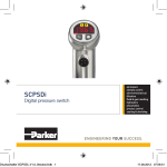
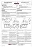
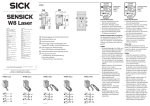
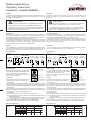
Bedienungsanleitung
Operating Instructions
Verstärker / Amplifier ISG-A1...
Einleitung
Introduction
Verstärker werden als Bestandteil eines übergeordneten Gesamtsystems zur Erfassung von Objekten eingesetzt. Sie können nur mit einem Sender IT... und einem
Empfänger IR... betrieben werden.
Amplifiers are used as the components of a higher-level overall system for the
detection of objects. They can only operate with one Transmitter IT... and one
Receiver IR...
Sicherheitshinweise
Safety instructions
Der Einsatz von Infrarot-Verstärkern ISG-A... ist nicht zulässig für Anwendungen,
bei denen die Sicherheit von Personen von der Gerätefunktion abhängig ist.
The operation of infrared amplifier ISG-A... is not authorized for applications
where the safety of a person depends on the function of the device.
Der Betreiber des übergeordneten Systems, z.B. einer Maschinenanlage,
ist für die Einhaltung der nationalen und internationalen Sicherheits- und
Unfallverhütungsvorschriften verantwortlich.
The operator of the higher-level overall system, e.g. a machine installation,
is responsible for complying with the national and international safety and
accident prevention regulations which apply to the specific use.
Arbeitsweise
Principle of operation
Die Geräte der Serie ISG-A1... sind 1-Kanal-Automatik-Verstärker bei denen kein
Einstellen oder Nachstellen erforderlich ist. Sie erkennen beim Einschalten den
Montageabstand, pegeln sich sekundenschnell optimal ein und regeln auf das System einwirkende Störeinflüsse permanent und zu 100 % aus.
Der Verstärker arbeitet mit moduliertem Infrarotlicht, wodurch eine hohe Sicherheit
gegen Fremdlicht erreicht wird. Die Schaltung ist so ausgelegt, daß nur Signale
richtiger Frequenz und Phasenlage erkannt werden. Dadurch ist eine Beeinflussung durch andere Lichtschranken nahezu ausgeschlossen.
The devices of the series ISG-A1... are 1-channel automatic amplifiers, which need
no adjustments. After switching on the voltage supply, the eyes detect the range
between them and adjust the transmit power to the optimum level.
The amplifier works with modulated infrared light which provides high immunity to
ambient light. The electronic circuits are designed to detect only those signals with
the correct frequency and phase relation. This almost completely excludes
interference from other light barriers.
Montage
Installation
Die Verstärker sind für eine schnelle Montage und Demontage konzipiert und besitzen daher einen Steckanschluß. Um eine sichere Funktion zu garantieren und eine
Beschädigung des Gerätes zu vermeiden immer einen Stecksockel benutzen.
The device includes a plug for simple installation. As a safe operating procedure
and to avoid damaging the device, use an 11-PIN socket.
Anschlußschema
Wiring diagram
ISG-A1x3
Betriebsspannung
Supply voltage
ISG-A1x4
Transistorausgang
Transistor output
Sender Empfänger
Transmitter Receiver
Alarmausgang Test-Eingang
Grundleistung
Test input
Alarm output
Basic transmit level
pnp
(max. 30 VDC)
Rot/
Red
7
Schwarz/
Black
7
Gelb/
Yellow
offen/open = inaktiv/inactive
0V
= aktiv/active
offen/open = Low 1
0V
= Low 2
Sender Empfänger
Transmitter Receiver
Relais
Relay
Betriebsspannung
Supply voltage
COM
Schirm/
Shield
7
7
NO
NC
7
Schwarz/
Black
Gelb/
Yellow
Test-Eingang
Test input
pnp
Grundleistung
Basic transmit level
offen/open = inaktiv/inactive
0V
= aktiv/active
offen/open = Low 1
0V
= Low 2
Schirm/
Shield
7
7
Ground
NPN
Rot/
Red
Alarmausgang
Alarm output
7
Ground
außer ISG-A113
except ISG-A113
PNP
nur ISG-A113
only ISG-A113
außer ISG-A114
except ISG-A114
24 VDC
Betriebsspannung
DIP-Schalter
Die Betriebsspannungsangabe ist in den letzten
Zwei oder Drei Nummern der Gerätebezeichnung
enthalten (siehe rückseitiges Typenschild).
Bei 24 V DC ein passend dimensioniertes UL
Class 2 Netzteil verwenden.
IR-Amplifier
Automatic
Die Funktionen sind mit dem DIP-Schalter auf der
Geräterückseite einzustellen. (Außer ISG-A11...).
ISG-A124/230VAC
8IG 421 241
Supply voltage
Stecker
The supply voltage is the last two or three numbers
of the part number. On the bottom of the amplifier
is the type plate with the part number.
24Vdc to be provided by a suitably rated UL Listed
Class 2 power supply.
Typenschild
Function
Betriebsspannung
The functions are selectable by DIP-switches on
the bottom of the amplifier (except ISG-A11...).
(außer ISG-A11...)
Funktionen
nur ISG-A114
only ISG-A114
24 VDC
zum Beispiel: 230VAC
DIP-switch
(except ISG-A11...)
Plug
Type plate
IR-Amplifier
Automatic
ISG-A124/230VAC
Supply voltage
8IG 421 241
for example: 230VAC
- Schaltfunktion
Die Schaltfunktion beschreibt das Verhalten des Schaltausganges beim Unterbrechen des Infrarotstrahls. Bei Dunkelschaltung erfolgt bei unterbrochener Lichtstrecke
ein Ausgangssignal. In Hellschaltung erfolgt bei freier Lichtstrecke ein Ausgangssignal
- Switching mode
The switching mode determines the output behavior upon interruption of the infrared
beam. When the amplifier is set to dark mode, there is a output signal as long as the
beam is broken. In light mode, there is an output signal when the beam is present.
- Sendefrequenz
Bei der Montage mehrerer Sensoren dicht nebeneinander, ist ein Betrieb der Verstärker bei verschiedenen Sendefrequenzen noch möglich. Jeder Verstärker wertet
nur das Signal mit der eigenen Sendefrequenz aus.
- Transmit frequency
The transmit frequency means the modulation frequency at which the amplifier works.
If more than one sensor head is mounted side by side, the amplifier must be set to
different frequencies.
- Grundleistung
Die Grundleistung gibt an, wie der Verstärker die Leistung regelt.
Low1: Der Sendestrom wird auf den optimalen Wert für die Strecke eingestellt (empfindlichste Einstellung).
Low2: Wie Low1, aber der Verstärker ist unempfindlicher (benötigt eine höhere
Streckendämpfung, um eine Änderung am Schaltausgang zu erzeugen).
High1: Der Sendestrom beträgt mindestens 50 % des Maximalwertes.
High2: Der Sendestrom beträgt mindestens 90 % des Maximalwertes.
- Basic transmit level
The basic transmit level is the minimum transmit power level on an infrared amplifier
Low1: The transmit power level is always set to the optimal value for constant high
switching sensitivity.
Low2: The amplifier works like low1 basic transmit level but the device is less sensitive.
High1: The transmit power is always at least 50 % of the maximum power level.
High2: The transmit power is always at least 90 % of the maximum power level.
DIP-Schaltereinstellung
ISG-A12...,
ISG-A13...
DIP switch setting
ISG-A14...
1
2
Grundleistung
High 2
High 1
Low 2
Low 1
ON
ON
OFF
OFF
ON
OFF
ON
OFF
3
4
Schaltfunktion
Sendefrequenz
1
dunkel
ON
4,1 kHz
ON
hell
OFF
3,7 kHz
OFF
2
Basic transmit power
High 2
High 1
Low 2
Low 1
ON
ON
OFF
OFF
ON
OFF
ON
OFF
3
4
Switching mode
Transmit frequenz
dark
ON
4,1 kHz
ON
light
OFF
3,7 kHz
OFF
Anzeigen und Bedienelemente:
Zustandsanzeige (Schaltausgang)
Empfindlichkeitsanzeige
Alarmanzeige
Anzeige für gewählte
Sendefrequenz
H6, H7: Anzeige für gewählte
Grundleistung
P1:
Einschaltverzögerung
P2:
Ausschaltverzögerung
S1:
Test/Reset Taster
H1
H2
H3
H1:
H2:
H3:
H4, H5:
OUTPUTSTATUS
ISG-A13...
ERROR
TRANSM. FAIL
TRANSMIT
CHANNEL
RECEIV. FAIL
NORMAL
TEACH
LOW 1
LOW 2
LEVEL 1
LEVEL 2
TEST MODE
S1
ISG-A12...
SEARCH
ALARM
H4
H5
H6
H7
ISG-A11...
NO SIGNAL
SIGN. QUAL.
AUTOMATICFUNCTION
TEACH IN
RESET
ISG-A14...
Display contents:
H1:
H2:
H3:
H4, H5:
Switching indicator
Automatic level display
Alarm display
Display for selected Transmit
frequency
H6, H7: Display for selected Basic
transmit level
P1:
Switching on delay
P2:
Switching off delay
S1:
Test/reset button
Inbetriebnahme
Operating procedure
Verstärker in den Sockel stecken und die Betriebsspannung einschalten. Das Gerät
ist im Normalbetrieb. Aus dem Normalbetrieb gelangt man durch Drücken des Tasters S1 in den Testbetrieb. Ein Drücken des Tasters S1 für 2 Sekunden erzeugt ein
Reset. Sollte nach dem Einschalten die Anzeige H3 leuchten, ist die Sichtverbindung
zwischen Sender und Empfänger unterbrochen.
Place the amplifier into the socket and switch ON the power supply. The device is
in the normal operation mode. From the normal mode, press S1 to enter the test
mode. Pressing S1 for 2 seconds will cause a reset. If the display H3 lit after
switching on the power supply, the contact between the transmitter and receiver is
interrupted.
Normalbetrieb
Bei Sichtverbindung zwischen Sender und Empfänger leuchtet die LED H2. Die
Sendeleistung wird automatisch eingestellt. Verschmutzen die Sensoren langsam,
erhöht der Verstärker die Sendeleistung. Bei 95 % der max. Sendeleistung leuchtet
die Alarmanzeige H3 und der Alarmausgang ist aktiv (24 V DC). Wird der Infrarotstrahl unterbrochen, erlischt die Anzeige H2 und die Sendeleistung bleibt konstant
bis die Unterbrechung beseitigt ist. Mit dem Potentiometer P1 und P2 (nur ISG-A13...)
kann die Ein- und Ausschaltverzögerung zwischen 0...10 s eingestellt werden.
Normal operation mode
If there is contact between transmitter and receiver the LED H2 lights. The transmit
power will be turned automatically to the optimum. If the sensor heads are blocked
slowly the amplifier raises the transmit power. At 95 % of the max. transmit power,
the alarm display H3 lights and the alarm output is active (24 V DC). If the infrared
beam is interrupted, the display H2 is OFF and the transmit power level will be
constant until the infrared beam is clear again. With the P1 und P2 (only ISG-A13...)
is the switching ON and OFF delay adjustable between 0...10 s.
Testbetrieb (außer ISG-A11...)
Die Verstärker überprüfen im Testbetrieb die Sensoren und die Streckenqualität.
a) Streckenqualität (Signalstärke)
Die Anzeige H2 blinkt zwischen 1 und 10 mal. Je öfter die Anzeige blinkt, desto
besser ist das empfangene Signal.
b) Fehler
Die Anzeige H3 blinkt rot. Weitere Anzeigen beschreiben den Fehler genauer:
H1 blinkt - kein Signal
Sensoren sind in Ordnung. Die Sichtverbindung ist unterbrochen.
H4 blinkt - Fehler Sender
wie H3:
Der elektrische Widerstand ist zu hoch (kein Sender).
schneller als H3: Der elektrische Widerstand ist zu niedrig (Kurzschluß).
H5 blinkt - Fehler Empfänger
wie H3:
Der elektrische Widerstand ist zu hoch (kein Empfänger).
schneller als H3: Der elektrische Widerstand ist zu niedrig (Kurzschluß).
Test mode (except ISG-A11...)
In the test mode the amplifier checks the sensor heads and the signal quality.
a) Signal strength
The display H2 flashes between 1 and 10 times. The flashes are proportional to the
received signal.
b) Error
The display H3 flashes red. Another LED describes the error exactly:
H1 flashes - no signal
The Sensor heads are operational. The transmit signal can not be received.
H4 flashes - transmitter fail
like H3:
The resistance is too high (no transmitter).
faster than H3: The resistance is too low (short circuit).
H5 flashes - receiver fail
like H3:
The resistance is too high (no receiver).
faster than H3: The resistance is too low (short circuit).
Teachbetrieb (nur ISG-A14...)
Mit dem Teachbetrieb werden die Schaltpunkte vom Relais oder Transistorausgang
programmiert. Folgende Teachversionen sind möglich:
Level1: Objekt soll erkannt werden
Level2: Objekt soll nicht erkannt werden
Teach mode (only ISG-A14...)
With the teach mode, the switching point from the relay or transistor output can be
programmed. Two teach modes are possible:
Level1: The object shoud be recognized
Level2: The object shouldn’t be recognized
Objekt zwischen die Sensoren stellen und Taster S1 kurz Drücken. Anzeige H2
blinkt. Wenn der Teachvorgang erfolgreich abgeschlossen ist, leuchtet H2 konstant.
Put the object between the Sensor heads and push the button S1. The display H2
flashes. If the teach mode completes successful, the display H2 lights constant.
Schaltlogik / Switching logic
Maßzeichnungen / Dimensions
Alle technischen Angaben beziehen sich
auf den Stand 01/2009, Änderungen bleiben vorbehalten.
OI090102DE/EN
hell /
light
24 V DC
dunkel /
dark
0
hell /
light
0
dunkel /
dark
24 V DC
All technical specifications refer to the
state of the art 01/2009, they are subject
to modifications.
76,5
Sichtverbindung / Beam status
SchaltZustandsRelais- Transistorfunktion / anzeige / ausgang / ausgang /
Switching- Switching
Relay
Transistormode
indicator
output
output
40
mm
Hersteller / Manufacturer:
Pantron Instruments GmbH
Süllbergstraße 3-5
D 31162 Bad Salzdetfurth
Tel.
Fax
e-mail
Internet
++49 (0) 50 63 / 95 91-0
++49 (0) 50 63 / 95 91-55
[email protected]
www.pantron.de