1
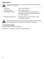
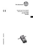
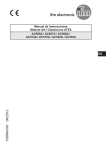
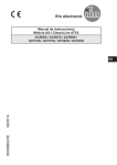
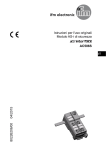
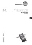
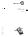
Operating instructions
7390737 / 00
07 / 2008
ClassicLine module
AC5245
UK
Contents
1 Functions and features����������������������������������������������������������������� 3
2 Operating and display elements�������������������������������������������������� 3
3 Installation������������������������������������������������������������������������������������ 4
4 Addressing������������������������������������������������������������������������������������ 9
4.1 Addressing with the AC1144 addressing unit���������������������������� 9
5 Electrical connection�������������������������������������������������������������������� 9
7 Technical data����������������������������������������������������������������������������� 10
1 Functions and features
• Maximum number of modules per master: 62
• AS-interface version 3.0, downward compatible
2 Operating and display elements
5
1
UK
4
3
2
1�
2�
3�
4�
5�
addressing interface
4 M12 sockets
LED
labels
LED PWR
Scale drawing
3 Installation
1
Alignment of the flat cable on
delivery
Carefully place the yellow AS-i flat
cable into the profile slot.
2
Mount the upper part.
3
Lock the unit.
With the supplied lower part the
flat cable can be aligned in three
directions.
For the requested direction place the
flat cable guide (1) accordingly.
UK
A
Settings at the lower part
Select the position 1, 2 or 3 depending
on the requested flat cable alignment
(→).
A = factory setting
B
C
Settings at the upper part
Then set the selected position at the
upper part. To do so, turn the triangle
to the corresponding number (fig. D1
and D2).
UK
D1
Use a tool, e.g. a screwdriver (figure
D1) or the yellow / black flat cable
guide (figure D2).
D2
Open the unit
Open the unit using a tool as shown
(e.g. screwdriver).
Take care in laying the AS-i flat cable,
the flat cable should be laid straight for
about 15 cm.
4 Addressing
The address is set to 0 at the factory.
4.1 Addressing with the AC1144 addressing unit
When mounted and wired the module can be addressed with the addressing cable
(E70213) via the integrated addressing interface.
If a slave with the extended addressing mode is used in combination with a master
of the first generation (version 2.0), an address between 1A and 31A must be
assigned to this slave.
4 inputs / AS-i profile S-0.A.E / extended addressing mode: yes
Data bit
Input
Socket
D0
I1
I-1
D1
I2
I-2
D2
I3
I-3
D3
I4
I-4
Inputs
��
�
�����������
�
�
��
5 Electrical connection
Connect the plugs of the sensors to the M12 sockets.
To guarantee protection rating IP 67
• cover the unused sockets with protective caps (E73004)*, tightening torque
0.6...0.8 Nm.
• the flat cable end seal (E70413)* must be used if the module is at the end of
the cable line.
*to be ordered separately
UK
6 Operation
Avoid build-up of dirt and dust on the upper and lower parts so that the locking
mechanism is not affected.
• LED yellow:
• LED PWR green:
• LED FAULT red lights:
• LED FAULT red flashes:
input / output switched
AS-i voltage supply ok
AS-i communication error, slave does not
participate in the "normal" exchange of data,
e.g. slave address 0
peripheral fault, e.g. sensor supply / output
overloaded or shorted
Overload and short circuit of the input supply and the outputs are signalled as peripheral fault to the AS-i master (version 2.1 or higher).
7 Technical data
Technical data and further information at
www.ifm.com --> Select your country --> Data sheet direct
10