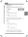
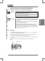
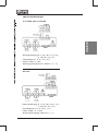
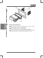
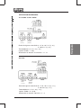
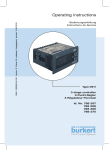
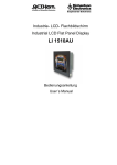
1
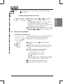
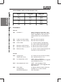
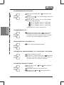
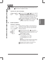
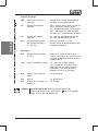
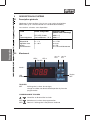
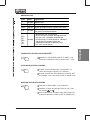
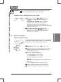
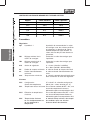
Operating Instructions
Bedienungsanleitung
Instructions de Service
Type 0911
2 stage controller
2-Punkt-Regler
2 Régulateur Ponctuel
Id. No. 788
788
788
788
263
264
265
266
We reserve the right to make technical changes without notice.
Technische Änderungen vorbehalten.
Sous resérve de modification techniques.
© 2004 Bürkert Werke GmbH & Co.
Operating Instructions 0509/03_EU-ml_00804604
TYPE 0911
1
GENERAL INFORMATION ........................................................................................................................ 2
1.1
Symbols ......................................................................................................................................................... 2
1.2
Safety notes ................................................................................................................................................ 2
1.3
Scope of delivery ...................................................................................................................................... 3
1.4
Warranty provisions ............................................................................................................................... 3
2
SYSTEM DESCRIPTION ............................................................................................................................ 4
2.1
General description ................................................................................................................................. 4
2.2
Operation ...................................................................................................................................................... 4
2.3
Before the installation ............................................................................................................................. 7
2.4
Parameters .................................................................................................................................................. 8
2.5
Controlling the loads ............................................................................................................................. 11
3
TECHNICAL DATA ..................................................................................................................................... 12
4
ASSEMBLY, INSTALLATION AND COMMISSIONING .......................................................... 13
4.1
General information regarding the installation and operation ......................................... 13
4.2
Assembly .................................................................................................................................................... 13
4.3
Electrical connections .......................................................................................................................... 14
5
HOT-KEY FUNCTION ................................................................................................................................. 16
6
FACTORY SETTING .................................................................................................................................. 17
7
MAINTENANCE ............................................................................................................................................ 18
8
REPAIR WORK .............................................................................................................................................. 19
8.1
Faults ............................................................................................................................................................. 19
8.2
Ordering table for basic unit/accessories ................................................................................ 20
0911 - 1
english
2-STAGE CONTROLLER
1
GENERAL INFORMATION
1.1
Symbols
The following symbols are used in these operating instructions:
english
marks a work step that must be carried out.
ATTENTION!
NOTE
1.2
indicates information which, if ignored, could lead to a risk to
your health or to the functionality of the device.
indicates important additional information,
tips and recommendations.
Safety notes
Please observe the notes in these operating instructions together with the
conditions of use and permitted data that are specified in the data sheets of
the 0911 controller, so that the device will function perfectly and will have a
long service life.
•
Keep to the standard engineering rules when planning and operating the
device!
•
Installation and maintenance work may only be carried out by specialist
personnel using the correct tools!
•
Observe the current regulations on accident prevention and the safety
regulations for electrical devices during the operation and maintenance of
the device!
•
Comply with the intended usage of the device.
•
Only operate the device with its housing fitted.
•
Before connecting the device, check that the power supply corresponds to
the values printed on the device.
•
Check that the connections are correct before switching on the device.
•
Observe the maximum load of the relay contacts (see technical data).
•
Ensure that all sensors are installed with sufficient separation from voltageconducting lines. This will avoid incorrect temperature readings and will
protect the device from voltage interference at the sensor inputs.
•
For applications in the industrial sector with critical environments, switch an
RC element in parallel (FT1).
•
Always switch off the mains supply before carrying out manipulations on
the system.
•
Take suitable measures to exclude unintended operation and damage by
unauthorised operation!
2 - 0911
Please observe the prescribed environmental conditions with regard to
dampness and temperature limits. Malfunctions cannot be excluded if these
conditions are not complied with.
•
Call in your authorised Bürket sales centre in case of doubt or faulty
functioning.
In the case of the non-observance of these notes or of unauthorised
manipulation of the device, we will accept no liability, and the guarantee on the
device and its accessories will become void!
1.3
Scope of delivery
Immediately after receiving the delivery, ensure that the contents agree with
the scope of the delivery. This includes:
•
1 Type 0911 controller
•
1 set of operating instructions (where required, on a data carrier)
•
1 front seal
•
2 Mounting clamps
In case of discrepancy, please contact our Customer centre immediately:
Bürkert Steuer- und Regelungstechnik
Service-Abteilung
Chr.-Bürkert-Str. 13-17
D-76453 Ingelfingen
Tel. : 07940-10111
or your Bürkert Sales Centre.
1.4
Warranty provisions
Bürkert provideds a guarantee of one year on the correct functioning of the
controller, under the precondition that the device is employed for its intended
use and under compliance with the specified conditions for use.
If the functions of the device are not in order, the respective device will be
repaired free of charge or will be replaced.
ATTENTION!
The warranty only covers the the controller and its components, but does not cover consequential damage of any kind
that could arise from the failure or malfunctioning of the device.
0911 - 3
english
•
2
SYSTEM DESCRIPTION
2.1
General description
english
2-point controller, 74 x 32 mm, with predefinable control function (e.g., heating/
cooling or moisten/dehumidify)
The following models are available:
2.2
Type
Configurable Input
Parameter UDM
(Defined by display unit)
TU
Temperature
controller
PTC, NTC, Pt100
Thermoelements J, K, S
UDM = °C
UDM = °F
AU
Control device with
current / voltage
input
4 ... 20 mA
0 ... 1 V
0 ... 10 V
0 = °C; 1 = °F
2 = % RH
3 = bar
4 = PSI
5 = without units
Operation
LED1
LED 2
updownwards wards
ES LED
Output 1
SET
button
Alarm
LED
BUTTONS
SET
Display of the set-value,
Changing and confirming a default during the programming phase
BUTTON COMBINATIONS
+
Locking and unlocking the keypad
SET+
Selecting the programming level
SET+
Return to the room temperature display
4 - 0911
LED
Mode
Meaning
on
Output active
LED1
blinks
Programming level (blinks together with LED2)
LED2
blinks
Programming level (blinks together with LED1)
on
Energy-saving mode (second set-value) has
been activated by the digital input
on
- Signals an Alarm state
- If you are in the lower programming level
"Pr2", which can only be accessed using
a password, the lighting up of the Alarm LED
signals that the displayed parameters can
also be accessed in the first level Pr1
(without password).
E.S.
Alarm
LED
english
LED MESSAGES
SWITCH DEVICE ON/OFF
Hold the SET button down for at least 4 sec
(only for parameter OnF = yes).
SET-VALUE DISPLAYS
Briefly press the SET button once. The set-value
display appears in the display.
Briefly press the SET button again, or wait 5
seconds in order to display the room temperature.
CHANGE THE SET VALUE
Hold the SET button down for 2 seconds.
Change the set-value within 10 s with the
buttons.
or
You can save the new set-value by briefly pressing
the SET button or by waiting 10 seconds.
0911 - 5
ENTER PROGRAMMING LEVEL
Hold the SET +
seconds
english
Select with
button.
buttons down for at least 3
Pr2 and then confirm with the SET
Enter the password 321 and then confirm with the
SET button.
Enter the „3“ and then 1x SET button
Enter the „2“, and then 1x the SET button
Enter the „1“, and then 1x the SET button
You are now in the Parameter List.
USER LEVEL PR1
Press down the SET +
buttons for 3 seconds.
PR1 contains all the parameters accessible to the
user. The device shows the first parameter that is
available in the user level.
SERVICE LEVEL PR2 (PASSWORD 321)
See: Accessing the programming level.
ADDING/REMOVING PARAMETERS IN THE USER LEVEL „PR1“
Accessing the programming level
The status can be changed with the SET +
buttons.
If a parameter is not visible in the PR1 level, this will
be indicated by an LED point.
CHANGING THE DEFAULT PARAMETERS
Enter a desired value with SET +
or
.
Then confirm with the SET button.
Enter a desired parameter with
6 - 0911
or
.
NOTE
All parameter values can be seen by repeatedly pressing the
SET buttons.
Hold down the buttons
and
for at least 3
seconds. The POF message appears on the
display.
The keyboard is locked. You can only view the
set-value and the minimum and maximum
temperature. The POF message also appears if you
hold down a button for longer than 3 s.
The keyboard will be unlocked if you hold down
and
for 3 s. POn appears in the
the buttons
display for a few seconds.
2.3
Before the installation
PREDEFINE THE SENSOR TYPE
The configurable input type is noted on the controller
label. Please enter this input type if it does not
corresponds to the connected sensor type.
Hold down the SET +
seconds.
button for at least 3
Select the parameter Pbc (sensor type) and then
confirm with the SET button to see the current
default.
Type TU (temperature controller):
J = Thermoelement J; Pt = Pt100;
C = Thermoelement K; Ptc = PTC;
S = Thermoelement S; ntc = NTC
Type AU
(control devices with voltage/current input):
cur = 4...20 mA; 0-1 = 0...1 V; 10 = 0...10 V
Confirm the default with the SET button.
Briefly switch off the power to the device.
0911 - 7
english
LOCKING AND UNLOCKING THE KEYPAD
MEASUREMENT LIMITS FOR THE SENSOR TYPES
english
Sensor
2.4
Lower limit
Upper limit
NTC
-40°C
110°C
PTC
-50°C
150°C
Pt100
-200°C
600°C
TcK
0°C
1300°C
TcJ
0°C
600°C
TcS
0°C
1400°C
Parameters
Control
Hy1
Hysteresis 1
Switch hysteresis of Set-value 1 with
positive or negative values. The default
range is dependent on the input type.
The parameter may not be entered as
zero.
LS1
Lowest set-value setting
Set-value limits for operator
US1
Highest set-value setting
Set-value limits for operator
S1C
control effect
in = inverse (heating, humidification)
dir = direct (cooling, dehumidification)
AC
Minimum switch duration
0...250 sec relay switch-off duration
on
Minimum switch-on period
0...250 sec relay switch-on period
ono
Minimum delay
0...120 min; minimum delay between two
activations of the control relay.
Alarms
ALC
Configuration
Temperature alarm
rE = relative to the set-value (in Kelvin)
Ab = absolute values (in °C)
ALL
Low temperature alarm
If SET - ALL is undershot,
a low temperature alarm will be triggered
after the delay time ALd.
ALU
Over-temperature alarm
If SET + ALU exceeded, a high
temperature alarm will be triggered after
delay time ALd.
ALd
Alarm delay
at temperature
Overshoot/Undershoot
0...999 min; Minimum time in which the
conditions for an alarm situation
must be present.
8 - 0911
Alarms
Hysteresis for the
Limit value alarms
ALL and ALU
Automatic alarm acknowledgement:
With high alarm undershot by
ALU - ALH and with low alarm with
under shooting of ALL + ALH
(0.1 K...upper measurement range)
dAO
Alarm delay at
with Mains ON
0...23.5 hours; suppression of
Alarms after commissioning.
S01
Status of the control relay
with sensor fault
oFF = opened
on = closed
tbA
Status of the control relay
after acknowledgement (by
(any button) in an
alarm situation
oFF = Relay deactivated
on = Relay activated
AS
Configuration of the alarm
relay at an alarm
cL = Terminal 4-5 closed
oP = Terminal 4-6 closed
english
ALH
Measured value display
LCI
Lower analog
Display value
(-1999...1999)
Lower display value for current input
4 mA or with voltage input 1 V
or 10 V (only for inputs 4-20
mA, 0-1V, 0-10 V)
UCI
Upper analog
Display value
(-1999...1999)
Upper display value for current input
20 mA or for voltage input 1 V or 10 V
(only for the 4-20 mA, 0-1V, 0-10 V
inputs)
OPb
calibration of the sensor
regardless of the measurement range
rES
Resolution
in = only whole numbers
dE = also tenths
ce = hundreths
UdM
Units
Display of the units directly in the
illuminated display. Regardless of which
controller type is being used:
see General description
PbC
Type of sensor
Temperature sensor U):
Type of inout
J = Thermoelement „J“; Pt = Pt100;
C = Thermoelement „K“; Ptc = PTC;
S = Thermoelement „S“; ntc = NTC
cur = 4...20 mA; 0-1 = 0...1 V;
10 = 0...10 V
Current / voltage input
(AU)
P3F
Third terminal of a
Pt100 sensor
(if present)
no = Pt100 2-wire wired
yES = Pt100 3-wire wired
0911 - 9
english
Digital inputs
HES
Temperature increase/
Reduction
Set-value is increased/lowered by HES
during the energy saving phase.
i1F
Function of the digital
Input
EAL = external alarm; OFF = unused;
bAL = serious external alarm;
Es = Energy saving mode Start/Stop;
onF = switch the device ON/OFF
externally;
C-H = reverse the control effect
i1P
Polarity of the digital
input
CL: active with closed contact
OP: active with opened contact
did
Alarm delay time
of the digital input
(1...120 min)
For i1F = EAL or i1F = bAL.
The corresponding alarm
display or message then takes place
Miscellaneous
Adr
Serial address RS485
(1...247)
Address for XJ500 recording
system. Identifies the device if it
is linked into a ModBUS-compatible
system.
OnF
Set device to STAND-BY
no = not possible via keyboard
yes = STAND-BY can be activated by
holding down the SET button of at least
4 sec. During a STAND-BY, OFF is
displayed.
Ptb
Number of the parametertable
only read-out value
rEL
Version
only read-out value
Pr2
Display of the parameters in display only
Level Pr2
NOTE
10 - 0911
You can access hidden paramaters by holding down the keys
SET +
for 3 sec in the programming level HY. The message Pr2
appears.
Controlling the loads
CONTROLLER OUTPUT
The control is dependent on the measured temperature (= sensor
temperature). Program the control direction (heating or cooling) with the
parameter S1C.
S1C = dir
S1C = in
Cooling
Heating
SET = Set-value
Hy = Switch hysterisis
COOLING
temperature
SET+HY
SET
t
compressor
ON
t
Parameter S1C = dir; The value HY has been preset to 2 K in the factory.
If the temperature exceeds the value SET + HY, the compressor will be
switched on and will be switched off again when the temperature is below SET.
HEATING
temperature
SET
SET-HY
t
heat
ON
t
Parameter S1C = in; The value HY has been preset to 2 K in the factory.
If the temperature falls below the value SET-HY, the controller output will be
switched on and will be switched off again when SET is exceeded.
0911 - 11
english
2.5
english
3
TECHNICAL DATA
• Housing
ABS, self-extinguishing
• Dimensions
Front 74 x 32 mm, Depth 60 mm
• Assembly
Panel-mounting unit for 29 x 71 mm cutout
• Protection class
IP65 from front, only with front seal RG-C
IP20
• Connections
• Pipe cross-section
Screw terminals
≤ 2.5 mm2
• Auxiliary energy
depending on model
12...24 V AC / DC; ± 10%
230 V AC; ± 10%; 50 / 60 Hz
optional 110 V AC; ± 10%; 50 / 60 Hz
• Power consumption
max. 3 VA
• Display
three digits, red LED, height 12 mm
• Inputs
configurable NTC / PTC or
NTC / PTC / Pt100 / Thermoelement J, K, S
or 4...20 mA / 0...1 V / 0...10 V
• Relay outputs
Changeover 8(3) A, 250 V AC
• Other outputs
acoustic alarm (optional)
• Data memory
EEPROM
• Ambient temperature
0 ... +60°C / +32 ... +140°F
• Storage temperature
-30 ... +85°C / -22 ... +185°F
• Air humidity
20 ... 85% (non-condensing)
• Measurement range
according to sensor
• Resolution
0.1°C or 1°F
• Accuracy at + 25 °C
better than 0.5% of the measurement range
12 - 0911
ASSEMBLY, INSTALLATION AND COMMISSIONING
4.1
General information regarding the installation and operation
ATTENTION!
NOTE
4.2
•
Do not lay cables for inputs next to lines carrying voltage.
•
Avoid heavy vibrations, aggressive gases, heavy soiling
and damp.
•
Before connecting the device, check that the power supply
corresponds to the values shown on the rating plate.
•
Observe the maximum loading of the relay contacts (see
Technical data ).
•
Ensure that you install all sensors with sufficient separation
from lines carrying voltage, in order to avoid incorrect
temperature measurements and to protect the device from
voltage interference over the sensor inputs.
Assembly
The device is designed for panel mounting in a 71 x 29 mm cutout, and is
secured with a mounting clamp.
In order to guarantee the front protection of IP65, a rubber seal must be fitted
behind the mounting frame (optional for RG-C).
Thje ambient temperature form problem-free operation lies in the range from
0 ... +60°C.
Ensure sufficient ventilation through the cooling slots.
Panel
Mounting clamp
0911 - 13
english
4
Mounting frame
english
Panel
Front seal
4.3
Electrical connections
Use cable with a cross-section of max. 2.5 mm2. The device is provided
with the corresponding screw terminals.
Check the auxiliary energy before you connect the power supply
(see Technical data).
Do not load the relay contacts higher than permitted. If necessary, use a
contactor.
14 - 0911
PIN ASSIGNMENT
english
12 V AC/DC or 24 V AC/DC
operating
contacts
(1, 2, 3)
alarm
contacts
(4, 5, 6)
Standard signal input: 0...1 V; 0...10 V = 7(+), 9(-)
4...20 mA = 7(+), 9(-)
Thermoelement J, K, S = 7(+) - 9(-)
sensor: Pt100 = 7 - 9(8)
voltage supply: 24 V AC/DC = 11 - 12
230 V AC
operating
contacts
(1, 2, 3)
alarm
contacts
(4, 5, 6)
Standard signal input: 0...1 V; 0...10 V = 9(+), 11(-)
4...20 mA = 9(+), 11(-)
Thermoelement J, K, S = 9(+) - 11(-)
sensor: Pt100 = 9 - 11(10)
voltage supply: 230 V AC = 7 - 8
0911 - 15
5
HOT-KEY function
DOWNLOAD (HOT-KEY
CONTROL DEVICE)
english
Writing the stored parameter set from the HOT-KEY into the control device:
Switch off the electrical power to the controller, or set it to STAND-BY.
Insert the HOT-KEY up to the stop in the marked position on the controller.
Re-activate the controller.
The default parameters in the HOT-KEY will be automatically written into the
controller. During this time, the message DoL blinks in the display. The
programming procedure is finished after 10 seconds, and normal operation
starts automatically with the new parameter set.
The HOT-KEY can be removed.
The following messages are possible at the end of the data transfer:
end for a correct data transfer
err for a failed data transfer
In this case, briefly switch off the power to the device to repeat the
procedure. If you want to cancel the procedure, simply remove the HOTKEY.
UPLOAD (CONTROL DEVICE HOT-KEY)
Writing the current default parameters of the control device into the HOT-KEY:
Insert the HOT-KEY into the provided position when the controller is
switched on again.
Operate 1x with
. The message uPL can be seen in the display.
Press the SET button in order to start the data transfer. uPL starts to blink.
You can remove the HOT-KEY again after about 10 seconds.
The following messages are possible at the end of ther data transfer:
end for a correct data transfer
err for a failed data transfer
In this case, press the SET button again to repeat the procedure. If you
want to cancel the procedure, remove the HOT-KEY.
16 - 0911
FACTORY SETTING
PA1
Description
Range
Default
PE2
SET
Set-value
LS1 + US1
0
Pr1
HY1
Switch hysterisis 1
dependent on measurement
range
-1
Pr1
LS1
Lowest set-value 1
Lower measurement range +
SET1
min
Pr2
US1
Largest set-value 1
Upper measurement range +
SET1
max
Pr2
S1C
Control effect Output 1
in = inverse; dir = direct
in
Pr2
Ac
Delay time for the relay
0...250 sec
0
Pr2
on
Minimum switch-on time
for a relay
0...250 sec
0
Pr2
ono
Minimum waiting time
between two consecutive
activations of the same
load
0...120 min
0
Pr2
ALC
Alarm limits are absolute
values or related to the
set-value
rE = relative; Ab = absolute
rE
Pr2
ALL
Lower Alarm Limit
(ALC = rE; ALC = Ab)
dependent on measurement
range
10
Pr2
ALU
Upper Alarm Limit
(ALC = rE; ALC = Ab)
dependent on measurement
range
10
Pr2
ALH
Switch hysterisis for
temperature alarms
dependent on measurement
range
2
Pr2
ALd
Alarm delay time during
the operation
0...999 min
15
Pr2
dAO
Alarm delay time after
commissioning
0...23.5 h
1.3
Pr2
So1 Output 1 for sensor error
1
oFF = open; on = closed
oFF
Pr2
tbA
Alarm relay can be
acknowledged
no; yES
yES
Pr2
AS
Polarity of the Alarm
relay
CL...oP
oP
Pr2
LCI3
Lower analog display
value
depending on sensor
var.
Pr2
Parameter
2
Programming level
3
Only for devices with voltage and current input
0911 - 17
english
6
english
1
7
PA1
Description
Range
Default
PE2
UCI3
Upper analog display
value
depending on sensor
var.
Pr2
Opb
Sensor calibration
depending on measurement
range
0
Pr1
rES
Resolution
in = NO; dE = 0.1; cE = 0.01
in
Pr2
UdM
Units
Type TU: °C = °C, °F = °F;
Type AU: 0 = °C, 1 = °F;
2 = RH, 3 = bar, 4 = PS,
5 = without display
var.
Pr1
PbC
Type of sensor
Pt = Pt100; J = tcJ; c = tck;
S = tcS; Ptc = PTC;
ntc = NTC; 0.1 = 0...1 V;
10 = 0...10 V; cur = 0...20 mA
var.
Pr1
P3F
3rd sensor present
no = no; yES = yes
no
Pr2
HES
Energy-saving mode
Down scale / Full scale
0
Pr2
i1F
Configuration of the
digital input
c-H / oFF / off / HES /
EAL / bAL
EAL
Pr2
i1P
Polarity of the digital
input
cL = closed;
oP = open
cL
Pr2
did
Alarm delay of the digital
input
0...120 min
0
Pr2
Adr
Serial address for XJ500
RS485 address
1
Pr2
OnF
Activate Standby
function
no = no; oFF = active
no
Pr2
Ptb
Parameter table
Read value
-
Pr2
rEL
Software version
Read value
-
Pr2
Pr2
Parameter access to Pr2
Read value
321
Pr1
Parameter
2
Programming level
3
Only for devices with voltage and current input
MAINTENANCE
When operated in accordance with the instruction in this handbook, the 0911
controller is maintenance-free.
18 - 0911
8
REPAIR WORK
8.1
Faults
Message
Cause
Effect
PFo
Sensor defective or not
connected
Alarm relay ON; control circuit
according to So1
PFc
Sensor short-circuit
Alarm relay ON; control circuit
according to So1
HA
High temperature alarm
Alarm relay ON; outputs remain
unchanged
LA
Low temperature alarm
Alarm relay ON; outputs remain
unchanged
EAL
Digital input alarm
Outputs remain unchanged
BAL
Serious digital alarm
All control outputs deactivated
STATUS OF THE ALARM RELAY
AS = CL
AS = OP
Device without power
Device status
4 - 6 closed
4 - 6 closed
Normal operation
4 - 6 closed
4 - 6 open
4 - 6 open
4 - 6 closed
Alarm situation during
operation
ACKNOWEDGING ERRORS VIA THE KEYBOARD
Press any button.
The Alarm message remains on the display as long as the alarm conditions
are present. The device then switches to normal operation.
AUTOMATIC ACKNOWLEDGEMENT OF THE ERROR
•
Message PFo and PFc - Room sensor error
After approx. 30 seconds or once the error has been cleared, the
message will be acknowledged automatically. Check the connections
before any replacement of the sensor.
•
Messages HA/LA - High/Low temperature alarm
After a few seconds or once the error has been cleared, the message will
be acknowledged automatically.
•
External alarms EAL and BAL are acknowledged after deactivation of the
digital input.
0911 - 19
english
ERROR MESSAGES
english
8.2
Ordering table for basic unit/accessories
Article
Inputs
2-stage controller 0911
12-24 V AC/DC
Order No.
PTC/NTC; Pt100, Typ J, K, S
788 263
2-stage controller 0911
12-24 V AC/DC
4-20 mA; 0-10 V; 0-1 V
788 264
2-stage controller 0911 230 V AC
PTC/NTC; Pt100, Typ J, K, S
788 265
2-stage controller 0911 230 V AC
4-20 mA; 0-10 V; 0-1 V
788 266
PTC sensor
with 1.5 m cable, installation sleeve
L = 62 mm D = 6 mm
781 969
Protective cover
787 937
Transformer 230 V / 24 V 3 VA
787 938
20 - 0911
2-PUNKT-REGLER
TYP 0911
ALLGEMEINE HINWEISE ..................................................................................................................... 22
1.1
Darstellungsmittel ................................................................................................................................... 22
1.2
Sicherheitshinweise .............................................................................................................................. 22
1.3
Lieferumfang ............................................................................................................................................. 23
1.4
Garantiebestimmungen
2
...................................................................................................................... 23
SYSTEMBESCHREIBUNG
.................................................................................................................. 24
2.1
Allgemeine Beschreibung .................................................................................................................. 24
2.2
Bedienung ................................................................................................................................................... 24
2.3
Vor der Installation ................................................................................................................................. 27
2.4
Parameter ................................................................................................................................................... 28
2.5
Regelung der Lasten ............................................................................................................................ 31
3
TECHNISCHE DATEN
............................................................................................................................ 32
4
MONTAGE, INSTALLATION UND INBETRIEBNAHME .................................................... 33
4.1
Allgemeine Hinweise zu Installation und Betrieb ................................................................... 33
4.2
Montage ....................................................................................................................................................... 33
4.3
Elektrische Anschlüsse ...................................................................................................................... 34
5
HOT-KEY FUNKTION ............................................................................................................................. 36
6
WERKSEINSTELLUNG ......................................................................................................................... 37
7
WARTUNG ..................................................................................................................................................... 38
8
INSTANDHALTUNG
................................................................................................................................ 39
8.1
Störungen ................................................................................................................................................... 39
8.2
Bestelltabelle Grundgerät/Zubehör .............................................................................................. 40
0911 - 21
deutsch
1
1
ALLGEMEINE HINWEISE
1.1
Darstellungsmittel
In dieser Betriebsanleitung werden folgende Darstellungsmittel verwendet:
markiert einen Arbeitsschritt, den Sie ausführen müssen.
ACHTUNG!
deutsch
HINWEIS
1.2
kennzeichnet Hinweise, bei deren Nichtbeachtung Ihre Gesundheit oder die Funktionsfähigkeit des Gerätes gefährdet ist.
kennzeichnet wichtige Zusatzinformationen,
Tipps und Empfehlungen.
Sicherheitshinweise
Bitte beachten Sie die Hinweise dieser Betriebsanleitung sowie die Einsatzbedingungen und zulässigen Daten, die in dem Datenblatt des Reglers 0911
spezifiziert sind, damit das Gerät einwandfrei funktioniert und lange einsatzfähig bleibt.
•
Halten Sie sich bei der Einsatzplanung und dem Betrieb des Gerätes an die
allgemeinen Regeln der Technik!
•
Installation und Wartungsarbeiten dürfen nur durch Fachpersonal und mit
geeignetem Werkzeug erfolgen!
•
Beachten Sie die geltenden Unfallverhütungs- und Sicherheitsbestimmungen für elektrische Geräte während des Betriebs und der Wartung des
Gerätes!
•
Achten Sie auf die bestimmungsgemäße Verwendung des Gerätes.
•
Betreiben Sie das Gerät immer mit Gehäuse.
•
Prüfen Sie vor dem Anschluß des Gerätes ob die Spannungsversorgung
dem auf dem Gerät aufgedruckten Zahlenwert entspricht.
•
Überprüfen Sie vor Einschalten des Gerätes den korrekten Anschluss.
•
Beachten Sie die maximale Belastung der Relais-Kontakte (siehe technische Daten).
•
Beachten Sie, daß alle Fühler mit genügend großem Abstand zu
spannungsführenden Leitungen installiert werden. Damit werden verfälschte Temperatur-Messungen vermieden und das Gerät vor
Spannungseinstreuungen über die Fühler-Eingänge geschützt.
•
Schalten Sie bei Anwendungen im industriellen Bereich mit kritischer
Umgebung die RC-Glieder parallel (FT1).
•
Schalten Sie vor Eingriffen in das System in jedem Fall die Spannung ab!
•
Treffen Sie geeignete Maßnahmen, um unbeabsichtigtes Betätigen oder
unzulässige Beeinträchtigung auszuschließen!
22 - 0911
•
Beachten Sie die vorgeschriebenen Umgebungsbedingungen bzgl. deren
Feuchte- und Temperatur-Grenzen. Werden diese Bedingungen nicht
eingehalten sind Fehlfunktionen nicht auszuschliessen.
•
Bei Auftreten einer Fehlfunktion oder Zweifeln wenden Sie sich an das
zuständige Bürkert-Vertriebs-Center.
Bei Nichtbeachtung dieser Hinweise und unzulässigen Eingriffen in das Gerät
entfällt jegliche Haftung unsererseits, ebenso erlischt die Garantie auf Geräte
und Zubehörteile!
Lieferumfang
Überzeugen Sie sich unmittelbar nach Erhalt der Lieferung, ob der Inhalt mit
dem angegebenen Lieferumfang übereinstimmt. Zu diesem gehören:
•
1 Regler Typ 0911
•
1 Betriebsanleitung (ggf. auf Datenträger)
•
1 Frontdichtung
•
2 Befestigungsbügel
Bei Unstimmigkeiten wenden Sie sich bitte umgehend an unser Kundencenter:
Bürkert Steuer- und Regelungstechnik
Service-Abteilung
Chr.-Bürkert-Str. 13-17
D-76453 Ingelfingen
Tel. : 07940-10111
oder an Ihr Bürkert-Vertriebs-Center.
1.4
Garantiebestimmungen
Bürkert gewährt auf die ordnungsgemäße Funktion des Regler eine Garantie
von einem Jahr unter der Voraussetzung, dass das Gerät bestimmungsgemäß
und unter Beachtung der spezifizierten Einsatzbedingungen verwendet wird.
Bei nicht einwandfreier Funktion wird das betreffende Gerät innerhalb der
Garantiefrist kostenlos repariert bzw. ausgetauscht.
ACHTUNG!
Die Gewährleistung erstreckt sich nur auf den Regler und
seine Bauteile, jedoch nicht auf Folgeschäden irgendwelcher
Art, die durch Ausfall oder Fehlfunktion des Gerätes entstehen
könnten.
0911 - 23
deutsch
1.3
2
SYSTEMBESCHREIBUNG
2.1
Allgemeine Beschreibung
2-Punkt-Regler, 74 x 32 mm, mit vorgebbarer Regelwirkung (z.B. Heizen/
Kühlen oder Befeuchten/Entfeuchten)
deutsch
Folgende Ausführungen sind Verfügbar:
2.2
Typ
Konfigurierbarer
Eingang
Parameter UDM (Anzeigeeinheit vorgeben)
TU
Temperaturregler
PTC, NTC, Pt100
Thermoelemente J, K, S
UDM = °C
UDM = °F
AU
Regelgerät mit
Strom-/Spannungseingang
4 ... 20 mA
0 ... 1 V
0 ... 10 V
0 = °C; 1 = °F
2 = % RH
3 = bar
4 = PSI
5 = ohne Maßeinheit
Bedienung
LED1
LED 2
nach
oben
nach
unten
ES LED
Ausgang 1
SETTasten
Alarm
LED
TASTEN
SET
Anzeige des Sollwertes,
Ändern und Bestätigen einer Vorgabe während der Programmierphase
TASTENKOMBINATIONEN
+
Tastatur verriegeln und entriegeln
SET+
Programmierebene auswählen
SET+
Zurück zur Raumtemperatur-Anzeige
24 - 0911
LED
Mode
Bedeutung
ein
Ausgang aktiv
LED1
blinkt
Programmierebene (blinkt zusammen mit LED2)
LED2
blinkt
Programmierebene (blinkt zusammen mit LED1)
E.S.
ein
Energiesparmodus (zweiter Sollwert) wurde über
digitalen Eingang aktiviert.
ein
- Signalisierung eines Alarm-Zustandes
- Befindet man sich in der tieferen
Programmierebene "Pr2", die nur mit
Passwort erreichbar ist, wird durch das
Leuchten der Alarm-LED signalisiert, dass
der angezeigte Parameter auch in der
ersten Ebene Pr1 (ohne Passwort)
erreichbar ist.
Alarm
LED
deutsch
LED-MELDUNGEN
GERÄT EIN/AUS-SCHALTEN
Halten Sie die SET-Taste mindestens 4 sec
gedrückt (Nur bei Parameter OnF = yes).
SOLLWERT ANZEIGEN
Betätigen Sie einmal kurz die SET-Taste. Die
Sollwertanzeige erscheint am Display.
Betätigen Sie nochmals kurz die SET-Taste oder
warten Sie 5 sec, um die Raumtemperatur anzeigen
zu lassen.
SOLLWERT ÄNDERN
Halten Sie die SET-Taste 2 sec gedrückt.
Ändern Sie den Sollwert innerhalb von 10 sec mit
den Tasten
bzw.
.
Sie speichern den neuen Sollwert durch kurzes
Betätigen der SET-Taste oder warten Sie 10 sec.
0911 - 25
PROGRAMMIEREBENE BETRETEN
Halten Sie die Tasten SET +
gedrückt.
Wählen Sie mit
der SET Taste.
mindestens 3 sec
Pr2 an und bestätigen danach mit
Geben Sie das Passwort 321 vor und bestätigen
danach mit der SET-Taste.
die "3" vorgeben, danach 1 x SET-Taste
die "2" vorgeben, danach 1 x SET-Taste
deutsch
die "1" vorgeben, danach 1 x SET-Taste
Sie befinden sich in der Parameterliste.
ANWENDEREBENE PR1
Drücken Sie die Tasten SET +
für 3 sec. PR1
beinhaltet alle für den Anwender erreichbaren
Parameter. Das Gerät zeigt den ersten Parameter
an, der in der Anwenderebene verfügbar ist.
SERVICE-EBENE PR2 (PASSWORT 321)
Siehe: Programmierebene betreten.
PARAMETER IN ANWENDEREBENE "PR1" HINZUFÜGEN / ENTFERNEN
Programmierebene betreten
Der Status ist mit den Tasten SET +
veränderbar.
Wenn ein Parameter in der PR1-Ebene sichtbar ist,
wird dies durch ein LED-Punkt angezeigt.
PARAMETER-VORGABEN ÄNDERN
Geben Sie mit SET +
ten Wert vor.
oder
einen gewünsch-
Bestätigen Sie danach mit der SET-Taste.
Wählen Sie mit
Parameter an.
26 - 0911
oder
einen gewünschten
HINWEIS
Allein durch mehrmaliges Betätigen der SET-Taste können alle
Parameterwerte eingesehen werden.
TASTATUR VER- BZW. ENTRIEGELN
Die Tastatur ist entriegelt, wenn Sie die Tasten
und
für 3 sec gedrückt halten. Für einige
Sekunden erscheint POn in der Anzeige.
2.3
Vor der Installation
FÜHLERTYP VORGEBEN
Auf dem Etikett des Reglers ist der konfigurierbare
Eingangstyp vermerkt. Geben Sie den Eingangstyp
bitte vor, wenn dieser nicht dem angeschlossenen
Fühlertyp entspricht.
Halten Sie die Tasten SET +
3 sec gedrückt.
Wählen Sie den Parameter Pbc (Fühlertyp) an, und
bestätigen Sie danach mit der SET-Taste, um die
aktuelle Vorgabe zu sehen.
Typ TU (Temperaturregler):
J = Thermoelement J; Pt = Pt100;
C = Thermoelement K; Ptc = PTC;
S = Thermoelement S; ntc = NTC
Typ AU
(Regelgeräte mit Strom-/Spannungseingang):
cur = 4...20 mA; 0-1 = 0...1 V; 10 = 0...10 V
Bestätigen Sie die Vorgabe mit der SET-Taste.
Schalten Sie das Gerät kurz stromlos.
0911 - 27
deutsch
Halten Sie die Tasten
und
für 3 sec gedrückt.
Am Display erscheint die Meldung POF.
Die Tastatur ist verriegelt. Nur der Sollwert sowie
die minimale und maximale Temperatur können Sie
einsehen. Die POF-Meldung erscheint auch, wenn
Sie eine Taste länger als 3 sec gedrückt halten.
MESSWERTGRENZEN DER FÜHLERTYPEN
deutsch
Fühler
2.4
Untere Grenze
Obere Grenze
NTC
-40°C
110°C
PTC
-50°C
150°C
Pt100
-200°C
600°C
TcK
0°C
1300°C
TcJ
0°C
600°C
TcS
0°C
1400°C
Parameter
Regelung
Hy1
Hysterese 1
LS1
Niedrigste Sollwerteinstellung Sollwertgrenzen für Bediener
US1
Höchste Sollwerteinstellung
Sollwertgrenzen für Bediener
S1C
Regelwirkung
in = invers (Heizen, Befeuchten)
dir = direkt (Kühlen, Entfeuchten)
AC
Mindestausschaltdauer
0...250 sec Relais-Ausschaltdauer
on
Mindesteinschaltdauer
0...250 sec Relais-Einschaltdauer
ono
Mindestverzögerung
0...120 min; Mindestverzögerung
zwischen zwei Aktivierungen des
Regelrelais.
Schalthysterese des Sollwerts mit positiven oder negativen Werten. Der Vorgabbebereich ist abhängig vom Eingangstyp. Der Parameter darf nicht mit Null
vorgegeben werden.
Alarme
ALC
Konfiguration
Temperatur-Alarm
rE = relativ zum Sollwert (in Kelvin)
Ab = absolute Werte (in °C)
ALL
Alarm-Tieftemperatur
Bei unterschreiten von SET - ALL
wird ein Tieftemperatur-Alarm nach
Verzögerungszeit ALd ausgelöst.
ALU
Alarm-Übertemperatur
Bei überschreiten von SET + ALU wird
ein Hochtemperatur-Alarm nach
Verzögerungszeit ALd ausgelöst.
ALd
Alarm-Verzögerung
bei Temperatur
Über-/Unterschreitung
0...999 min; Mindestzeit, in der die Bedingungen für eine Alarm-Situation gegeben sein müssen.
28 - 0911
ALH
Hysterese für die
Grenzwertalarme
ALL und ALU
Automatische Alarmquittierung:
Bei Hochalarm unterschreiten von
ALU - ALH und bei Tiefalarm bei überschreiten von ALL + ALH
(0,1 K...oberer Messbereich)
dAO
Alarm-Verzögerung
bei Netz EIN
0...23,5 Stunden; Unterdrückung von
Alarmen nach Inbetriebnahme.
S01
Status des Regelrelais
bei Fühlerfehler
oFF = geöffnet
on = geschlossen
tbA
Status des Alarmrelais
nach dem Quittieren (durch
eine beliebige Taste) bei
einer Alarmsituation
oFF = Relais deaktiviert
on = Relais aktiviert
AS
Konfiguration des AlarmRelais bei einem Alarm
cL = Klemme 4-5 geschlossen
oP = Klemme 4-6 geschlossen
Messwert-Anzeige
LCI
Unterer analoger
Anzeigewert
(-1999...1999)
Unterer Anzeigewert bei Stromeingang
4 mA oder bei Spannungseingang 1 V
bzw. 10 V (nur bei den Eingängen 4-20
mA, 0-1V, 0-10 V)
UCI
Oberer analoger
Anzeigewert
(-1999...1999)
Oberer Anzeigewert bei Stromeingang
20 mA oder bei Spannungseingang 1 V
bzw. 10 V (nur bei den Eingängen 4-20
mA, 0-1V, 0-10 V)
OPb
Kalibrierung des Fühlers
abhängig vom Messbereich
rES
Auflösung
in = nur ganze Zahlen
dE = auch Zehntelwerte
ce = Hundertstelwerte
UdM
Maßeinheit
Anzeige der Maßeinheit direkt im
Leuchtdisplay. Abhängig davon, welcher
Reglertyp verwendet wird:
siehe Allgemeine Beschreibung
PbC
Fühlerart
Temperaturfühler (TU):
Eingangasart
J = Thermoelement "J"; Pt = Pt100;
C = Thermoelement "K"; Ptc = PTC;
S = Thermoelement "S"; ntc = NTC
cur = 4...20 mA; 0-1 = 0...1 V;
10 = 0...10 V
Strom-/Spannungseingang
(AU)
P3F
Dritte Klemme eine
Pt100-Fühlers
(falls vorhanden)
no = Pt100 2-Leiter verdrahtet
yES = Pt100 3-Leiter verdrahtet
0911 - 29
deutsch
Alarme
deutsch
Digitale Eingänge
HES
Temperatur-Erhöhung/
Senkung
Sollwert wird um HES erhöht/gesenkt
während der Energiesparphase
i1F
Funktion des digitalen
Eingangs
EAL = externer Alarm; AUS = ungenutzt;
bAL = ernsthafter externer Alarm;
Es = Energiesparmodus starten/stopen;
onF = von extern das Gerät EIN/AUS
schalten; C-H = Regelwirkung umdrehen
i1P
Polarität des digitalen
Eingangs
CL: aktiv bei geschlossenem Kontakt
OP: aktiv bei geöffnetem Kontakt
did
Alarmverzögerungszeit
des digitalen Eingangs
(1...120 min)
Bei i1F = EAL oder i1F = bAL.
Danach erfolgt die entsprechende Alarmanzeige bzw. Meldung
Sonstiges
Adr
Serielle Adresse RS485
(1...247)
Adresse für XJ500 Aufzeichnungssystem. Identifiziert das Gerät, wenn es
in einem ModBUS kompatiblen System
eingebunden ist.
OnF
Gerät in STAND-BY setzen
no = nicht über Tastatur möglich
yes = STAND-BY aktivierbar durch
Gedrückthalten der SET-Taste von
mindestens 4 sec. Während eines
STAND-BY wird OFF angezeigt.
Ptb
Nummer der Parametertabelle
nur Auslesewert
rEL
Version
nur Auslesewert
Pr2
Anzeige der Parameter in
Ebene Pr2
nur Anzeige
HINWEIS
30 - 0911
Versteckte Parameter erreichen Sie, wenn Sie in der
Programmierebene HY die Tasten SET +
für 3 sec gedrückt
halten. Es erscheint die Meldung Pr2.
Regelung der Lasten
REGLER-OUTPUT
Die Regelung ist abhängig von der Mess-Temperatur (= Fühler-Temperatur).
Den Wirksinn (Heizen oder Kühlen) programmieren Sie mit dem Parmeter
S1C.
S1C = dir
S1C = in
Kühlen
Heizen
SET = Sollwert
Hy = Schalthysterese
KÜHLEN
deutsch
2.5
Parameter S1C = dir; Der Wert HY ist im Werk auf 2 K voreingestellt.
Überschreitet die Temperatur den Wert SET + HY, wird der Kompressor eingeschaltet und bei Unterschreitung von SET wieder abgeschaltet.
HEIZEN
Parameter S1C = in; Der Wert HY ist im Werk auf 2 K voreingestellt.
Unterschreitet die Temperatur den Wert SET - HY, wird der Regler-Output
eingeschaltet und bei Überschreitung von SET wieder abgeschaltet.
0911 - 31
3
TECHNISCHE DATEN
• Gehäuse
ABS, selbstverlöschend
• Abmessungen
Front 74 x 32 mm, Tiefe 60 mm
• Montage
Tafeleinbaugerät für Ausschnitt 29 x 71 mm
• Schutzart
IP65 von vorne, nur mit Frontdichtung RG-C
IP20
• Anschlüsse
• Leitungsquerschnitt
deutsch
• Hilfsenergie
Schraubklemmen
2,5 mm2
je nach Ausführung
12...24 V AC/DC; ± 10%
230 V AC; ± 10%; 50/60 Hz
optional 110 V AC; ± 10%; 50/60 Hz
• Leistungsaufnahme
max. 3 VA
• Anzeige
drei Ziffern, LED rot, Höhe 12 mm
• Eingänge
konfigurierbar NTC / PTC oder
NTC / PTC / Pt100 / Thermoelement J, K, S
oder 4...20 mA / 0...1 V / 0...10 V
• Relais-Ausgänge
WECHSLER 8(3) A, 250 V AC
• Andere Ausgänge
akustischer Alarm (optional)
• Daten-Speicher
EEPROM
• Umgebungstemperatur
0...+60°C / +32...+140°F
• Lagertemperatur
-30...+85°C / -22...+185°F
• Luftfeuchtigkeit
20...85% (nicht kondensierend)
• Messbereich
gemäß Fühler
• Auflösung
0,1°C oder 1°F
• Genauigkeit bei + 25 °C
besser als 0,5% des Messbereichs
32 - 0911
MONTAGE, INSTALLATION UND INBETRIEBNAHME
4.1
Allgemeine Hinweise zu Installation und Betrieb
ACHTUNG!
HINWEIS
4.2
•
Verlegen Sie die Kabel von Eingängen getrennt von
spannungsführenden Leitungen.
•
Vermeiden Sie starke Vibration, aggressive Gase, starke
Verschmutzung und Feuchtigkeit.
•
Prüfen Sie vor Anschluss des Gerätes, ob die Spannungsversorgung den auf dem Typenschild angegebenen Werten
entspricht.
•
Beachten Sie die maximale Belastung der Relaiskontakte
(siehe Technische Daten).
•
Beachten Sie, dass Sie alle Fühler mit genügend großem
Abstand zu spannungsführenden Leitungen installieren,
damit fehlerhafte Temperaturmessungen vermieden werden
und das Gerät vor Spannungseinstreuung über die FühlerEingänge geschützt wird.
Montage
Das Gerät ist für Tafeleinbau auf einen Ausschnitt von 71 x 29 mm konzipiert
und wird mit Befestigungsbüglen fixiert.
Um die Frontschutzart IP65 zu gewährleisten, muss eine Gummidichtung
hinter dem Frontrahmen gelegt werden (RG-C optional).
Die Umgebungstemperatur für den einwandfreien Betrieb liegt im Bereich von
0...+60°C.
Sichern Sie eine ausreichende Belüftung durch die Kühlschlitze.
Panel
Befestigungsbügel
0911 - 33
deutsch
4
deutsch
Panel
Befestigungsrahmen
Frontdichtung
4.3
Elektrische Anschlüsse
Verwenden Sie Kabel mit einem Querschnitt von maximal 2,5 mm2. Das
Gerät ist mit entsprechenden Schraubklemmen versehen.
Prüfen Sie die Hilfsenergie, bevor Sie die Spannungsversorgung
anschließen (siehe Technische Daten).
Belasten Sie die Relais-Kontakte nicht mit höheren Leistungen, als zulässig.
Schalten Sie gegebenenfalls Schütze nach.
34 - 0911
ANSCHLUSSBELEGUNG
Arbeitskontakt
(1, 2, 3)
deutsch
12 V AC/DC oder 24 V AC/DC
Alarmkontakt
(4, 5, 6)
Normsignaleingang: 0...1 V; 0...10 V = 7(+), 9(-)
4...20 mA = 7(+), 9(-)
Thermoelement J, K, S = 7(+) - 9(-)
Fühler: Pt100 = 7 - 9(8)
Spannungsversorgung: 24 V AC/DC = 11 - 12
230 V AC
Arbeitskontakt
(1, 2, 3)
Alarmkontakt
(4, 5, 6)
Normsignaleingang: 0...1 V; 0...10 V = 9(+), 11(-)
4...20 mA = 9(+), 11(-)
Thermoelement J, K, S = 9(+) - 11(-)
Fühler: Pt100 = 9 - 11(10)
Spannungsversorgung: 230 V AC = 7 - 8
0911 - 35
5
HOT-KEY Funktion
DOWNLOAD (HOT-KEY
REGELGERÄT)
Schreiben des gespeicherten Parametersatzes des HOT-KEY in das Regelgerät:
Schalten Sie den Regler STROMLOS oder setzen Sie ihn in STAND-BY.
Stecken Sie den HOT-KEY in die markierte Position am Regler bis zum
Anschlag.
Aktivieren Sie den Regler wieder.
deutsch
Die Parametervorgaben des HOT-KEY werden automatisch in den Regler
geschrieben. Während dieser Zeit blinkt die Meldung DoL in der Anzeige.
Nach 10 sec ist der Programmiervorgang beendet und der Normalbetrieb
startet automatisch mit dem neuen Parametersatz.
Der HOT-KEY kann entfernt werden.
Am Ende der Datenübertragung sind folgende Meldungen möglich:
end für eine korrekte Datenübertragung
err für eine gescheiterte Datenübertragung
Schalten Sie in diesem Fall das Gerät kurz stromlos, um den Vorgang zu
wiederholen. Wenn Sie den Vorgang abbrechen möchten, entfernen Sie
einfach den HOT-KEY.
UPLOAD (REGELGERÄT
HOT-KEY)
Schreiben der aktuellen Parametervorgaben des Regelgeräts in den HOTKEY:
Stecken Sie den HOT-KEY in die vorgesehene Position, wenn der Regler
wieder eingeschaltet ist.
Betätigen Sie 1x mit
. In der Anzeige steht die Meldung uPL.
Betätigen Sie die SET-Taste, um die Datenübertragung zu starten. uPL
beginnt zu blinken.
Sie können den HOT-KEY nach etwa 10 sec wieder entfernen.
Am Ende der Datenübertragung sind folgende Meldungen möglich:
end für eine korrekte Datenübertragung
err für eine gescheiterte Datenübertragung
In diesem Fall nochmals die SET-Taste betätigen, um den Vorgang zu
wiederholen. Wenn Sie den Vorgang abbrechen möchten, entfernen Sie den
HOT-KEY.
36 - 0911
WERKSEINSTELLUNG
PA1
Beschreibung
Bereich
Vorgabe PE2
SET
Sollwert
LS1 + US1
0
Pr1
HY1
Schalthysterese 1
Abhängig vom Messbereich
-1
Pr1
LS1
Kleinster Sollwert 1
Unterer Messbereich + SET1
min
Pr2
US1
Größter Sollwert 1
Oberer Messbereich + SET1
max
Pr2
S1C
Regelwirkung Ausgang 1
in = invers; dir = direkt
in
Pr2
Ac
Verzögerungszeit der
Relais
0...250 sec
0
Pr2
on
Mindesteinschaltdauer
eines Relais
0...250 sec
0
Pr2
ono
Mindestwartezeit
zwischen zwei aufeinander folgenden Aktivierungen der selben
Last
0...120 min
0
Pr2
ALC
Alarmgrenzen sind
absolute Werte oder
Sollwertbezogen
rE = relativ; Ab = absolut
rE
Pr2
ALL
Untere Alarmgrenze
(ALC = rE; ALC = Ab)
Abhängig vom Messbereich
10
Pr2
ALU
Obere Alarmgrenze
(ALC = rE; ALC = Ab)
Abhängig vom Messbereich
10
Pr2
ALH
Schalthysterese für
Temperaturalarme
Abhängig vom Messbereich
2
Pr2
ALd
Alarmverzögerungszeit
während des Betriebes
0...999 min
15
Pr2
dAO
Alarmverzögerungszeit
nach Inbetriebnahme
0...23,5 h
1,3
Pr2
So1
Ausgang 1 bei
Fühlerfehler
oFF = offen; on = geschlossen
oFF
Pr2
tbA
Alarm-Relais quittierbar
no; yES
yES
Pr2
AS
Polarität des AlarmRelais
CL...oP
oP
Pr2
LCI3
Unterer analoger
Anzeigewert
Abhängig von Fühler
var.
Pr2
1
Parameter
2
Programmierebene
3
Nur bei Geräten mit Strom- oder Spannungseingang
0911 - 37
deutsch
6
PA1
Beschreibung
Bereich
UCI3
Oberer analoger
Anzeigewert
Abhängig von Fühler
Opb
Fühlerkalibrierung
Abhängig von Messbereich
0
Pr1
rES
Auflösung
in = NO; dE = 0,1; cE = 0,01
in
Pr2
Maßeinheit
Typ TU: °C = °C, °F = °F;
Typ AU: 0 = °C, 1 = °F;
2 = RH, 3 = bar, 4 = PS,
5 = ohne Anzeige
var.
Pr1
Fühlerart
Pt = Pt100; J = tcJ; c = tck;
S = tcS; Ptc = PTC;
ntc = NTC; 0.1 = 0...1 V;
10 = 0...10 V; cur = 0...20 mA
var.
Pr1
P3F
3. Fühler präsent
no = nein; yES = ja
no
Pr2
HES
Energiesparmodus
Sollwerterhöhung/
Senkung
Down scale / Full scale
0
Pr2
i1F
Konfiguration des
digitalen Eingangs
c-H / oFF / Aus / HES /
EAL / bAL
EAL
Pr2
i1P
Polarität des digitalen
Eingangs
cL = geschlossen;
oP = geöffnet
cL
Pr2
did
Alarmverzögerung des
digitalen Eingangs
0...120 min
0
Pr2
Adr
Serielle Adresse für
XJ500
RS485 Adresse
1
Pr2
OnF
Standby-Funktion
aktivieren
no = nein; oFF = Aktiv
no
Pr2
deutsch
UdM
PbC
7
Vorgabe PE2
var.
Pr2
Ptb
Parametertabelle
Lesewert
-
Pr2
rEL
Software-Version
Lesewert
-
Pr2
Pr2
Parameterzugang zu Pr2
Lesewert
321
Pr1
1
Parameter
2
Programmierebene
3
Nur bei Geräten mit Strom- oder Spannungseingang
WARTUNG
Der Regler 0911 ist bei Betrieb entsprechend den in dieser Anleitung gegebenen Hinweisen wartungsfrei.
38 - 0911
8
INSTANDHALTUNG
8.1
Störungen
Meldung
Ursache
Wirkung
PFo
Fühler defekt oder nicht
angeschlossen
Alarm-Relais EIN; Regelrelais
gemäß So1
PFc
Fühlerkurzschluss
Alarm-Relais EIN; Regelrelais
gemäß So1
HA
Hochtemperatur-Alarm
Alarm-Relais EIN; Ausgänge
bleiben unberührt
LA
Tieftemperatur-Alarm
Alarm-Relais EIN; Ausgänge
bleiben unberüht
EAL
Digitaler Eingangsalarm
Ausgänge bleiben unberührt
BAL
Ernsthafter digitaler
Alarm
Alle Regel-Ausgänge deaktiviert
STATUS DES ALARM-RELAIS
Gerätestatus
AS = CL
AS = OP
Gerät stromlos
4 - 6 geschlossen
4 - 6 geschlossen
Normalbetrieb
4 - 6 geschlossen
4 - 6 geöffnet
4 - 6 geöffnet
4 - 6 geschlossen
Alarmsituation während des
Betriebes
FEHLER QUITTIEREN ÜBER DIE TASTATUR
Betätigen Sie eine beliebige Taste.
Die Alarm-Meldung bleibt in der Anzeige, solange die Alarmbedingungen
bestehen. Danach geht das Gerät in den Normalbetrieb über.
AUTOMATISCHES QUITTIEREN DES FEHLERS
•
Meldung PFo und PFc - Fehler Raum-Fühler
Nach ca. 30 sec bzw. nach Beseitigung der Fehler-Ursache wird die
Meldung automatisch quittiert. Vor eventuellem Fühleraustausch die
Anschlüsse überprüfen.
•
Meldungen HA/LA - Hoch-/Tieftemperatur-Alarm
Einige Sekunden nach Beseitigung der Fehler-Ursache wird die Meldung
automatisch quittiert.
•
Externe Alarme EAL und BAL sind nach Deaktivierung des digitalen
Eingangs quitiert.
0911 - 39
deutsch
FEHLERMELDUNGEN
8.2
Bestelltabelle Grundgerät/Zubehör
deutsch
Artikel
Eingänge
Best.-Nr
2-Punkt-Regler 0911 12-24 V AC/DC PTC/NTC; Pt100, Typ J, K, S
788 263
2-Punkt-Regler 0911 12-24 V AC/DC 4-20 mA; 0-10 V; 0-1 V
788 264
2-Punkt-Regler 0911 230 V AC
PTC/NTC; Pt100, Typ J, K, S
788 265
2-Punkt-Regler 0911 230 V AC
4-20 mA; 0-10 V; 0-1 V
788 266
PTC-Fühler
mit 1,5 m Kabel, Einbauhülse
L = 62 mm D = 6 mm
781 969
Schutzabdeckung
787 937
Trafo 230 V / 24 V 3 VA
787 938
40 - 0911
2 RÉGULATEUR PONCTUEL
TYPE 0911
REMARQUES GÉNÉRALES .............................................................................................................. 42
1.1
Symboles de reprèsentation ............................................................................................................ 42
1.2
Consignes de sécurité ........................................................................................................................ 42
1.3
Fourniture ................................................................................................................................................... 43
1.4
Clauses de garantie .............................................................................................................................. 43
2
DESCRIPTION DU SYSTÈME ............................................................................................................ 44
2.1
Description générale ............................................................................................................................ 44
2.2
Commande ................................................................................................................................................ 44
2.3
Avant l’installation ................................................................................................................................... 47
2.4
Paramètres ................................................................................................................................................ 48
2.5
Régulation des charges
..................................................................................................................... 51
3
CARACTÉRISTIQUES TECHNIQUES .......................................................................................... 52
4
MONTAGE, INSTALLATION ET MISE EN SERVICE
........................................................... 53
4.1
Remarques générales sur l’installation et le service .......................................................... 53
4.2
Montage ....................................................................................................................................................... 53
4.3
Branchements électriques ................................................................................................................ 54
5
FONCTION HOT-KEY
............................................................................................................................ 56
6
RÉGLAGE USINE ...................................................................................................................................... 57
7
ENTRETIEN ................................................................................................................................................... 58
8
MAINTENANCE .......................................................................................................................................... 59
8.1
Pannes ......................................................................................................................................................... 59
8.2
Table de commande appareil de base/accessoires ........................................................... 60
0911 - 41
français
1
1
REMARQUES GÉNÉRALES
1.1
Symboles de représentation
Les symboles de représentation suivants sont utilisés dans ces instructions
de service:
marque une étape de travail à exécuter.
ATTENTION!
REMARQUE
français
1.2
marque des instructions dont l’inobservation risque de porter
atteinte à votre santé et à la fonctionnalité de l’appareil.
marque des informations importantes additionnelles,
des conseils et des recommandations.
Consignes de sécurité
Veuillez tenir compte des remarques de ces instructions de service de même
que des conditions d’emploi et des données tolérées spécifiées dans la fiche
technique du régulateur 0911 afin que l’appareil fonctionne parfaitement et
reste longtemps en service.
•
Tenez vous-en lors de la planification de l’emploi et du service de l’appareil
aux règles générales de la technique!
•
Les travaux d’installation et d’entretien ne doivent être exécutés que par un
personnel qualifié muni de l’outillage approprié.
•
Tenir compte des prescriptions de prévention des accidents et de sécurité
concernant les appareils électriques pendant le service et l’entretien de
l’appareil!
•
Veiller à ce que l’appareil soit utilisé de manière conforme à sa destination.
•
Toujours utiliser l’appareil avec son boîtier.
•
Vérifier avant de brancher l’appareil si la tension d’alimentation correspond
à celle figurant sur la plaque signalétique
•
Vérifier que le branchement est correct avant d’enclencher l’appareil.
•
Tenir compte de la charge maximale des contacts du relais (voir
Caractéristiques techniques).
•
Veiller à ce que tous les capteurs soient installés à une distance suffisante
de lignes conductrices de tension. Ainsi seront évitées des mesures
erronées de température et l’appareil sera protégé de perturbations de
tension par les entrées de capteur.
•
Brancher les circuits RC en parallèle (FT1) lors d’applications en milieu
industriel dans un environnement critique.
•
Toujours couper la tension avant d’intervenir dans le système!
•
Prendre les mesures appropriées pour exclure toute commande
involontaire ou préjudice inadmissible!
42 - 0911
•
Tenir compte des conditions ambiantes prescrites concernant leurs limites
d’humidité et de température Si ces conditions ne sont pas observées, des
dysfonctionnements ne sont pas exclus.
•
En cas de dysfonctionnement ou de doute, s’adresser au centre de
distribution Bürkert compétent.
Nous déclinons toute responsabilité en cas d’inobservation de ces instructions
et d’interventions non autorisées dans l’appareil. Tout droit à la garantie est
également annulé sur les appareils et les accessoires!
1.3
Fourniture
S’assurer immédiatement après réception de la fourniture si le contenu est
conforme à ce qui a été indiqué. Font partie de celle-ci:
le régulateur type 0911
•
des instructions de service (évent. sur support de données)
•
un joint frontal
•
2 Etrier de fixation
En cas de litiges, veuillez vous adresser sans délai à notre centre client:
Bürkert Steuer- und Regelungstechnik
Service-Abteilung
Chr.-Bürkert-Str. 13-17
D-76453 Ingelfingen
Tél. : 07940-10111
ou à votre centre de distribution Bürkert.
1.4
Clauses de garantie
Bürkert accorde sur le fonctionnement correct du régulateur une garantie d’un
an à condition que l’appareil soit utilisé conformément à sa destination et en
tenant compte des conditions spécifiques d’emploi.
En cas de défaut de fonctionnement de l’appareil pendant la période de
garantie, il sera réparé ou échangé gratuitement.
ATTENTION!
La prestation de garantie ne couvre que le régulateur et ses
composants, mais pas les dégâts consécutifs de nature
quelconque susceptibles de survenir à la suite d’un
dysfonctionnement ou d’une panne.
0911 - 43
français
•
2
DESCRIPTION DU SYSTÈME
2.1
Description générale
Régulateur à deux positions 74 x 32 mm, avec action de régulation
définissable (p.ex. chauffer/refroidir ou humidifier/déshumidifier)
français
Les versions suivantes sont disponibles:
2.2
TYPE
Entrée configurable
Paramètre UDM
(définir unité d'affichage)
TU
Thermorégulateur
PTC, NTC, Pt100
Thermoéléments J, K, S
UDM = °C
UDM = °F
AU
Dispositif de
régulation avec
entrée
courant/tension
4 ... 20 mA
0 ... 1 V
0 ... 10 V
0 = °C; 1 = °F
2 = % RH
3 = bars
4 = PSI
5 = sans unité de mesure
Maniement
LED1
LED 2
vers le
haut
vers le
bas
ES LED
Sortie 1
Touche
SET
LED
d’alarme
TOUCHES
SET
Affichage de la valeur de consigne,
changer et valider une donnée allouée pendant la phase de
programmation
COMBINAISON DE TOUCHES
+
Verrouiller et déverrouiller le clavier
SET+
Sélectionner le niveau de programmation
SET+
Retour à l’affichage de la température ambiante
44 - 0911
LED
Mode
Signification
allumée
Sortie active
LED1
clignote
Niveau de programmation (clignote avec LED2)
LED2
clignote
Niveau de programmation (clignote avec LED1)
E.S.
allumée
Mode énergie (deuxième valeur de consigne) a
été activé par entrée numérique.
allumée
- Signalisation d'un état d'alarme
- Si l'on se trouve au niveau de programmation
plus bas "Pr2", seulement accessible par
mot de passe. La LED d'alarme en s'allumant
signale que le paramètre affiché est
également accessible au premier niveau
Pr1 (sans mot de passe).
Alarme
LED
COMMUTER L’APPAREIL MARCHE/ARRÊT
Maintenir la touche SET pendant au moins 4 sec
enfoncée (seulement avec paramètre OnF = yes).
AFFICHER VALEUR DE CONSIGNE
Presser une fois brièvement la touche SET. La
valeur de consigne apparaît sur l’afficheur.
Presser encore une fois brièvement la touche SET
ou attendre 5 sec. pour faire afficher la température.
MODIFIER VALEUR DE CONSIGNE
Maintenir la touche SET 2 sec. enfoncée.
Modifier la valeur de consigne dans les 10 s avec
les touches
ou
.
vous mémorisez la nouvelle valeur de consigne en
pressant brièvement la touche SET ou attendre 10 s
0911 - 45
français
MESSAGES LED
ACCÉDER AU NIVEAU DE PROGRAMMATION
Maintenir les touches SET +
enfoncées.
Sélectionner avec
touche SET.
au moins 3 sec
Pr2 et valider ensuite avec la
Définiri le mot de passe 321 et valider ensuite avec
la touche SET.
Définir la „3“, puis 1 x la touche SET
définir la „2“ , puis 1 x la touche SET
définir la „1“ , puis 1 x la touche SET
Vous vous trouvez dans la liste des paramètres.
français
NIVEAU UTILISATEUR PR1
Presser les touches SET +
pendant 3 sec. PR1
contient tous les paramètres accessibles à
l’utilisateur. L’appareil indique le premier paramètre
disponible au niveau de l’utilisateur.
NIVEAU DE SERVICE PR2 (MOT DE PASSE 321)
Voir: accéder au niveau de programmation.
AJOUTER / ENLEVER DES PARAMÈTRES AU NIVEAU UTILISATEUR „PR1“
Accéder au niveau de programmation
L’état peut être changé avec les touches SET +.
Quand un paramètre est visible au niveau PR1, ceci
est indiqué par un point LED.
MODIFIER LES PARAMÈTRES ALLOUÉS
Définir avec SET +
ou
une valeur souhaitée.
Valider ensuite avec la touche SET.
Sélectionner avec
46 - 0911
ou
un paramètre souhaité.
REMARQUE
Seul, en pressant plusieurs fois les touches SET, toutes les
valeurs paramétriques peuvent être consultées.
VERROUILLER ET DÉVERROUILLER LE CLAVIER
Maintenir les touches
et
pendant 3 sec
enfoncées. Le message POF apparaît sur
l’afficheur.
Le clavier est verrouillé . Vous ne pouvez
consulter que la valeur de consigne et la
température minimale ainsi que maximale. Le
message POF apparaît aussi quand une touche est
pressée plus de 3 sec
2.3
Avant l’installation
DÉFINIR TYPE DE CAPTEUR
Le type d’entrée configurable est marqué sur l’étiquette
du régulateur. Définir le type d’entrée, si ce dernier ne
correspond pas au type de capteur branché.
Maintenir les touches SET +
enfoncées.
au moins 3 s
Sélectionner le paramètre Pbc (type de capteur), et
valider ensuite avec la touche SET pour voir la
donnée allouée actuelle.
Type TU (thermorégulateur):
J = Thermoélément J; Pt = Pt100;
C = Thermoélément K; Ptc = PTC;
S = Thermoélément S; ntc = NTC
Type AU
(dispositifs de réglage avec entrée courant/
tension) :
cur = 4...20 mA; 0-1 = 0...1 V; 10 = 0...10 V
Valider la donnée allouée avec la touche SET.
Commuter brièvement l’appareil hors courant.
0911 - 47
français
Le clavier est déverrouillé quand vous
maintenez les touches
et
pendant 3 sec
enfoncées. POn apparaît pendant quelques
secondes sur l’afficheur.
LIMITES DES VALEURS DE MESURE DES TYPES DE CAPTEUR
Capteur
2.4
Limite inférieure
Limite supérieure
NTC
-40°C
110°C
PTC
-50°C
150°C
Pt100
-200°C
600°C
TcK
0°C
1300°C
TcJ
0°C
600°C
TcS
0°C
1400°C
Paramètres
français
Régulation
Hy1
Hystérésis 1
Hystérésis de commande de la valeur
de consigne avec des valeurs positives
ou négatives. Le domaine de valeurs
allouées dépend du type d’entrée. La
valeur zéro ne doit pas être allouée au
paramètre.
LS1
Réglage minimal de la
valeur de consigne
Limites de la valeur de consigne pour
l’opérateur
US1
Réglage maximal de la
valeur de consigne
Limites de la valeur de consigne pour
l’opérateur
S1C
Action de régulation
AC
on
Durée de coupure minimale
Durée d’enclenchement
minimale
Temporisation minimale
in = invers (chauffer, humidifier)
dir = direct (refroidir, déshumidifier)
0...250 sec durée de coupure du relais
0...250 sec durée d’enclenchement du
relais
0...120 min; temporisation minimale entre
deux activations du relais de régulation.
ono
Alarmes
ALC
Configuration
Alarme de température
ALL
Température basse d’alarme En cas de non atteinte de SET - ALL, une
alarme de température basse est
déclenchée après une temporisation ALd.
ALU
Elévation de température
d’alarme
En cas de dépassement de SET + ALU
une alarme de température élevée est
déclenchée après une temporisation ALd.
ALd
Temporisation d’alarme
en cas de dépassement ou
de non atteinte de la
température
0...999 min;Temps minimal, dans lequel
les conditions pour une situation
d’alarme doivent être données.
48 - 0911
rE = relatif à la valeur de consigne (en
Kelvin) Ab = valeur absolue (en °C)
Alarmes
ALH
Hystérésis pour
Alarmes de valeur limite
ALL et ALU
dAO
Temporisation d’alarme avec 0 ... 0.23 heures; résolution 10 min
réseau étant ENCLENCHE Alarmes après mise en service.
S01
Etat du relais de régulation
en cas d’erreur de capteur
tbA
Etat du relais d’alarme
oFF = Relais désactivé
après accusé de réception
on = Relais activé
(par une touche quelconque)
lors d’une situation d’alarme
AS
Configuration de l’alarme
Relais lors d’une alarme
l’accusé de réception automatique de
l’alarme: En cas de haute alarme non
atteinte de ALU - ALH et en cas de
basse alarme, lors du
dépassement de ALL + ALH
(0,1 K...plage supérieure de mesure)
cL = Borne 4-5 fermée
oP = Borne 4-6 fermée
Affichage des valeurs mesurées
LCI
inférieure analogique
Valeur affichée
(-1999...1999)
Valeur inférieure affichée à l’entrée de
courant 4 mA ou avec entrée de tension
1 V resp. 10V (seulement aux entrées
4-20 mA, 0-1V, 0-10 V)
UCI
supérieure analogique
valeur d’affichage
(-1999...1999)
Valeur d’affichage supérieure à l’entrée
de courant 20 mA ou à l’entrée de
tension 1 V resp. 10 V (seulement aux
entrées 4-20 mA, 0-1V, 0-10 V)
OPb
Calibrage du capteur
en fonction de la plage de mesure
rES
Résolution
UdM
PbC
P3F
in = seulement chiffres entiers
dE = aussi dixièmes
ce = centièmes
Unité de mesure
Affichage de l’unité de mesure direct sur
l’écran lumineux. En fonction de quel
type de régulateur est utilisé: voir
Description générale
type de capteur
Mode d’entrée
capteur de température (TU): J = Thermoélément „J“; Pt = Pt100;
C = Thermoélément „K“; Ptc = PTC;
S = Thermoélément „S“; ntc = NTC
Entrée courant / tension
cur = 4...20 mA; 0-1 = 0...1 V;
(AU)
10 = 0...10 V
Troisième borne une
(si présente)
du capteur Pt100
no = Pt100 câblé 2 conducteurs
yES = Pt100 câblé 3 conducteurs
0911 - 49
français
oFF = ouvert
on = fermé
français
Entrées numériques
HES
Elévation/abaissement de
température
la valeur de consigne est
augmentée/abaissée de HES pendant
la phase d’économie d’énergie
i1F
Fonction du numérique
d’entrée
EAL = alarme externe; AUS = inutilisé;
bAL = alarme externe plus sérieuse;
Es =démarrer/arrêter mode économie
d’énergie;
onF = commuter l’appareil MARCHE/
ARRÊTde l’extérieur; C-H = inverser
action de régulation
i1P
Polarité du numérique
de l’entrée
CL: actif avec contact fermé
OP: active avec contact ouvert
did
Temporisation d’alarme
de l’entrée numérique
(1...120 min)
Avec i1F = EAL ou i1F = bAL.
Ensuite l’alarme correspondante a lieu
affichage ou message.
Adr
Adresse sérielle RS485
(1...247)
Adresse pour système d’enregistrement
XJ500. Identifie l’appareil lorsqu’il est
intégré dans un système compatible
ModBUS.
OnF
Mettre l’appareil en
mode STAND-BY
no = impossible par le clavier
yes = STAND-BY activable en
maintenant la touche SET enfoncée
pendant au moins 4 sec. Pendant un
STAND-BY, OFF est affiché.
Ptb
Numéro des paramètres
tableau
seulement valeur de lecture
rEL
Version
seulement valeur de lecture
Pr2
Affichage des paramètres
d’affichage Pr2
seulement dans le niveau
Divers
REMARQUE
50 - 0911
Vous obtenez les paramètres cachés, lorsque vous
maintenez les touches SET +
pendant 3 sec enfoncées dans
le niveau de programmation HY. Le message Pr2 apparaît.
Régulation des charges
SORTIE DU RÉGULATEUR
La régulation dépend de la température de mesure (= température du
capteur).
Vous programmez le sens d’action (chauffer ou refroidir) avec le paramètre S1C.
S1C = dir Refroidir
S1C = in Chauffer
SET = Valeur de consigne
Hy = Hystérésis de commande
REFROIDIR
témperature
SET+HY
SET
t
compresseur
ON
t
Paramètre S1C = dir; La valeur HY est préréglée en usine sur 2 K.
Si la température dépasse la valeur SET+ HY, le compresseur est enclenché
et si elle descend au-dessous de SET, il est de nouveau coupé.
CHAUFFER
témperature
SET
SET-HY
t
chauffer
ON
t
Paramètre S1C = in; la valeur HY est préréglée en usine sur 2 K.
Si la température descend au-dessous de la valeur SET-HY, la sortie du régulateur
est enclenchée et en cas de dépassement de SET de nouveau coupée.
0911 - 51
français
2.5
3
CARACTÉRISTIQUES TECHNIQUES
• Boîtier
ABS, autoextincteur
• Dimensions
Devant 74 x 32 mm, profondeur 60 mm
• Montage
Appareil de tableau rapporté pour coupe
29 x 71 mm
• Protection
IP65 de devant, seulement avec joint
frontal RG-C IP20
• Raccords
Bornes à vis
français
• Section de ligne
≤ 2,5 mm2
• Energie auxiliaire
suivant la version
12...24 V AC/DC; ± 10%
230 V AC; ± 10%; 50/60 Hz
option 110 V AC; ± 10%; 50/60 Hz
• Puissance absorbée
max. 3 VA
• Affichage
trois chiffres, LED rouge, hauteur 12 mm
• Entrées
NTC / PTC ou
NTC / PTC / Pt100 configurables / Thermoélément J, K, S ou 4...20 mA / 0...1 V / 0...10 V
• Sorties relais
CHANGEUR 8(3) A, 250 V AC
• Autres sorties
Alarme acoustique (en option)
• Mémoire de données
EEPROM
• Température ambiante
0 ... +60°C / +32 ... +140°F
• Température de stockage
-30 ... +85°C / -22 ... +185°F
• Humidité de l’air
20 ... 85% (non condensante)
• Plage de mesure
selon capteur
• Résolution
0,1°C ou 1°F
• Précision à + 25 °C
meilleure que 0,5% de la plage de mesure
52 - 0911
MONTAGE, INSTALLATION ET MISE EN SERVICE
4.1
Remarques générales sur l’installation et le service
ATTENTION!
REMARQUE
4.2
•
Poser les câbles séparés des entrées et de lignes
conductrices de tension.
•
Eviter les fortes vibrations, les gaz agressifs, le fort
encrassement et l’humidité.
•
Vérifier avant de brancher l’appareil si la tension
d’alimentation correspond à celle figurant sur la plaque
signalétique
•
Tenir compte de la charge maximale des contacts du relais
(voir Caractéristiques techniques).
•
Veiller à installer tous les capteurs à une distance
suffisante de lignes conductrices de tension afin d’éviter
des mesures de température erronées et à ce que
l’appareil soit protégé de perturbations de tension par les
entrées de capteur.
Montage
L’appareil est conçu pour montage dans tableau sur une découpure de 71 x 29
mm et il est fixé par des étriers.
Pour garantir la protection frontale IP65, un joint en caoutchouc doit être monté
derrière le cadre frontal (RG-C en option).
La température ambiante pour un service irréprochable se situe dans la plage
de 0 ... +60°C.
Assurer une aération suffisante par les fentes de refroidissement.
Panneau
Etrier de fixation
0911 - 53
français
4
Panneau
Cadre de fixation
français
Joint frontal
4.3
Branchements électriques
Utiliser des câbles ayant une section de 2,5 mm² au maximum. L’appareil
doit être muni des bornes à vis correspondantes.
Contrôler l’énergie auxiliaire avant de brancher
la tension d’alimentation (voir Caractéristiques techniques).
Ne pas charger les contacts de relais avec des puissances plus élevées
qu’admises. Intercaler le cas échéant des disjoncteurs à la suite.
54 - 0911
AFFECTATION DES BROCHES
12 V AC/DC ou 24 V AC/DC
contacts
d'alarme
(4, 5, 6)
français
contacts de
travail
(1, 2, 3)
Entrée de signaux normalisés 0...1 V; 0...10 V = 7(+), 9(-)
4...20 mA = 7(+), 9(-)
Thermoélément J, K, S = 7(+) - 9(-)
capteur: Pt100 = 7 - 9(8)
Alimentation en tension: 24 V AC/DC = 11 - 12
230 V AC
contacts de
travail
(1, 2, 3)
contacts
d'alarme
(4, 5, 6)
Entrée de signaux normalisés 0...1 V; 0...10 V = 9(+), 11(-)
4...20 mA = 9(+), 11(-)
Thermoélément J, K, S = 9(+) -11(-)
capteur: Pt100 = 9 -11(10)
Alimentation en tension: 230 V AC = 7 - 8
0911 - 55
5
Fonction HOT-KEY
TÉLÉCHARGER (HOT-KEY
DISPOSITIF DE RÉGULATION)
Ecrire le jeu de paramètres mémorisé de la HOT-KEY dans le dispositif de
régulation:
Commuter le régulateur HORS COURANT ou le mettre en STAND-BY.
Enficher la HOT-KEY dans la position marquée sur le régulateur jusqu’à la
butée.
Réactiver le régulateur.
Les paramètres alloués à la HOT-KEY sont automatiquement écrits dans le
régulateur. Pendant ce temps le message DoL clignote à l’écran. Après 10
sec l’opération de programmation est terminée et le service normal
démarre automatiquement avec le nouveau jeu de paramètres.
La HOT-KEY peut être enlevée.
français
A la fin de la transmission de données, les messages suivants sont possibles:
end d’une transmission de données correcte
err d’une transmission de données ratée
Commuter dans ce cas l’appareil brièvement hors courant pour répéter
l’opération. Si vous désirez interrompre l’opération, enlevez simplement la
HOT-KEY.
TÉLÉTRANSMETTRE (DISPOSITIF DE RÉGULATION
HOT-KEY)
Ecrire les paramètres alloués actuellement du dispositif de régulation dans la
HOT-KEY:
Enficher la HOT-KEY dans la position prévue lorsque le régulateur est de
nouveau enclenché.
Presser 1x avec
. Le message uPL est affiché.
Presser la touche SET pour lancer la transmission de données uPL
commence à clignoter.
Si vous pouvez enlever de nouveau la HOT-KEY après environ 10 sec.
A la fin de la transmission de données, les messages suivants sont possibles:
end d’une transmission de données correcte
err d’une transmission de données ratée
Dans ce cas, presser encore la touche SET pour répéter l’opération. Si
vous désirez interrompre l’opération, enlevez la HOT-KEY.
56 - 0911
RÉGLAGE USINE
PA1
Description
Domaine
Allocation
PE2
SET
Valeur de consigne
LS1 + US1
0
Pr1
HY1
Hystérésis de commande 1
Dépend de la plage de mesure
-1
Pr1
LS1
Valeur de consigne
minimale 1
Limite inférieure de réglage de
SET1
min
Pr2
US1
Valeur de consigne
maximale 1
Limite supérieure de réglage de
SET1
max
Pr2
S1C
Action de régulation, sortie 1
in = invers; dir = direct
in
Pr2
Ac
Temporisation des relais
0...250 sec
0
Pr2
on
Durée minimale de commut.
d'un relais
0...250 sec
0
Pr2
ono
Temps d'attente minimal
entre deux activations
successives de la même
charges
0...120 min
0
Pr2
ALC
Les limites d'alarme sont
des valeurs absolues ou
référées à des valeurs de
consigne
rE = relative; Ab = absolue
rE
Pr2
ALL
Limite inférieure d'alarme
(ALC = rE; ALC = Ab)
Dépend de la plage de mesure
10
Pr2
ALU
Limite supérieure d'alarme
(ALC = rE; ALC = Ab)
Dépend de la plage de mesure
10
Pr2
ALH
Hystérésis de commande
pour alarmes
Dépend de la plage de mesure
2
Pr2
ALd
Temporisation d'alarme
pendant le service
0...999 min
15
Pr2
dAO
Temporisation d'alarme
après la mise en service
0...23,5 h
1,3
Pr2
So1
Sortie 1 lors d'erreur de
capteur
oFF = ouvert; on = fermé
oFF
Pr2
tbA
Relais d'alarme validable
no; yES
yES
Pr2
AS
Polarité du relais d'alarme
CL...oP
oP
Pr2
LCI3
Valeur analogique afichée
inférieure
Dépend du capteur
var.
Pr2
1
Paramètre
2
niveau de programmation
3
seulement dans le cas des appareils avec entrée de courant ou de tension
0911 - 57
français
6
français
7
PA1
Description
Domaine
Allocation
PE2
UCI3
Valeur analogique affichée
supérieure
Dépend du capteur
var.
Pr2
Opb
Calibrage du capteur
Dépend de la plage de mesure
0
Pr1
rES
Résolution
in = NO; dE = 0,1; cE = 0,01
in
Pr2
UdM
Unité de mesure
Typ TU: °C = °C, °F = °F;
Typ AU: 0 = °C, 1 = °F;
2 = RH, 3 = bar, 4 = PS,
5 = sans affichage
var.
Pr1
PbC
Type de capteur
Pt = Pt100; J = tcJ; c = tck;
S = tcS; Ptc = PTC;
ntc = NTC; 0,1 = 0...1 V;
10 = 0...10 V; cur = 0...20 mA
var.
Pr1
P3F
3 capteurs présents
no = no; yES = oui
no
Pr2
HES
Mode économie d'énergie
Elévation/ abaissement de
valeur de consigne
Down scale / Full scale
0
Pr2
i1F
Configuration de l'entrée
numérique
c-H / oFF / Aus / HES /
EAL / bAL
EAL
Pr2
i1P
Polarité de l'entrée
numérique
cL = fermé;
oP = ouvert
cL
Pr2
did
Temporisation d'alarme de
l'entrée numérique
0...120 min
0
Pr2
Adr
Adresse sérielle pour XJ500
RS485 Adresse
1
Pr2
OnF
Activer fonction Standby
no = non; oFF = active
no
Pr2
Ptb
Table des paramètrese
Valeur de lecture
-
Pr2
rEL
Version de logiciel
Valeur de lecture
-
Pr2
Pr2
Accès paramètres à Pr2
Valeur de lecture
321
Pr1
1
Paramètre
2
niveau de programmation
3
seulement dans le cas des appareils avec entrée de courant ou de tension
ENTRETIEN
Le régulateur 0911 est exempt d’entretien s’il est mis en service conformément
aux indications données dans ces instructions.
58 - 0911
8
MAINTENANCE
8.1
Pannes
Message
Cause
Action
PFo
Capteur défectueux ou
non branché
Relais d'alarme ENCLENCHE;
relais de régulation, selon So1
PFc
Court-circuit capteur
Relais d'alarme ENCLENCHE;
relais de régulation, selon So1
HA
Alarme haute
température
Relais d'alarme ENCLENCHE;
sorties restent intouchées
LA
Alarme basse
température
Relais d'alarme ENCLENCHE;
sorties restent intouchées
EAL
Alarme d'entrée
numérique
Sorties restent intouchées
BAL
Alarme numérique
sérieuse
Toutes les sorties de régulation
désactivées
ETAT DU RELAIS D’ALARME
AS = CL
AS = OP
Appareil hors courant
Etat de l'appareil
4 - 6 fermé
4 - 6 fermé
Service normal
4 - 6 fermé
4 - 6 ouvert
Situation d'alarme pendant
le service
4 - 6 ouvert
4 - 6 fermé
ACCUSER RÉCEPTION DES ERREURS PAR LE CLAVIER
Presser une touche quelconque
Le message d’alarme reste affiché, aussi longtemps que les conditions
d’alarme existent l’appareil se remet ensuite en service normal.
ACCUSÉ DE RÉCEPTION AUTOMATIQUE DE L’ERREUR
•
Message PFo et PFc - erreur capteur d’espace
Après env. 30 sec ou élimination de la cause d’erreur, l’accusé de réception
du message se fait automatiquement Vérifier les raccords avant d’échanger
les capteurs.
•
Messages HA/LA - alarme de température élevée/basse
Quelques secondes après l’élimination de la cause d’erreur, l’accusé de
réception du message a lieu automatiquement
•
L’accusé de réception des alarmes externes EAL et BAL a lieu après
désactivation de l’entrée numérique.
0911 - 59
français
MESSAGES D’ERREUR
Table de commande appareil de base/accessoires
Article
Entrées
N° Cde
Régulateur 2 positions 0911
12-24 V AC/DC
PTC/NTC; Pt100, Typ J, K, S
788 263
Régulateur 2 positions 0911
12-24 V AC/DC
4-20 mA; 0-10 V; 0-1 V
788 264
Régulateur 2 positions 0911
230 V AC
PTC/NTC; Pt100, Typ J, K, S
788 265
Régulateur 2 positions 0911
230 V AC
4-20 mA; 0-10 V; 0-1 V
788 266
Capteur PTC
avec câble 1,5 m, gaine de montage
L = 62 mm D = 6 mm
781 969
Recouvrement de protection
787 937
Transfo 230 V / 24 V 3 VA
787 938
français
8.2
60 - 0911
Contact addresses / Kontaktadressen
Germany / Deutschland / Allemange
Bürkert Fluid Control System
Sales Centre
Chr.-Bürkert-Str. 13-17
D-74653 Ingelfingen
Tel. + 49 (0) 7940 - 10 91 111
Fax + 49 (0) 7940 - 10 91 448
E-mail: [email protected]
International
Contact addresses can be found on the internet at:
Die Kontaktadressen finden Sie im Internet unter:
Les adresses se trouvent sur internet sous :
www.burkert.com
Bürkert
Company
Locations
The smart choice
of Fluid Control Systems
www.buerkert.com