1
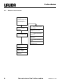
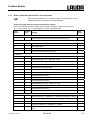
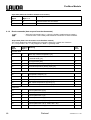
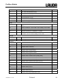
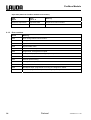
Operating instructions
Profibus Modules
Valid from series 1.36
02/06
YAAE0020
LAUDA DR. R. WOBSER
GMBH & CO. KG
P.O. Box 1251
97912 Lauda-Königshofen
Germany
Telephone: +49 9343/ 503-0
Fax: +49 9343/ 503-222
E-Mail [email protected]
Internet http://www.lauda.de
Profibus Module
Contents
1
SAFETY INFORMATION............................................................................................................................................4
2
INSTALLING THE MODULES..................................................................................................................................5
3
GENERAL INFORMATION........................................................................................................................................6
4
MENU STRUCTURE OF THE PROFIBUS MODULE.............................................................................................7
4.1
4.2
COMMAND MENU STRUCTURE ...................................................................................................................................7
MASTER MENU STRUCTURE .......................................................................................................................................8
5
ELECTRICAL CONNECTION....................................................................................................................................9
6
PROTOCOL .................................................................................................................................................................10
6.1
PROTOCOL "LARGE"................................................................................................................................................10
6.1.1
Write commands (data issued to the thermostat) ............................................................................................11
6.1.2
Read commands (data request from the thermostat) ......................................................................................12
6.1.3
Error numbers.................................................................................................................................................14
6.2
PROTOCOL "SHORT" ................................................................................................................................................15
7
PROFIBUS ERROR PROCESSING..........................................................................................................................16
8
ERROR CHECK LIST ................................................................................................................................................17
Explanation of signs:
Ì
YAAE0020 / 14.11.06
Danger:
This sign is used where there may be injury to
personnel if a recommendation is not followed
accurately or is disregarded.
Note:
Here special attention is drawn to some aspect. May
include reference to danger.
Reference
Refers to other information in different sections.
Contents
3
Profibus Module
1
Safety information
Follow the operating instructions for the thermostat!
Withdraw the mains plug before installing the modules.
Touch an earthed component or use an antistatic wrist band before unpacking the module.
4
− The Profibus module cannot be used in combination with an RS 232 / RS 485
module.
If necessary use the RS 232 / RS 485 interface on the command control panel.
Safety information
YAAE0020 / 14.11.06
Profibus Module
2
Installing the modules
The installation in a module slot is shown here using a Proline unit as an example. The same
procedure applies to other thermostats. In case of doubt refer to the operating manual for the
respective thermostat.
− Touch an earthed component, e.g. the bath cover
on the Proline thermostat or the bare interface
panel on the Integral XT, to discharge any
electrostatic charge. Or use an antistatic wrist
band before unpacking the module.
− Remove the module from its packaging.
− Switch off the thermostat and pull out the mains
plug.
− Insert a screwdriver into the lower recess of the
module cavity and pries up the plastic cover. The
cover can then be pulled off downwards.
− Pull out the plug of the bus connecting cable from
the plastic cover.
− Plug on the bus connecting cable (red plug onto
red socket).
− Insert the module and secure with the two crosshead screws.
− Connect the mains plug again and switch on the
thermostat.
YAAE0020 / 14.11.06
The plugs are protected against reverse polarity.
The plugs have a ridge which slides into a groove
in the socket.
Installing the modules
5
Profibus Module
3
General information
GSD file and ID no.
Name of the GSD file: LPBM0A2B.GSD
ID no.:
0x0A2B
The GSD file contains information for the master (e.g. the transmission baud rate, response times, ...)
and is provided together with the bitmap file.
Baud rate
The transmission rate used by the master is detected automatically by the Profibus module.
Transmission rates of up to 12 Mbaud are supported by the Profibus module.
Addressing
The Profibus address can be entered on the thermostat or assigned via the Profibus. As supplied, each
device is set with the default address of 126. This address is required when a new address is assigned
to the module via the Profibus. Before the system is put into operation, an address (from 1 to 125) which
has not yet been issued must be assigned to each newly added device.
Profibus error detection
The Profibus ASIC signals via the red LED when an error is present on the Profibus.
6
General information
YAAE0020 / 14.11.06
Profibus Module
4
Menu structure of the Profibus module
All existing menu points are illustrated. More extensive information can be found in the respective
operating manuals of the thermostats.
4.1
Command menu structure
Menu
Modules
Profibus
YAAE0020 / 14.11.06
Profibus address
Menu structure of the Profibus module
7
Profibus Module
4.2
Master menu structure
1%21
Actual bath temperature
or actual value of
external temperature
LMnet
Configure
modules
pR--- Configure serial
module
TDp : Display software version
of the module
T13 : Display 24V supply
voltage
Rlp^G : Module serial number
Places 1-5
Rlp^K : Module serial number
Places 6-10
B 777 : Protocol selected by
master
Dlc
Quit display level
@ 777 Select Profibus
address
RgmYW
Display level
cDE
Restore
default settings
Dlc
Quit menu
8
Menu structure of the Profibus module
YAAE0020 / 14.11.06
Profibus Module
5
Electrical connection
The data transmission occurs according to the RS485 standard.
− View of sockets on the plug side or of sockets on the solder side.
Contact
Name
Function
1
Reserved.
2
Reserved.
3
B
4
CNTR-P
5
GND
6
5V
7
8
9
Data line (+).
Control signal for repair.
Supply termination (-) and data reference potential.
Supply termination (+).
Reserved.
A
Data line (-).
Reserved.
The terminals 1, 2, 7 and 9 are reserved and must not be connected.
Use screened bus cables, the screens of which are earthed at both ends (e.g. plug case). The use of
Profibus standard cables is recommended.
YAAE0020 / 14.11.06
Electrical connection
9
Profibus Module
6
Protocol
The protocol is defined on the master with the project-definition tool via the module selection. Before
useful data can be interchanged on the Profibus, each slave is initialized by the master. To achieve this,
special telegrams with parameterization and configuration data are sent from the master to the slave.
Based on the configuration data, the Profibus module detects the chosen protocol.
6.1
Protocol "Large"
7 bytes are sent cyclically from the master to the Profibus module and 6 bytes are sent
from the Profibus module to the master.
Bytes from the master to the Profibus module.
Byte 1
Byte 2
Byte 3
Byte 4...7
Toggle Info
Command (Cmd)
Command no. (Cmd No) Value
Bytes from the Profibus module to the master
Byte 1
Byte 2
Byte 3...6
Toggle Info
Command (Cmd)
Value
An integrated toggle byte is used to detect whether an interrogation has been sent many times
consecutively or when the Profibus module has reacted to the command sent by the master. If the
master sends a new command, it must change the toggle byte. In its response the Profibus module
takes over the toggle byte sent by the master.
The command from the master is identified in the following tables by the command and the command
number. The reaction of the Profibus module is similarly identified via the command.
Some commands from the master and responses from the Profibus module include a numerical value.
This is always transmitted in a resolution of one thousandth.
10
Protocol
YAAE0020 / 14.11.06
Profibus Module
6.1.1
Write commands (data issued to the thermostat)
− With write commands bytes 4...7 always contain a numerical value. This is
always transmitted in a resolution of one thousandth.
Output data (data from the master to the Profibus module)
The column Relevance states whether the command is limited to a certain line of devices.
"P" => only Proline / "XT" => only Integral XT / blank => generally valid.
Cmd
Byte 2
Cmd No
Meaning
Byte 3
Relevance
Process value
1
0
External temperature to be set through the interface [°C].
2
0
Setpoint temperature [°C].
2
1
Pump output step.
2
4
TiH outflow temperature high limit [°C].
2
5
TiL outflow temperature low limit [°C].
3
0
Control parameter Xp [K].
3
1
Control parameter Tn (5...180s; 181 = Off).
3
2
Control parameter Tv [s].
3
3
Control parameter Td [s].
3
4
Control parameter KpE [Factor].
3
5
Control parameter TnE (0...998s; 999 = Off).
3
6
Control parameter TvE [s].
3
7
Control parameter TdE [s].
3
9
Max. outflow temperature limit [K].
3
10
Control parameter XpF [K].
3
11
Control parameter TnF (5...180s; 181 = Off).
3
12
Control parameter TvF [s].
3
13
Control parameter TdF [s].
3
14
Setpoint offset [K].
4
0
Keyboard master: 0 = released / 1 = locked (corresponds to: "KEY").
4
1
Control: 0=internal / 1=ext. Pt100 / 2=ext. analog / 3=ext. serial.
4
2
Standby operation: 0 = Unit on / 1 = Unit off.
4
3
Keyboard command: 0 = released / 1 = locked.
4
4
Setpoint offset source: 0=normal / 1=ext. Pt / 2=ext. analog / 3=ext.
serial.
Setpoint
Parameter
Modus
YAAE0020 / 14.11.06
Protocol
11
Profibus Module
Input data (data from Profibus module to the master)
6.1.2
Cmd
Byte 2
Value
Byte 3...6
Meaning
0
0
Communication was successful.
0xFF
Error number
Communication error.
Read commands (data request from the thermostat)
− With read commands bytes 3...6 from the Profibus module always contain a
numerical value. This is always transmitted in a resolution of one thousandth.
Output data (data from the master to the Profibus module)
The column Relevance states whether the command is limited to a certain line of devices.
"P" => only Proline / "XT" => only Integral XT / blank => generally valid.
Cmd
Byte 2
Cmd No
Meaning
Byte 3
Relevance
Process value
11
0
Bath resp. outflow temperature [°C].
11
1
Controlled temperature (internal / external Pt100 / external analog
/ external serial) [°C].
11
2
Pump pressure [bar].
11
3
External temperature (Pt100) [°C].
11
4
External temperature (analog input) [°C].
11
5
Level
12
0
Temperature setpoint [°C].
12
1
Pump output step.
12
3
Overtemperature switch-off point [°C].
12
4
TiH outflow temperature high limit [°C].
12
5
TiL outflow temperature low limit [°C].
13
0
Control parameter Xp [K].
13
1
Control parameter Tn (5...180s; 181 = Off).
13
2
Control parameter Tv [s].
13
3
Control parameter Td [s].
13
4
Control parameter KpE [Factor].
13
5
Control parameter TnE (0...998s; 999 = Off).
13
6
Control parameter TvE [s].
XT
Setpoint
Parameter
12
Protocol
YAAE0020 / 14.11.06
Profibus Module
13
7
Control parameter TdE [s].
13
9
Max. outflow temperature limit [K].
13
10
Control parameter XpF [K].
13
11
Control parameter TnF (5...180s; 181 = Off).
13
12
Control parameter TvF [s].
13
13
Control parameter TdF [s].
13
14
Set point offset [K].
14
0
Keyboard master: 0 = released / 1 = locked (corresponds to:
"KEY").
14
1
Control: 0=internal / 1=ext. Pt100 / 2=ext. analog / 3=ext. serial.
14
2
Standby operation: 0 = Unit on / 1 = Unit off.
14
3
Keyboard command: 0 = released / 1 = locked.
14
4
Setpoint offset source:
0=normal / 1=ext. Pt / 2=ext. analog / 3=ext. serial.
15
1
Device status: 0 = OK / 1 = Fault (error, alarm or warning).
15
2
Fault diagnosis.
16
0
Software version control system.
16
1
Software version protection system.
16
2
Software version command.
16
3
Software version cooling system.
16
4
Software version analog module.
16
5
Software version Profibus module.
16
6
Software version digital module.
16
7
Software version solenoid valve (cooling valve).
16
8
Software version solenoid valve (automatic refill valve).
16
9
Software version solenoid valve (constant level controller).
16
10
Software version solenoid valve (shut off unit 1).
16
11
Software version solenoid valve (shut off unit 2).
16
12
Software version pump 0.
16
13
Software version pump 1.
16
14
Software version pump 2.
16
15
Software version pump 3.
16
16
Software version high temperature cooler.
Mode
General
Versions
YAAE0020 / 14.11.06
Protocol
13
Profibus Module
Input data (data from Profibus module to the master)
6.1.3
14
Cmd
Byte 2
Value
Byte 3...6
Meaning
Cmd from output data
Requested data
Response to read command.
0xFF
Error number
Communication error.
Error numbers
Errors
Meaning
0x02
Error during internal communication.
0x03
Wrong command.
0x05
Syntax error in the value.
0x06
Impermissible value.
0x08
Module or value not present.
0x30
Programmer, all segments occupied.
0x31
No setpoint input possible, analog setpoint input ON.
0x32
TiH <= TiL.
0x33
External probe missing.
0x34
Analog value not present.
0x35
Automatic set.
0x36
No setpoint input, programmer is running or is stopped on Pause.
0x37
Start from programmer not possible, analog setpoint input is switched on.
Protocol
YAAE0020 / 14.11.06
Profibus Module
6.2
Protocol "Short"
− 32 bytes are interchanged cyclically between the master and the Profibus
module.
The significance of the individual bytes is described in the following tables.
Temperatures are always transmitted in the ASCII fixed point format "XXX.XX" or "-XX.XX".
Output data (data from the master to the Profibus module)
Byte
Meaning
Format
0...5
Setpoint temperature [°C]
"XXX.XX" or "-XX.XX" (ASCII).
Controller operation
'1' = Run / '0' = Standby (ASCII).
6
7...31
Free
Input data (data from Profibus module to the master)
Byte
Meaning
Format
0...5
Setpoint temperature [°C]
"XXX.XX" or "-XX.XX" (ASCII).
6...11
Internal temperature value (control system) [°C]
"XXX.XX" or "-XX.XX" (ASCII).
12...17
Actuating signal [%]
From "00-100" to "000100" (ASCII).
18...23
External temperature value from Pt100 [°C]
"XXX.XX" or "-XX.XX" (ASCII).
24...29
Internal temperature value (protection system)
[°C]
"XXX.XX" or "-XX.XX" (ASCII).
30
Operational status
'1' = Run / '0' = Standby (ASCII).
31
Status
0x00 = OK / 0xFF = Fault (Hex).
If the master specifies a new setpoint temperature via the output data, this only appears in the input
data when the new value has been accepted in the thermostat. The same applies to the start/stop byte.
YAAE0020 / 14.11.06
Protocol
15
Profibus Module
7
Profibus error processing
The red LED on the Profibus socket indicates a possible error Æ Profibus error.
The LED is directly driven from the Profibus ASIC and signals that the Profibus is not in the status
"DATA EXCHANGE".
If the Profibus module detects an error, the error number is transferred to the master via the Profibus as
an external diagnostic byte.
A differentiation is made between two error categories:
− Error 1...5 corresponds to a severe error. In this case the unit must be switched off and on again.
If the error still occurs, the Profibus module must be replaced and sent in for repair.
− Errors 6...15 are warnings. These are only displayed for one minute to provide information and
are then reset automatically.
16
Error number
Error description
0
Reserved.
1
Hardware error.
2
EEPROM error.
3
Internal memory error.
4
Fieldbus hardware error or wrong fieldbus ID.
5
Script error.
6
Reserved.
7
RS transmit buffer overflow
8
RS receive buffer overflow
9
RS timeout.
10
General fieldbus error.
11
Parity error.
12
Reserved.
13
Configuration error by the Profibus Master.
14
Fieldbus buffer overflow.
15
Reserved.
Profibus error processing
YAAE0020 / 14.11.06
Profibus Module
8
Error check list
The address set on the Profibus module does not match the address assigned in the master.
There are too many masters on the bus (e.g. parameterizing tools). The single master has too little time
available on the bus to control the system correctly.
There are large gaps between the allocated addresses. With large gaps the passing of the token
between two masters takes longer.
The bus cable has not been connected to the Profibus module.
The data lines A and B (or + and -) have been interchanged.
A bus cable is bad (high contact resistances) or it is defective. The use of Profibus standard cable is
recommended.
The bus cable is too long. The maximum length depends on the selected transfer rate.
The wrong cable was selected. Whereas cables of Type B are only suitable for transfer rates up to
1.5 Mbaud and only short bus lengths can be achieved, cables of Type A can be used up to 12 Mbaud
and longer maximum bus lengths can be achieved than for Type B with transfer rates up to and
including 1.5 Mbaud.
Too many devices are connected to the Profibus segment. With the RS485 transmission technology a
maximum of 32 devices can be connected.
The Profibus has not been terminated at both ends by active bus terminations.
The termination resistances on the active bus terminations have not been switched in. These must be
activated on the first and last devices on a Profibus segment.
The active bus terminations are not being supplied with voltage.
A bus termination in the middle of the Profibus segment is switched in.
The bust termination in a Profibus device is set incorrectly. Some devices already have a bus
termination integrated.
Too long spur lines have been used. Reflections, which can corrupt signals, arise due to spur lines.
Avoid using spur lines if possible.
No screened bus cable has been used.
The mesh screen and, where applicable, the foil screen located below it, have not been connected to
the protective earth (e.g. plug case) at both ends.
The transmission is briefly or permanently subject to EMC interference due to defective screening of the
bus cable.
Due to potential differences, a circulating current can flow between the earthing points via the screen
which is connected at both ends. In this case an additional potential equalization line between the
connected devices is recommended.
The bus cable has been routed in the vicinity of cables carrying heavy current.
A device with a different transmission technology has been connected to the Profibus segment (e.g.
current-modulated transmission technology according to IEC 61158-2, H1, Profibus PA).
YAAE0020 / 14.11.06
Error check list
17