1
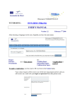
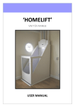
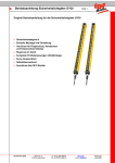
Operating instructions
Safety Relay
Original operating instructions for the safety relay for safety
light curtains
AO000299
Table of contents
ipf electronic gmbh
Important Notes
Page 2
Safety Regulations
Page 2
Designated Use
Page 3
Main Features
Page 3
Practical Notes
Page 3
Safety Notes
Page 4
Connection Terminals
Page 4
Function Diagram
Page 5
Block Diagram
Page 5
Indicators
Page 5
Setting
Page 5
Technical Data (input circuit / output)
Page 6
Technical Data (General Data)
Page 7
Safety related data
Page 7
Characteristics
Page 8
Dimensions
Page 8
Application examples
Page 9
Troubleshooting
Page 10
Maintenance and repairs
Page 10
Labeling and connections
Page 11
EC Declaration of Conformity
Page 12
Kalver Str. 27
D-58515 Lüdenscheid
fon +49 (0) 2351/9365-0
fax +49 (0) 2351/9365-19
www.ipf-electronic.com
[email protected]
Subject to alteration!
Version: July 2011
1
2
Operating instructions
Safety relay
Before installing, operating or maintaining this device, these instructions must be carefully read and understood.
Danger!
Dangerous voltage! Electric shock will result in death or serious injury.
Disconnect all power supplies before servicing equipment.
Caution!
Safe operation of the device is only guaranteed when using certified components.
Important Notes
The product hereby described was developed to perform safety functions as a part of a
whole installation or machine. A complete safety system normally includes sensors, evaluation units, signals and logical modules for safe disconnections The manufacturer of the
installation or machine is responsible for ensuring proper functioning of the whole system.
ipf cannot guarantee all the specifications of an installation or machine that was not designed by ipf. The total concept of the control system into which the device is integrated
must be validated by the user. ipf also takes over no liability for recommendations which
are given or implied in the following description The following description implies no modification of the general ipf terms of delivery, warranty or liability claims.
Safety Regulations
• This device must be installed and operated by staff who are familiar with these instructions and with the current regulations for safety at work and accident prevention.
• Pay attention to applicable local regulations, especially regarding safety measures.
• The shock protection on the connected elements and the cable insulation must be designed for the highest voltage applied to the device .
• Opening the device or implementing unauthorized changes voids any warranty.
• The unit should be panel mounted in an enclosure rated at IP 54 or superior. Dust and
dampness may lead to malfunction.
• Adequate fuse protection must be provided on all output contacts with capacitive and
inductive loads.
• The safety function must be triggered at least once a month.
ipf electronic gmbh
Kalver Str. 27
D-58515 Lüdenscheid
fon +49 (0) 2351/9365-0
fax +49 (0) 2351/9365-19
www.ipf-electronic.com
[email protected]
Subject to Alteration!
Version: July 2011
Operating instructions
Safety Relay
Designated use
The AO000299 is used for safe interruption of a safety circuit. It can be used to protect
people and machines in applications with light curtains.
When used in accordance with its intended purpose and following these operating instructions, this device presents no known residual risks. Nonobservance may lead to personal
injuries and damages to property.
Main featarues
• According to:
- Performance Level (PL) e and Category 4 to EN ISO 13849-1:2008
- SIL Claimed Level (SIL CL) 3 to IEC/EN 62061
- Safety Integrity Level (SIL) 3 to IEC/EN 61508
- Category 4 to EN 954-1
•
•
•
•
•
•
•
•
For light curtains with symmetric or asymmetric outputs, adjustment with switch S1
Output: 3 x no, 1 x nc (the nc-contact can only be used for monitoring)
Single and 2-channel operation
Line fault detection on On-button (monitored start)
Manual restart or automatic restart, switch S2
LED indicator for channel 1 and 2 and power
LED-Anzeigen für Kanal 1, 2 und Netz
Fixed screw terminals
Practical Notes
Line fault detection on On-button:
The line fault detection is only active when S12 and S22 are switched simultaneously. If
the ON-button is closed before S12, S22 is connected to voltage (also when line fault
across On-button), the ouput contacts will not close. A line fault across the On-button
which occurred after activation of the relay, will be detected with the next activation and the
output contacts will not close
The gold plated contacts of the AO000299 mean that this module is also suitable for
switching small loads of 1mVA … 7VA, 1mW … 7W in the range 0.1 … 60V, 1 … 300mA.
The contacts also permit the maximum switching current. However since the gold plating
will be burnt off at this current level, the device is no longer suitable for switchin small loads
after this.
The terminal S21 permits the operation of the device in IT-systems with insulation monitoring, serves as a reference point for testing the control voltage and is used to connect the Estop loop when cross fault monitoring is selected.
ipf electronic gmbh
Kalver Str. 27
D-58515 Lüdenscheid
fon +49 (0) 2351/9365-0
fax +49 (0) 2351/9365-19
www.ipf-electronic.com
[email protected]
Subject to alteration!
Version: July 2011
3
4
Operating instructions
Safety relay
To operate light curtains with symmetric outputs (both channels switching +) the selector
switch S1 has to be in position “without”. To operate light curtains with asymmetric ouputs
(1 channel switches +, one channel -) the selector switch S1 has to be in position “with”
The channel switching - must be connected to S22, channel switching + tom S12.
Safety Notes
ATTENTION! If a line fault occurs after the voltage has been connected to
S12, S22, the unit will be activated because this line fault is similar to the
normal On-function.
ATTENTION! Switch S1 must not be set while device is under supply voltage.
Switch S2 is used to select automatic or manual restart. Additionally, for the
function “automatic restart”, terminals S33 and S34 have to be bridged. Connect the device according to application examples. .
The ipf safety light curtains have a switching function between automatic and
manual start. If the function “manual start” is used at the safety light curtain, the
function “automatic restart” has to be chosen on the relay AO000299.
Connection Terminals
Terminal designation
Signal designation
A1 +
A2 S12, S22, S33, S34
S11, S21
13, 14, 23, 24, 33, 34
41, 42
Supply Voltage +
Supply Voltage Control Inputs
Control Ouputs
Forcibly guided NO contacts for release circuit
Forcibly guided NC contact (indicator output)
ipf electronic gmbh
Kalver Str. 27
D-58515 Lüdenscheid
fon +49 (0) 2351/9365-0
fax +49 (0) 2351/9365-19
www.ipf-electronic.com
[email protected]
Subject to Alteration!
Version: July 2011
Operating instructions
Safety Relay
Function Diagram
Block Diagram
Indicators
LED Power:
on when supply connected
LED K1/K2:
on when relay K1 and K2 energized
Setting
To set the switches S1 and S2 please remove the cover of the AO000299 in assistance of
a screwdriver etc. (see illustration).
The Drawing shows setting at the state of delivery.
Disconnect the unit before setting of S1!
ipf electronic gmbh
Kalver Str. 27
D-58515 Lüdenscheid
fon +49 (0) 2351/9365-0
fax +49 (0) 2351/9365-19
www.ipf-electronic.com
[email protected]
Subject to alteration!
Version: July 2011
5
6
Operating instructions
Safety relay
Technical Data
Input Circuit
Nominal Voltage UN
Voltage Range
Nominal consumption
Min. Off-time
Contro voltage on S11 at UN
Control current over S12, S22
Min. voltage on S12, S22
When relay activated
Short circuit protection
Overvoltage protection
24V DC
0,90 ... 1,1 UN
approx. 1,7W
250ms
22,5V DC
typ. 35mA at UN
21V DC
internal PTC
internal VDR
Output
3 NO-, 1 NC(The NC contacts 41-42 con only be used for monitoring)
Contacts
Operate delay (typ.) at UN
Manual start
Automatic start
Releas delay (typ.) at UN
Disconnecting the supply:
Disconnecting S12, S22
Nominal output voltage
Switching of low loads (contact 5µm Au)
Thermal Current Ith:
Switching capacity
to AC 15
to DC 13
20ms
15ms
max. 250V AC
DC: see limit curve for arc-free operation
≥ 100mV
≥ 1mA
max. 8A per contact (see current limit curve)
NO-contacts
NC-contacts
3A / 230V AC
2A / 230V AC
NO-contacts
4A / 24V DC
IEC/EN 60 947-5-1
0,5A / 110V DC IEC/EN 60 947-5-1
4A / 24V DC
IEC/EN 60 947-5-1
NC-contacts
to DC13
Schließer
Electrical contact life to 5A, 230V AC, cosφ = 1
Permissible operating frequency
Short circuit strength
max. fuse rating
line circuit breaker
ipf electronic gmbh
20ms
350ms
Kalver Str. 27
D-58515 Lüdenscheid
IEC/EN 60 947-5-1
IEC/EN 60 947-5-1
3
8A / 24V DC
> 25 x 10
5
> 1,5 x10 switching cycles
max. 1200 operating cycles / h
10A gL
B 6A
fon +49 (0) 2351/9365-0
fax +49 (0) 2351/9365-19
ON: 0,4s, OFF: 9,6s
IEC/EN 60 947-5-1
www.ipf-electronic.com
[email protected]
Subject to Alteration!
Version: July 2011
Operating instructions
Safety Relay
General Data
Operating mode
Temperature range
operation
storage
Altitude
Contact material
Clearance and creepage distances
Rated impulse Voltage
Pollution Degrie
EMC
Electrostatic discharge (ESD)
HF irradiation
Fast Transients
Surge Voltages
between wires for power supply
between wire and ground
Interference suppression
Degree of Protection
Housing
Terminals
Housing Material
Vibration resistance
Climate resistance
Terminal designation
Wire fixing
Mounting
Weight
Continuous operation
-15 … +55°C
-25 … +85°C
< 2000m
AgSnO2 or similar
4kV
2 (Basis insulation)
IEC 60 664-1
8kV (air)
10V/m
2kV
IEC/EN 61 000-4-2
IEC/EN 61 000-4-3
IEC/EN 61 000-4-4
0,5kV
2kV
Limit value class B
IEC/EN 61 000-4-5
IEC/EN 61 000-4-5
EN 55 011
IP40
IP20
Thermoplastic with V0-behaviour according to UL Subject 94
Amplitude 0,35mm, frequency 10 … 55Hz IEC/EN 60068-2-6
15 / 055 / 04
IEC/EN 60068-1
EN 50 005
Plus-Minus terminal screwsM3,5
Box terminals with wire protection
DIN rail
IEC/EN 60 715
220g
Safety related Data
EN ISO 13849-1
Category
PL
MTTFd
DCavg
dop
hop
tcycle
4
e
584,5a (year)
99,0%
220d/a (days/year)
12h/d (hours/day)
3600s/cycle (= 1/h)
IEC/EN 62061
IEC/EN 61508
SIL CL
SIL
HFT
DCavg
SFF
PFHD
3 (IEC/EN 62061)
3 (IEC/EN 61508)
1
99%
99,7%
-10 -1
2,66 x 10 h
ipf electronic gmbh
Kalver Str. 27
D-58515 Lüdenscheid
fon +49 (0) 2351/9365-0
fax +49 (0) 2351/9365-19
www.ipf-electronic.com
[email protected]
Subject to alteration!
Version: July 2011
7
8
Operating instructions
Safety relay
Characteristics
Arc limit curve under resistive load
Total current limit curve
Dimensions (in mm)
ipf electronic gmbh
Kalver Str. 27
D-58515 Lüdenscheid
fon +49 (0) 2351/9365-0
fax +49 (0) 2351/9365-19
www.ipf-electronic.com
[email protected]
Subject to Alteration!
Version: July 2011
Operating instructions
Safety Relay
Application examples
Single channel connection of light curtains with self-test
according to EN 61 496-1.
Note: Refer to “Setting”!
Switches in Position:
S1: “without”
S2: “manual”
2 channel connection of light curtains with self-test according to EN 61 496-1.
Cross fault detection in the light curtain.
Note: Refer to “Setting”!
Switches in Positions:
S1: With symmetric outputs on light curtains switch S1 in
position “without“.
With asymmetric outputs on light curtains switch S1 in
position “with“.
S2: “manual”
Contact reinforcement and contact extension by external
contactors.
Note: Refer to “Setting”!
Switches in Positions:
S1: With symmetric outputs on light curtains switch S1 in
position “without“.
With asymmetric outputs on light curtains switch S1 in
position “with“.
S2: “manual”S1:
ipf electronic gmbh
Kalver Str. 27
D-58515 Lüdenscheid
fon +49 (0) 2351/9365-0
fax +49 (0) 2351/9365-19
www.ipf-electronic.com
[email protected]
Subject to alteration!
Version: July 2011
9
10
Operating instructions
Safety relay
Troubleshooting
Failure:
Potential Course:
Action:
LED „Power“ does not
light up
LED „K1“ lights up,
but „K2“ remains off
- Power supply not connected
- Switch on the power supply!
- Safety relay K1 is welded
- A 1-channel switch-off occurred on S12
- Replace the device!
- Switch channel off on S22!
LED „K2“ lights up,
but „K1“ remains off
- Safety relay K2 is welded
- A 1-channel switch-off occurred on S22
- Replace the device!
- Switch channel off on S12!
Device cannot be activated
Manual Start Mode:
- Line fault on start-button
Automatic Start Mode:
- S33-S34 not bridged
- A safety relay is welded
- Incorrect setting of switch S1
- Disconnect power supply and
remove fault!
- Connect S33 with S34!
- Replace the device!
- Control switch S1 und bring it
in the correct position!
Maintenance and repairs
- The device contains no parts that require maintenance
- In case of failure, do not open the device but send it to the manufacturer for repair.
ipf electronic gmbh
Kalver Str. 27
D-58515 Lüdenscheid
fon +49 (0) 2351/9365-0
fax +49 (0) 2351/9365-19
www.ipf-electronic.com
[email protected]
Subject to Alteration!
Version: July 2011
Operating instructions
Safety Relay
Labeling and connections
ø 4 mm / PZ 1
0,8 Nm
7 LB. IN
A = 8mm
2
1 x 0,5 ... 4 mm
1 x AWG 20 to 12
2
2 x 0,5 ... 2,5 mm
2 x AWG 20 to 14
A = 8mm
2
1 x 0,5 ... 2,5 mm
1 x AWG 20 to 14
2
2 x 0,5 ... 1,5mm
2 x AWG 20 to 16
A = 8mm
2
1 x 0,5 ... 4mm
1 x AWG 20 to 12
2
2 x 0,5 ... 2,5mm
2 x AWG 20 to 14
ipf electronic gmbh
Kalver Str. 27
D-58515 Lüdenscheid
fon +49 (0) 2351/9365-0
fax +49 (0) 2351/9365-19
www.ipf-electronic.com
[email protected]
Subject to alteration!
Version: July 2011
11
12
Operating instructions
Safety relay
EC-Declaration of Conformity
The
ipf electronic gmbh
Kalver Str. 27
D – 58515 Lüdenscheid
declares hereby that the following product:
product description: safety switching device for electro-sensitive protective devices
type designation:
AO000299
conforms to the following European Standards:
EMC-Directive:
2004/108/EG
Machinery directive:
2006/42/EG
Basis of testing:
EN ISO 13849-1:2008 + AC
EN 62061
EN 60947-5-1:2004 + A1
EN 60204-1:2006 + A1
EN ISO 13850
EN 50178
:2009
:2005
:2009
:2009 (in extracts)
:2008
:1997
The product has been validated by the following testing institutes:
TÜV Rheinland Industrie Service GmbH
Alboinstraße 56
D - 12103 Berlin
Name of the documentation representative: Jörg Hesse
Adress of the documentation representative: see adress of the manufacturer
Lüdenscheid, 12.07.2011
signature J. Hesse
quality management representative
This declaration confirms the conformity of the mentioned directives but does not comprise any guarantee of the product characteristics.
The safety directives of the product documentation are to be considered.
ipf electronic gmbh
Kalver Str. 27
D-58515 Lüdenscheid
fon +49 (0) 2351/9365-0
fax +49 (0) 2351/9365-19
www.ipf-electronic.com
[email protected]
Subject to Alteration!
Version: July 2011