1
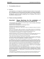
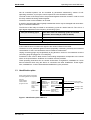
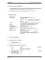
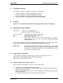
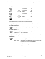
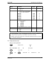
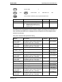
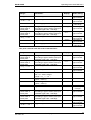
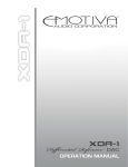
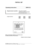
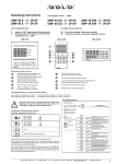
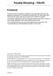
Operating Instructions
DMP 96 C
Multi-channel controller
Program version:
Two-point controller
11535
1
2
°C
3
4
5
°C
6
7
Scan
1
2
3
Static
∗
P
Tune
Start
5
6
Stop
4
Read and observe these operating instructions before commissioning the unit
(particularly the notes on installation, assembly and commissioning instructions).
Subject to technical and functional change
Dold GmbH, D70736 Fellbach, Blumenstr.33, Phone +49(0)711 95152-0, [email protected], www.dold-regler.de
DOLD GmbH
Operating Instructions DMP 96 C
Index:
1. The installation of the unit: .................................................................................. 3
1.1 General: ........................................................................................................................................3
1.2 Please note during installation: .....................................................................................................3
1.3 Identification plate: ........................................................................................................................4
1.4 Terminal connection diagram:.......................................................................................................5
1.5 Mechanical data: ...........................................................................................................................5
2. Inputs, technical data: .......................................................................................... 5
2.1 Inputs channel 1 to channel 4: ......................................................................................................5
2.2 Possible inputs channel 1 to channel 4: .......................................................................................5
2.3 Logic inputs ...................................................................................................................................6
2.4 Technical data of the inputs: .........................................................................................................6
2.4.1 Error-handling at inputs:.............................................................................................................6
3. Controller character:............................................................................................. 7
4. Outputs: ................................................................................................................. 7
4.1 Potential-free relay contacts: ........................................................................................................7
4.2 Logic outputs (optional):................................................................................................................7
4.3 Output responses in cases of error:..............................................................................................7
4.4 Optional analogue outputs (only valid for optional plug in PCB "C"): ...........................................8
5. Auxiliary power: .................................................................................................... 8
6. Display: .................................................................................................................. 8
6.1 Upper 7-segment display: .............................................................................................................8
6.2 Lower 7-segment display: .............................................................................................................9
6.3 LED's:............................................................................................................................................9
7. Operation: .............................................................................................................. 9
7.1 The Different levels: ....................................................................................................................11
7.2 Operation level: ...........................................................................................................................12
7.3 Extended Operation level:...........................................................................................................13
7.3.1 Unlocking the limit contacts: ....................................................................................................14
7.4 Configuration level: .....................................................................................................................14
7.5 Parametrication level: .................................................................................................................17
7.6 Self-tuning: ..................................................................................................................................21
7.6.1 Monitoring the optimization process: .......................................................................................22
8. Line Balancing, Zero Point Correction:............................................................. 23
9. Error and Faults: ................................................................................................. 23
9.1 List of possible error messages (display): ..................................................................................23
10. Program version: .............................................................................................. 23
11. Immunity: ........................................................................................................... 25
Supplement A: The serial interface (RS 485)
(only for units with serial interface RS-485).
Version: 115
35E115B 07.doc
Date: 08/2007
No. of pages: 25
2
DOLD GmbH
1.
Operating Instructions DMP 96 C
The installation of the unit:
1.1 General:
The unit DMP 96 C is a microprocessor controlled multi channel controller. The unit is obtainable in different devices. It contains 2 to 4 channels and between 0 and 8 freely configurable relays. The regulation function is configurable for each channel. In the following the maximum
equipment with 4 channels and 8 freely configurable relays is described. At slighter equipment
the parameters, which do not refer to available parts, are not adjustable. The unit may be
served only by competent personnel.
1.2 Please note during installation:
Important:
These directions for the installation of
DOLD devices have to be adhered to:
If these directions are not adhered to the device may not work accurately, be destroyed
or it may result in data being lost.
Read all directions carefully before connecting the device.
Connection to be carried out only by experts.
This device is not a safety device. Safety devices have to be installed according to the relevant
directions for use.
Check if the power-supply voltage corresponds to rated voltage indicated on the identification
plate before connecting and putting the device into operation. Fluctuations in the main voltage
are only admissible within the indicated limits (specifications/identification plate).
The described device is designated for the installation of switchboards.
Electrical connections are to be carried out according to the connecting plan and the directions
of the local electric supply company or the relevant regulations of the VDE respectively.
Other consumers must not be connected to the mains terminals.
In the event of mains interruptions, which lead to a malfunctioning of the device, relevant measures must be taken to avoid interruptions or interruptions must be filtered out by an external
hum eliminator. The device is equipped with an internal hum eliminator.
On installation the sensor lines have to be shielded. The screen must be single-ended. With regard to thermocouple pick-ups the compensating lead has to be laid as far as the control terminals. The device and inductive consumers as well as sensor lines/signal lines and high tension
lines have to be placed in such a way that any mutual interference is excluded (placed separately; not parallely laid). go-and-return lines should be laid parallely and, if possible, twisted.
Non-insulated sensors of a multi-channel control have to be adjusted to the same potential
(max. potential difference: ±3.5 V eff.). Otherwise insulated sensors must be used (Warning:
Ceramics insulations (Al-Oxide) can be conducting ≥400 °C).
Post-connected contactors have to be equipped with RC protective allocations according to the
manufacturer's instructions. If an internal protective allocation is mentioned in the connection
plan of the device this has to be taken into account in the event of external allocation. If external
allocation is missing short-term voltage peaks may result which lead to faster contact wear and
may cause interference.
The preadjustment of all parameters has to be checked during operation and adjusted to the local conditions (installation)! Wrongly adjusted parameters may cause serious malfunctions!
Version: 115
35E115B 07.doc
Date: 08/2007
No. of pages: 25
3
DOLD GmbH
Operating Instructions DMP 96 C
Not all controlled systems can be controlled by parameters measured by means of selfoptimising; therefore, on principle, control response is to be checked for stability.
The load circuits of the relays have to be protected against excessive currents in order to avoid
the relay contacts becoming welded together.
The device must not be installed in an ex-area.
If used for purposes other than originally intended the device may be damaged and cause damage to connected installations.
The life time of the relays is limited to 106 switching cycles at a load of 500 VA. Thus it is to a
high degree dependent on the frequency of switching cycles.
Time per switching cycle
Time after which 106 switching cycles are reached
(operation: 8 hours/day at a load of 500 VA)
2 minutes
about 11.4 years
60 s
about 5.7 years
30 s
about 2.8 years
This table is invalid for Solid-State-Relay.
At low loads life time increases with regard to the values indicated in the table.
The device is to be protected against moisture (especially condensing moisture) and excessive
contamination. If this is not assured the device is liable to malfunctions.
Unplug connecting plugs only longitudinally to plug direction. Under no circumstances must the
connecting plugs be plugged in or out obliquely!
Furthermore care must be taken that the surrounding temperature corresponds to the values
shown in the specifications. Sufficient air circulation must be provided.
These operating instructions do not contain all directions to regulations, standards etc. which
become effective when using this device in connection with other installations. These regulations, standards etc. must be ascertained and abided to by the purchaser.
1.3 Identification plate:
When making technical enquiries
the following details are important
unit type
works number
model number
program version
unit type
operating volts:
switching volts:
works number:
inputs:
outputs:
model number
ASP 675 XXX
XXX V +/-10%
500 VA bei 230 V AC
XXXXXX PXXFXXHXX
XXXXX
Relaisausgänge
Logikausgänge
Ausf. Nr.: 850XXX Programmversion: XXXXX
DMP 96 C
Betriebsspannung
Schaltleistung:
Fabriknummer:
Eingänge:
Ausgänge:
Terminal connection diagram number
according to order
500 VA at 230 V AC
according to order
relay outputs
logic outputs
according to order
program version
Figure 1: Identification plate DMP 96 C
Version: 115
35E115B 07.doc
Date: 08/2007
No. of pages: 25
4
DOLD GmbH
Operating Instructions DMP 96 C
1.4 Terminal connection diagram:
The connection diagram shows maximum terminal assignment for the controller when all connection possibilities are used. The appropriate terminal assignment (depending of the type of
controller used) can be found in the accompanying connection diagram.
Connection diagram number according to identification plate:
ASP 675XXX
1.5 Mechanical data:
Protection class:
Isolation group:
Type of protection:
Housing:
Material:
extinguishing,
Front panel dimensions:
Control panel cutout:
Recess depth:
Terminal connections:
Weight:
Ambient conditions:
2.
II
C as per DIN VDE 0110 b
As per DIN VDE 0470 (replaces DIN 40 050)
EN 60 529 / IEC 529
Front panel:
IP 50 (optionally: IP 54 with the proper
mounting and a suitable sealing ring)
Housing:
IP 30
Connections: IP 20
Pull-out housing for mounting control panel as per DIN 43 700
with a B fastener as per DIN 43 835 (M 4 screw clamp)
PPO, glass-fiber reinforced (Noryl GFN2SE1), selfnon-dripping, fire protection class UL 94 V1
96 x 96 mm DIN 43 700
92+0.8 x 92+0.8 mm
approx. 148 mm including screwed plug
Screwed socket strips, nominal cross section 2.5 mm2
approx. 420 g
Operating temperature range:
0...+50°C
Storage temperature range:
-30...+70°C
Climatic utilization category:
as per DIN 40 040,
corresponding to 75% relative humidity without moisture
condensation
Inputs, technical data:
2.1 Inputs channel 1 to channel 4:
•
•
according to order
according to identification plate.
2.2 Possible inputs channel 1 to channel 4:
•
•
Pt 100:
Pt 100:
Pt 100:
•
•
•
•
•
thermocouple Fe-CuNi:
thermocouple Ni-CrNi:
standard signal voltage
standard signal current
mix of different inputs is possible
Version: 115
35E115B 07.doc
Range:
Range:
input 1 and 2 in three wire lead,
input 3 and 4 in two wire lead
Range:
Range:
Date: 08/2007
No. of pages: 25
-100...600°C
-200...100°C
0...800°C
0...1200°C
5
DOLD GmbH
•
Operating Instructions DMP 96 C
other inputs on demand
2.3 Logic inputs
Logic inputs controlled with external, potential-free contacts, contact voltage approx. 5 V DC
Logic input 5: no function
Logic input 6: no function
Logic input 7: Start / Stop - function, controlled by level or by slope (configurable)
2.4 Technical data of the inputs:
Pt 100:
Pt 100 three-wire lead:
Pt 100 two-wire lead:
Sensor current:
constant 1 mA DC
Calibration precision:
≤ 0,15 % F.S.
Linearity error:
≤ 0,1% F.S.
Temperature drift characteristics:
≤ 100 ppm/K
Equipped with sensor breakage cutoff and short circuit fuse
Automatic line resistance compensation via software
(maximum permissible line resistance: 50 Ω per lead)
Line resistance correction (line compensation) of maximum 11 Ω
possible via software
Calibration precision:
≤ 0.15% F.S.
Linearity error:
≤ 0.15% F.S.
Temperature drift characteristics
(without reference point compensation):
≤ 80 ppm/K
Effect of line resistance:
≤ 2μV/Ω
Reference point compensation
Error recognition using a controller reference point > 70°C
Sensor breakage cutoff
thermocouple:
standard signal:
Calibration precision:
Linearity error:
Temperature drift characteristics:
standard signal current: input impedance:
standard signal voltage: input impedance:
General:
≤ 0.15% F.S.
≤ 0,1% F.S.
≤ 100 ppm/K
Ri = 100 Ω
Ri ≥ 10 kΩ
Measurement cycle:
1s
Resolution:
≥ 14 bit
RC and diode protection circuit for each input
Measuring-circuit monitoring: Error shown on display
Protective circuits:
Hardware watchdog and power-fail
Data backup:
EPROM, semiconductor storage,
Hardware-protected calibrated values.
2.4.1 Error-handling at inputs:
If the input signal is leaving the measurement range around more than approx. 10% (according
to chapters 2.2), it will be recognized as an error and indicated in the display. The regulation of
the corresponding entrance is stopped and the outputs, which are associated to this entrance,
according to the configuration activates or deactivates.
Version: 115
35E115B 07.doc
Date: 08/2007
No. of pages: 25
6
DOLD GmbH
3.
Operating Instructions DMP 96 C
Controller character:
The controller character of channel 1 to channel 4 is configurable:
•
•
•
•
4.
two point controller for heating with adjustable hysteresis
two point controller for cooling with adjustable hysteresis
two point controller for heating with PID controller characteristics
two point controller for cooling with PID controller characteristics
Outputs:
Outputs as per identification plate and accompanying terminal connection diagram:
4.1 Potential-free relay contacts:
Contact load:
≤ 250 V AC, ≤ 8 A resistive load
at 500 VA typically 106 switching cycles
K 1 to K 4, K 6, K 8:
K 5, K 7:
K 9:
configurable relay outputs, make contact
configurable relay outputs, change over
relay output, change over,
alarm contact, active in case of a sensor fault channel 1 to channel 4
(fault-messages 10, 11, 12, 13) or in case a hardware fault (faultmessages 30, 31, 32)
The amount of available relays can be ordered between 1 and 8 relays. The controller functions
and limit values functions are freely distributable to the available amount relays.
Please note:
Alarm contact K 9 and relay contacts (limit contacts K 1 to K 8), which
are inserted as alarm contacts, offer no protection against all possibilities of errors. If necessary the employment recommends itself a further,
independent checking equipment.
4.2 Logic outputs (optional):
Logic outputs for activating solid-state relays, (in place of relay outputs K 1 to K 4):
Open collector, not galvanically separated, short-circuit-proof,
typically: 0/10 V DC, maximum: 20 mA.
4.3 Output responses in cases of error:
Output response of the outputs K 1 to K 8 in cases of sensor error:
•
•
•
•
the regulation of the faulty channel will be stopped
outputs, which are associated to the faulty channel takes off the defined status to the configuration (configuration level)
approx. 20 s after removal of the error, the error message is picked up and the relay function is released again
the channels and relays who are not affected works continue duly.
Version: 115
35E115B 07.doc
Date: 08/2007
No. of pages: 25
7
DOLD GmbH
Operating Instructions DMP 96 C
4.4 Optional analogue outputs (only valid for optional plug in PCB "C"):
Voltage or current output according to purchase order (ranges according to configuration):
Output 1:
Output 2:
Output 3:
5.
actual value output of range of channel 1
actual value output of range of channel 2
actual value output of range of channel 3
Auxiliary power:
Auxiliary power (operating voltage) as per identification plate:
Standard:
Power consumption, depending on model:
Not affected by voltage fluctuations within the defined range.
6.
230 V AC (±10%), 48...62 Hz,
≤ 15 VA,
Display:
6.1 Upper 7-segment display:
shows according to status of controller:
6.1.1
after pushing the according operating key:
1
Channel number 1 and actual value channel 1
2
Channel number 2 and actual value channel 2
3
Channel number 3 and actual value channel 3
∗
4
Channel number 4 and actual value channel 4
6.1.2.
Scan - mode:
switching automatically from channel to channel showing
actual values and channel number one after another
6.1.3.
Static - mode:
after pushing two channel number keys at the same time,
the first actual value with its channel number is on display
6.1.4.
Parameter symbols in input mode.
Version: 115
35E115B 07.doc
Date: 08/2007
No. of pages: 25
8
DOLD GmbH
Operating Instructions DMP 96 C
6.2 Lower 7-segment display:
shows according to status of controller:
6.2.1.
after pushing the according operating key:
1
set point value channel 1 (without channel number)
2
set point value channel 2 (without channel number)
3
set point value channel 3 (without channel number)
∗
set point value channel 4 (without channel number)
4
6.2.2.
Scan - mode:
set point display (without channel number)
6.2.3.
Static - mode:
after pushing two channel number keys at the same time, the
second actual value with its channel number is on display
6.2.4.
Parameter symbols in input mode (4 digits).
6.3 LED's:
LED 1
LED 2
LED 3
LED 4
LED 5
LED 6
LED 7
LED 8
LED 9
7.
yellow
yellow
yellow
yellow
yellow
yellow
yellow
red
red
lights up when output K 1 is active
lights up when output K 2 is active
lights up when output K 3 is active
lights up when output K 4 is active
lights up when output K 5 is active
lights up when output K 6 is active
lights up when output K 7 is active
Scan / Static lights up in Scan - mode
Start / Stop lights up when controller has been started.
Operation:
The program structure of the DMP 96 C controller has four clearly defined levels:
•
•
•
•
the Operation level to alter set point values
the Extended Operation level to alter limit contact outputs (optional)
the Parametrication level to adapt the control parameters to the regulation requirements
and set point value ranges
the Configuration level to set up the line balance, the controller character, the error allocations, the interface (optional) and the limit contacts (optional).
Version: 115
35E115B 07.doc
Date: 08/2007
No. of pages: 25
9
DOLD GmbH
Operating Instructions DMP 96 C
Setting parameters on the various levels:
1
and
1
2
3
and
3
2
P
current value:
+1
current value:
after 3 s:
+10
+100
current value:
-1
current value:
after 3 s:
-10
-100
the value on display is entered.
5
After confirming the last parameter, return to normal operating mode.
If no key is pressed within 10 seconds, automatic return to normal operating mode, without accepting the changed parameters.
To activate the regulation:
Start
Stop
this key will enable or disable the regulation, providing the Start/Stop key is not
disabled in the configuration level.
To activate self-tuning 1):
Tune
6
To start or stop the self-tune operation in the respective channel set for with
parameter "t.ch" 1) see 7.6. self-tuning.
Start up the self-tuning is only possible, if to the discontinued channel also at least one relay is
configured as controller output on this channel.
Display mode:
Scan
Static
Scan - mode:
automatic display switch from one channel to the other for
actual and set point values of all channels.
Static - mode:
After pressing a channel select key the according actual channel and set point value will appear on display.
After pressing the same time two of the according channel select keys the according actual values are switched into the
displays.
Version: 115
35E115B 07.doc
Date: 08/2007
No. of pages: 25
10
DOLD GmbH
Operating Instructions DMP 96 C
7.1 The Different levels:
P
press for short time
P
5
Operation level
5
to push for about 3 s
P
5
Code
100
1
1
and
2
3
3
and
2
Code
72
Extended Operation level
Code
155
Configuration level
Code
55
Parametrication level
Code
109
Unlocking of the limit contacts
Figure 2: The various levels
Version: 115
35E115B 07.doc
Date: 08/2007
No. of pages: 25
11
DOLD GmbH
Operating Instructions DMP 96 C
7.2 Operation level:
Set point adjustments:
P
5
press for short time and jump to operation level
Range:
Parameter:
Display:
Works setting:
" 1.rdo "..." 1.ruP "
Common set point
for channel 1 to channel 4
(if configuration "4.SPt" = 0)
" SP.1 "
0.0°C
" 1.rdo "..." 1.ruP "
" 2.rdo "..." 2.ruP "
" 3.rdo "..." 3.ruP "
" 4.rdo "..." 4.ruP "
Set point channel 1
Set point channel 2
Set point channel 3
Set point channel 4
" SP.1 "
" SP.2 "
" SP.3 "
" SP.4 "
0.0°C
0.0°C
0.0°C
0.0°C
0...4
Self-tuning for channel 1 to channel 4
0: no self-tuning possible for channel 1
to channel 4
(Channel adjustment only possible if
parameter "no.t" = 0,
see parametrication level)
" t.ch "
0
(parameter only can be activated if
regulation output is set for PID control characteristic)
Version: 115
35E115B 07.doc
Date: 08/2007
No. of pages: 25
12
DOLD GmbH
7.3
Operating Instructions DMP 96 C
Extended Operation level:
Adjustment of the set point values of the configurable limit contacts:
Set point values setting is only possible, when corresponding output is configured for limit contact.
P
display to show:
5
" Cod "
100
Key in code number: Code
72
with the keys
Range:
Parameter:
"rdo" ... "rup"
(in dependent of
the selected channel)
X: depending upon
configuration
Set point value or spreading of the
limit contact
0.5...50.0°C
Version: 115
35E115B 07.doc
Display:
" x.Li X "
x: 1-8
"Li
"
limit contact absolute make contact
"Li
"Li
"
"
"Li
"
"Li
"
"Li
"
"Li
"Li
"LI
"
"
"
limit contact absolute break contact
limit contact relative to minus make
contact
limit contact relative to minus break
contact
limit contact relative to plus make
contact
limit contact relative to plus break
contact
limiting comparator make contact
limiting comparator break contact
limit contact absolute make contact
with locking
limit
contact absolute break contact
"LI
"
with locking
limit contact relative to minus make
"LI
"
contact with locking
limit contact relative to minus break
"LI
"
contact with locking
limit contact relative to plus make
"LI
"
contact with locking
limit contact relative to plus break
"LI
"
contact with locking
limiting comparator make contact with
"LI
"
locking
limiting comparator break contact with
"LI
"
locking
" x.HYS "
hysteresis limit contact
x: 1 - 8
Date: 08/2007
No. of pages: 25
Works setting:
20.0°C
1.0 °C
13
DOLD GmbH
Operating Instructions DMP 96 C
7.3.1 Unlocking the limit contacts:
After setting the code number the configured limit contacts can be unlocked.
P
display to show:
5
" Cod "
100
Key in code number: Code
P
109
code number confirmed, enter to operation level
5
7.4 Configuration level:
P
display to show:
5
" Cod "
100
Key in code number: Code
current value
1
1
155
and
2
with the keys:
+1
current value
+10
after about 3 s
+100
after about 3 s
-100
or
current value
3
3
and
P
2
-1
current value
-10
code number confirmed, jump to configuration level
5
Range:
Parameter:
1...20
Low-pass filter,
cycle time always is 1 s
1: direct measurement
2: two measurements are averaged
20: 20 measurements are averaged
standard preadjustment is three,
three measurements are averaged, the
latest measure will be replaced
Number of active channel
2...maximum number of channel
-30.0...+30.0°C
-30.0...+30.0°C
Version: 115
35E115B 07.doc
Line balance channel 1, offset value
will be added to actual value
Line balance channel 2, offset value
will be added to actual value
Date: 08/2007
No. of pages: 25
Display:
Works setting:
" ti.Fi "
3
"CH.no"
" 1.Lin "
according to
order
0.0°C
" 2.Lin "
0.0°C
14
DOLD GmbH
Operating Instructions DMP 96 C
Range:
Parameter:
Display:
Works setting:
-30.0...+30.0°C
Line balance channel 3, offset value
will be added to actual value
Line balance channel 4, offset value
will be added to actual value
Standard signal channel 1,
parameter only appears in configuration of standard signal
0: 0...20 mA or 0...10 V DC
1: 4...20 mA or 2...10 V DC
Standard signal channel 2,
parameter only appears in configuration of standard signal
0: 0...20 mA or 0...10 V DC
1: 4...20 mA or 2...10 V DC
Standard signal channel 3,
parameter only appears in configuration of standard signal
0: 0...20 mA or 0...10 V DC
1: 4...20 mA or 2...10 V DC
Standard signal channel 4,
parameter only appears in configuration of standard signal
0: 0...20 mA or 0...10 V DC
1: 4...20 mA or 2...10 V DC
Set point channel 1 to channel 4
0: one common set point for
channel 1 to channel 4
1: separate set points for
channel 1 to channel 4
Configuration of controller type,
controller output: channel 1
channel 2
channel 3
channel 4
0: heating controller with PIDcharacter
1: cooling controller with PIDcharacter
2: cooling controller with hysteresis
setting
3: cooling controller with hysteresis
setting
Configuration relay 1 to relay 8
" 3.Lin "
0.0°C
" 4.Lin "
0.0°C
" 1.i_4 "
0
" 2.i_4 "
0
" 3.i_4 "
0
" 4.i_4 "
0
" 4.SPt "
1
" 1rtY "
" 2rtY "
" 3rtY "
" 4rtY "
according to
order
" rEL.1 " " rEL.8 "
5
-30.0...+30.0°C
0...1
0...1
0...1
0...1
0...1
0...3
0...28
0; 6-8; 13-16; 21-24
Version: 115
35E115B 07.doc
no function (output deactivated)
1: limit contact absolute, to close on
rising temperature
17: just as with locking
2: limit contact tracking to minus, to
close on rising temperature,
18: just as with locking
3: limit contact tracking to plus, to
close on rising temperature,
19: just as with locking
Date: 08/2007
No. of pages: 25
15
DOLD GmbH
Range:
Operating Instructions DMP 96 C
Parameter:
Display:
4:
1-4
0...2
0...1
0...1
0...2
Version: 115
35E115B 07.doc
limit comparator, closed in good
band,
20: just as with locking
5: the output takes over the controller function heating or cooling belonging to the configured channel
9: limit contact absolute, to open on
rising temperature,
25: just as with locking
10: limit contact tracking to minus, to
open on rising temperature,
26 just as with locking
11: limit contact tracking to plus, to
open on rising temperature,
27 just as with locking
12: limit comparator, open in good
band
28: just as with locking
Channel selection for the corresponding output, the output works
with the setting channel
1: channel 1
2: channel 2
3: channel 3
4: channel 4
Analogue output of actual value (optional)
channel 1
channel 2
channel 3
0: voltage 0...10 V DC
current 0...20 mA
1: voltage 0...5 V DC
current 0...10 mA
2: voltage 0...2 V DC
current
0...4 mA
3: voltage 2...10 V DC
current 4...20 mA
voltage / current according to order
Automatic start - function
0: no automatic start if controller is
switched on
1: controller automatically starts
when switched on
Start/stop - key - function
0: normal start/stop-function via key
1: no start/stop-function, controller
automatically starts if switched on
(independent of parameter "Auto")
Start/stop - function with
logic input 7
0: no function
1: controlled by level
2
controlled by slope
Works setting:
Date: 08/2007
No. of pages: 25
"r1.Ch" "r8.Ch"
" 1dAc "
" 2dAc "
" 3dAc "
" Auto "
0
" noSt "
0
" Et.St "
0
16
DOLD GmbH
Operating Instructions DMP 96 C
Range:
Parameter:
0...1
Display resolution
0: without 1/10
1: with 1/10
Fault/error definitions
0: output in case of fault disabled
1: output in case of fault active
output K 1
output K 2
output K 3
output K 4
output K 5
output K 6
output K 7
output K 8
Baud rate
0: interface disabled
3:
300 Baud
6:
600 Baud
12:
1200 Baud
24:
2400 Baud
48:
4800 Baud
96:
9600 Baud
all other settings will result in 300 baud
Device address
Parity
0: none
1: odd
2: even
0...1
0...96
1...32
0...2
Display:
Works setting:
"diSP"
depending
upon range
" r1.FE "
" r2.FE "
" r3.FE "
" r4.FE "
" r5.FE "
" r6.FE "
" r7.FE "
" r8.FE "
" bAUd "
0
0
0
0
0
0
0
0
0
" Adr "
" PAri "
1
0
In case of parameter " 4.SPt " is reconfigured (one common set point or 4 different set
points) the set point adjustments in the operation level have to be checked.
Optional: in case of limit contactors are reconfigured its adjustments have to be checked
in the extended operating level.
7.5 Parametrication level:
Setting of control parameters:
P
display to show:
5
" Cod "
100
Key in code number: Code
current value
1
1
55
and
2
with the keys:
+1
current value
+10
after about 3 s
+100
or
Version: 115
35E115B 07.doc
Date: 08/2007
No. of pages: 25
17
DOLD GmbH
Operating Instructions DMP 96 C
current value
3
3
and
P
2
-1
current value
-10
after about 3 s
-100
code number confirmed, jump to paramerication level
5
Range:
Parameter:
0...30°C
0...1
Tune difference from set point
Define self-tune channel
0: self-tuning for channel 1 to 4
1: disable the input of a self-tune
channel "t.ch"
Scan - time display
0...60 s
Display:
Works setting:
" t.di "
" no.t "
0.0°C
0
" Sc.t "
3
According to the configuration of the controller outputs (according to the purchase order) only those parameters are on display which correspond to the according function!
Function of controller:
Two point controller with hysteresis setting
Range:
Parameter:
according to purchase order or
name plate
according to purchase order or
name plate
" 1.rt_ "..." 1.rt─ "
Range start channel 1, range setting
according to type of sensor; with input
standard signal -200...1000 Digit
Range end channel 1, range setting
according to type of sensor; with input
standard signal -200...1000 Digit
Lower set point limit channel 1
" 1.rdo "..." 1.rt─ "
Upper set point limit channel 1
" 1.ruP "
0.2...10.0°C
Switching hysteresis channel 1
" 1-HY "
according to purchase order or
name plate
according to purchase order or
name plate
" 2.rt_ "..." 2.rt─ "
Range start channel 2, range setting
according to type of sensor; with input
standard signal -200...1000 Digit
Range end channel 2, range setting
according to type of sensor; with input
standard signal -200...1000 Digit
Lower set point limit channel 2
" 2.rt_ "
" 2.rt─ "
according to
type of sensor
" 2.rdo "
" 2.rdo "..." 2.rt─ "
Upper set point limit channel 2
" 2.ruP "
0.2...10.0°C
Switching hysteresis channel 2
" 2-HY "
according to purchase order or
name plate
according to purchase order or
name plate
Range start channel 3, range setting
according to type of sensor; with input
standard signal -200...1000 Digit
Range end channel 3, range setting
according to type of sensor; with input
standard signal -200...1000 Digit
" 3.rt_ "
according to
type of sensor
according to
type of sensor
0.5% of set
point range
according to
type of sensor
Version: 115
35E115B 07.doc
Date: 08/2007
No. of pages: 25
Display:
Works setting:
" 1.rt_ "
according to
type of sensor
" 1.rt─ "
according to
type of sensor
" 1.rdo "
according to
type of sensor
according to
type of sensor
0.5% of set
point range
according to
type of sensor
" 3.rt─ "
according to
type of sensor
18
DOLD GmbH
Operating Instructions DMP 96 C
Range:
Parameter:
Display:
Works setting:
" 3.rt_ "..." 3.rt─ "
Lower set point limit channel 3
" 3.rdo "
" 3.rdo "..." 3.rt─ "
Upper set point limit channel 3
" 3.ruP "
0.2...10.0°C
Switching hysteresis channel 3
" 3-HY "
according to purchase order or
name plate
according to purchase order or
name plate
" 4.rt_ "..." 4.rt─ "
Range start channel 4, range setting
according to type of sensor; with input
standard signal -200...1000 Digit
Range end channel 4, range setting
according to type of sensor; with input
standard signal -200...1000 Digit
Lower set point limit channel 4
" 4.rt_ "
according to
type of sensor
according to
type of sensor
0.5% of set
point range
according to
type of sensor
" 4.rt─ "
according to
type of sensor
" 4.rdo "
" 4.rdo "..." 4.rt─ "
Upper set point limit channel 4
" 4.ruP "
0.2...10.0°C
Switching hysteresis channel 4
" 4-HY "
according to
type of sensor
according to
type of sensor
0.5% of set
point range
Two point controller with PID control characteristics:
Range:
Parameter:
according to purchase order or
name plate
according to purchase order or
name plate
" 1.rt_ "..." 1.rt─ "
Range start channel 1, range setting
according to type of sensor; with input
standard signal -200...1000 Digit
Range end channel 1, range setting
according to type of sensor; with input
standard signal -200...1000 Digit
Lower set point limit channel 1
" 1.rdo "..." 1.rt─ "
Upper set point limit channel 1
" 1.ruP "
0.1...99.9%
Proportional band channel 1
Pb = 0.1...99.9% refer to
range " 1.rt_ "..." 1.rt─ "
0...499 s
0...100%
2...60 s
Time derivative channel 1
(set 0 = value 0)
Time integral channel 1
(set 0 = value 0)
Maximum integral channel 1
Cycle time channel 1
according to purchase order or
name plate
according to purchase order or
name plate
" 2.rt_ "..." 2.rt─ "
Range start channel 2, range setting
according to type of sensor; with input
standard signal -200...1000 Digit
Range end channel 2, range setting
according to type of sensor; with input
standard signal -200...1000 Digit
Lower set point limit channel 2
" 2.rt─ "
according to
type of sensor
" 2.rdo "
" 2.rdo "..." 2.rt─ "
Upper set point limit channel 2
" 2.ruP "
according to
type of sensor
according to
type of sensor
0...2000 s
Version: 115
35E115B 07.doc
Date: 08/2007
No. of pages: 25
Display:
Works setting:
" 1.rt_ "
according to
type of sensor
" 1.rt─ "
according to
type of sensor
" 1.rdo "
" 1-Pb"
according to
type of sensor
according to
type of sensor
10.0 %
" 1-td "
100 s
" 1-ti "
400 s
" 1-IE "
" 1 CY "
30 %
30 s relay
5 s logic
according to
type of sensor
" 2.rt_ "
19
DOLD GmbH
Operating Instructions DMP 96 C
Range:
Parameter:
Display:
Works setting:
0.1...99.9%
Proportional band channel 2
Pb = 0.1...99.9% refer to
range " 2.rt_ "..." 2.rt─ "
" 2-Pb "
10.0 %
0...499 s
" 2-td "
100 s
" 2-ti "
400 s
0...100%
2...60 s
Time derivative channel 2
(set 0 = value 0)
Time integral channel 2
(set 0 = value 0)
Maximum integral channel 2
Cycle time channel 2
" 2-IE "
" 2-CY "
according to purchase order or
name plate
according to purchase order or
name plate
" 3.rt_ "..." 3.rt─ "
Range start channel 3, range setting
according to type of sensor; with input
standard signal -200...1000 Digit
Range end channel 3, range setting
according to type of sensor; with input
standard signal -200...1000 Digit
Lower set point limit channe 3
30 %
30 s relay
5 s logic
according to
type of sensor
" 3.rt─ "
according to
type of sensor
" 3.rdo "
" 3.rdo "..." 3.rt─ "
Upper set point limit channel 3
" 3.ruP "
0.1...99.9%
Proportional band channel 3
Pb = 0.1...99.9% refer to
range " 3.rt_ "..." 3.rt─ "
" 3-Pb "
according to
type of sensor
according to
type of sensor
10.0 %
0...499 s
" 3-td "
100 s
" 3-ti "
400 s
0...100%
2...60 s
Time derivative channel 3
(set 0 = value 0)
Time integral channel 3
(set 0 = value 0)
Maximum integral channel 3
Cycle time channel 3
" 3-IE "
" 3-CY "
according to purchase order or
name plate
according to purchase order or
name plate
" 4.rt_ "..." 4.rt─ "
Range start channel 4, range setting
according to type of sensor; with input
standard signal -200...1000 Digit
Range end channel 4, range setting
according to type of sensor; with input
standard signal -200...1000 Digit
Lower set point limit channel 4
30 %
30 s relay
5 s logic
according to
type of sensor
" 4.rt─ "
according to
type of sensor
" 4.rdo "
" 4.rdo "..." 4.rt─ "
Upper set point limit channel 4
" 4.ruP "
0.1...99.9%
Proportional band channel 4
Pb = 0.1...99.9% refer to
range " 4.rt_ "..." 4.rt─ "
" 4-Pb"
according to
type of sensor
according to
type of sensor
10.0 %
0...499 s
Time derivative channel 4
(set 0 = value 0)
Time integral channel 4
(set 0 = value 0)
Maximum integral channel 4
Cycle time channel 4
" 4-td "
100 s
" 4-ti "
400 s
" 4-IE "
" 4-CY "
30 %
30 s relay
5 s logic
0...2000 s
0...2000 s
0...2000 s
0...100%
2...60 s
Version: 115
35E115B 07.doc
Date: 08/2007
No. of pages: 25
" 3.rt_ "
" 4.rt_ "
20
DOLD GmbH
Operating Instructions DMP 96 C
7.6 Self-tuning:
For matching the regulator to the regulator path, the DMP 96 C is provided with a tuning facility.
The tuning algorithm is based on modified Ziegler-Nichols rules, whereby the nominal data of
the path are determined following an oscillation test in a closed control loop.
These nominal data - in particular the oscillation cycle and amplitude - form the basis for calculating the relevant parameters.
Initiation self-tuning:
The tuning process can be activated at any time, if the controller has been started,
by pressing the key
Tune
6
(5 seconds).
Tuning is then effected on the channel selected by the parameter "t.ch".
The tune facility must be cleared at the parametrication level.
Tuning Example - heating
Controlled variable
Controlled variable
Tuning on start-up
Set point
Tuning following regulation
to set point
Set point
Tuning variation
Auxiliary set point
t
Auxiliary set point
t
Start of tuning
Start of tuning
Figure 3: Tuning example
In the tuning procedure, the algorithm employs an auxiliary set point value, which diverges from
the set point value by the amount preset in the parametrication level.
Auxiliary set point = set point - "t.di"
During the tuning procedure, the controller works with the P-regulating characteristic
(Pb = 0,1%), and as an optical check, the set point and the "OPt" are shown alternately on the
lower display.
In order to calculate the parameters, the controller requires two oscillations following which it
runs the control variable to the set point.
Once the tuning procedure is finished, only the current set point appears on the lower display.
The calculated parameters are saved to the EEPROM where they are protected against power
failure. They can now be called up at any time and altered manually.
Version: 115
35E115B 07.doc
Date: 08/2007
No. of pages: 25
21
DOLD GmbH
Operating Instructions DMP 96 C
Aborting tuning:
Tune
The tuning procedure can be aborted at any time by pressing
6
(5 seconds).
The regulator confirms the aborted status by dimming the lower display.
The key
Tune
6
must then be cleared to return the regulator to the normal mode.
7.6.1 Monitoring the optimization process:
The diagrams show possible incorrect settings with suggestions as to how to correct them.
X
X
(°C)
(°C)
(°C)
W
W
W
X
Pb too small
Control oscillating
Pb too large
slow start-up
and poor control
Optimum setting
t
t
t
X
X
(°C)
(°C)
(°C)
W
W
W
X
Ti too large
Optimum setting
Ti too small
t
t
t
X
X
(°C)
X
(°C)
(°C)
W
W
W
Td too large
Optimum setting
Td too small
t
t
t
Figure 4: Incorrect settings of the feedback parameters
Version: 115
35E115B 07.doc
Date: 08/2007
No. of pages: 25
22
DOLD GmbH
8.
Operating Instructions DMP 96 C
Line Balancing, Zero Point Correction:
Line balancing or zero point correction can be effected to the respective channel with the parameters " 1.Lin " to " 4.Lin " (channel 1 to channel 4).
When the actual value is calculated, the offset value set is either added to, or subtracted from it.
9.
Error and Faults:
9.1 List of possible error messages (display):
Errordisplayed:
Cause:
Action /Description:
1
2
3
Writing error I²C-bus
Attempted division by zero
Wrong low-pass filter entered
(parameter " ti.Fi ")
Switch unit off/on
Switch unit off/on
Re-enter parameter " ti.Fi"
and switch unit off/on
10
Check sensor
11
12
13
Sensor error channel 1 or
sensor error channel 1 to 4 during
self-tuning
Sensor error channel 2
Sensor error channel 3
Sensor error channel 4
Check sensor
Check sensor
Check sensor
30
31
32
Reading error E²prom
Device not calibrated
Calibration faulty
Switch unit off/on
Return unit for calibration
Return unit for calibration
10. Program version:
112
35
internal factory number
actual software number
actual software and program numbers:
•
Version 010
22.12.93
basic version: multi channel PID controller
•
Version 020
08.03.94
added:
limit contacts 1 to 5 (optional)
•
Version 021
09.05.94
added:
configuration according to purchase order:
heating or cooling PID controller, heating or
cooling controller with adjustable switching
hysteresis; for max. three analogue outputs.
Version: 115
35E115B 07.doc
Date: 08/2007
No. of pages: 25
23
DOLD GmbH
•
Operating Instructions DMP 96 C
Version 022
03.06.94
added:
correction:
separate set points for channel 1 to 4,
operation level changed.
09.06.94: name of parameters "X.rdo" and
"X.ruP" in the operation instructions.
•
Version 023
22.06.94
correction:
two point controller with hysteresis setting:
start up self-tuning disabled.
•
Version 024
05.08.94
new function:
error acknowledgement by code 110;
each relay can take off controller functions or
limit values functions. The channel who refers
the function, can be discontinued in the configuration level.
Units with 2 and 3 channels and free numbers
of relay are disposable;
units with analogue outputs current 4...20 mA
are deliverable.
•
Version 025
05.08.94
correction:
controlling of limit contacts 1 to 5.
•
Version 030
02.02.95
new function:
insert a new interface routine for visual software, revision of the software program.
•
Version 031
09.02.95
new function:
limit contacts with locking configurable.
•
Version 110
23.05.95
new function:
Pt 100: channel 1 and channel 2 always three
wire lead,
controller character channel 1 to channel 4
configurable,
error-handling of the outputs changed,
no total locking of the outputs in case of an input error.
•
Version 111
18.03.96
correction:
by switching on the unit in auto start - function
the relays don't attract shortly.
•
Version 112
22.09.97
new function:
start/stop - function by logic input 7,
set point value setting by pressing the key for
short time,
parameter for lower range and upper range
according to type of sensor,
range of standard signal value configurable
(0...20 mA / 4...20 mA or
0...10 V DC / 2...10 V DC).
•
Version 113
18.05.98
new function:
interface software expanded (parameter higher
0x3ff now describable via interface).
immunity added to operating manual.
•
Version 114
23.07.98
new function:
additional parameters now accessible via
interface,
releasing function of the integrator changed.
•
Version 115
23.09.98
correction:
evaluation of the logic inputs changed.
•
Version 115
21.08.07
change
Company-Logo and-Address
Version: 115
35E115B 07.doc
Date: 08/2007
No. of pages: 25
24
DOLD GmbH
Operating Instructions DMP 96 C
11. Immunity:
The noise immunity of the controller has been tested using noise immunity test equipment of
the Schaffner company (CH).
•
Type NSG 222A:
interference simulator with fast interference pulses, a wide band
interference spectrum, a very short rise time and little energy
testdata:
•
Type NSG 225A:
Type NSG 203A:
35E115B 07.doc
step 3:
frequency:
2000 V
5 kHz
test with mains line interruption
testdata:
Version: 115
± 2500 V
5 ns
burst simulator with a wide band interference spectrum and a very
short rise time
testdata:
•
puls polarity:
rise time:
symmetrical and asymmetrical coupling
Date: 08/2007
100% mains line interruption:
frequency:
No. of pages: 25
50 ms
1 Hz
25