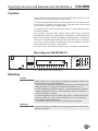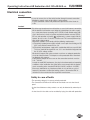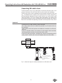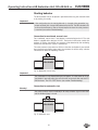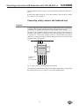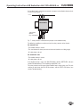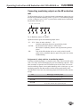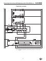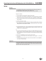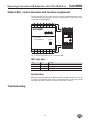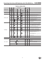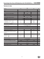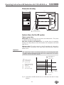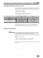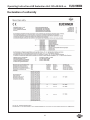
1
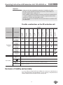
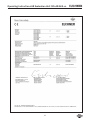
Operating Instructions
AR Evaluation Unit
CES-AR-AES-12
More than safety.
Operating Instructions AR Evaluation Unit CES-AR-AES-12
Contents
Correct use
Possible combinations on the AR evaluation unit
3
4
Exclusion of liability and warranty
4
General safety instructions
5
Function
Block diagram CES-AR-AES-12
6
6
Mounting
6
Electrical connection
Safety in case of faults
Connecting AR switch chain
Starting behavior
Connecting safety contacts and feedback loop
Connecting monitoring outputs on the AR evaluation unit
Connection example
7
7
9
10
11
13
14
Setup
15
Status LEDs, control elements and terminal assignment
LED indicators
Reset button
16
16
16
Troubleshooting
System status table
16
17
Technical data
Dimension drawing
System times for the AR system
18
19
19
Ordering information and accessories
20
Inspection and service
20
Service
21
Declaration of conformity
22
2
Operating Instructions AR Evaluation Unit CES-AR-AES-12
Correct use
The AR evaluation unit is used for the central evaluation of safety-related signals
in AR switch chains.
In combination with a separating safety guard and the machine control, this safety
component prevents dangerous machine movements from occurring while the
safety guard is open. A stop command is triggered if the safety guard is opened
during the dangerous machine function or if guard locking is deactivated.
Before safety switches are used, a risk assessment must be performed on the
machine in accordance with:
ÌÌEN ISO 13849-1, Safety of machinery. Safety related parts of control systems.
General principles for design
ÌÌEN ISO 12100, Safety of machinery – General principles for design – Risk assessment and risk reduction.
ÌÌIEC 62061, Safety of machinery. Functional safety of safety-related electrical,
electronic and programmable electronic control systems.
Correct use includes compliance with the relevant requirements for installation
and operation, in particular
ÌÌEN ISO 13849-1, Safety of machinery. Safety related parts of control systems.
General principles for design
ÌÌEN 1088, Safety of machinery. Interlocking devices associated with guards.
Principles for design and selection
ÌÌEN 60204-1, Safety of machinery. Electrical equipment of machines. General
requirements
ÌÌEN 60947-5-3 Specification for low-voltage switchgear and controlgear. Con-
trol circuit devices and switching elements. Requirements for proximity devices
with defined behavior under fault conditions
Only safety switches that are suitable for operation in an AR switch chain can be
evaluated. Check the operating instructions for the related safety switch. Combination with devices that are not suitable for use in an AR switch chain or with devices
from other manufacturers is not permitted. A maximum of 12 safety switches in
an AR switch chain can be connected to the AR evaluation unit CES-AR-AES-12.
Unicode and Multicode version switches can be connected. Unicode and Multicode
versions can be combined in an AR switch chain.
Important!
ÌÌThe user is responsible for the integration of the device into a safe overall
system. For this purpose, the overall system must be validated, e.g. in accordance with EN ISO 13849-2.
ÌÌCorrect use requires observing the permissible operating parameters (see
Technical data).
ÌÌIf a product data sheet is included with the product, the information on the
data sheet applies in case of discrepancies with the operating instructions.
ÌÌIn the estimation of the PL for the overall system, a maximum value of
100 years can be assumed for the MTTFd according to the limit value in
EN ISO 13849-1:2008, section 4.5.2. This corresponds to a minimum value
for the PFHd of 2.47x10⁻⁸/h.
ÌÌWhen up to 11 devices are connected in series, these limit values can be
assumed for the entire switch chain as a subsystem. As a subsystem, this
switch chain achieves PL e.
3
Operating Instructions AR Evaluation Unit CES-AR-AES-12
Important!
ÌÌIn the case of series connection of more than 11 switches in a chain,
the PFHd can be calculated according to one of the stated methods in
EN ISO 13849-1:2008, Section 4.5.1.
ÌÌIf the simplified method according to Section 6.3 of EN ISO 13849:2008-12
is used for validation, the Performance Level (PL) might be reduced when
more than 11 devices are connected in series.
ÌÌIt is only allowed to use components that are permissible in accordance with
the table below.
Possible combinations on the AR evaluation unit
CET-A-BWK-50X
096 327
104 730
CES-A-BDN-06-104730
103 450
CES-A-BLN-U2-103450
104 510
CES-A-BLN-L2-104510
100 776
100 251
CES-A-BRN
098 775
CES-A-BPA
088 786
CES-A-BCA
071 840
Safety switch
CES-A-BBA
Evaluation unit
CES-A-BLN-R2-100776
Actuator
CES-AR-C01...
from V1.1.2
(see rating plate on
the device)
CES-AR-CR2...
from V1.1.2
(see rating plate on
the device)
AR evaluation unit
CES-AR-AES-12
098 225
CES-AR-CL2...
from V1.1.2
(see rating plate on
the device)
CET1/2-AR...
from V1.1.2
(see rating plate on
the device)
CET3/4-AR...
from V1.0.0
(see rating plate on
the device)
/
Combination possible / combination on request
Combination possible, guard locking for process protection
Key to symbols
/
Combination possible, guard locking for personal protection / combination on request
Combination not permissible
Exclusion of liability and warranty
In case of failure to comply with the conditions for correct use stated above, or
if the safety instructions are not followed, or if any servicing is not performed as
required, liability will be excluded and the warranty void.
4
Operating Instructions AR Evaluation Unit CES-AR-AES-12
General safety instructions
Safety switches fulfill personal protection functions. Incorrect installation or tampering can lead to severe injuries to personnel.
The number of teach-in and switching operations is saved in the internal memory in
the AR evaluation unit. If necessary, this memory can be read by the manufacturer.
Check the safe function of the safety guard particularly
ÌÌafter any setup work
ÌÌafter the replacement of a CES component
ÌÌafter an extended period without use
ÌÌafter every fault
Independent of these checks, the safe function of the safety guard should be
checked at suitable intervals as part of the maintenance schedule.
Warning!
Danger of fatal injury in the event of incorrect connection or incorrect use.
ÌÌSafety switches must not be bypassed (bridging of contacts), turned away,
removed or otherwise rendered ineffective.
On this topic pay attention in particular to the measures for reducing the possibility of bypassing from EN 1088:1995+A2:2008, Section 5.7.
The device is only allowed to be installed and placed in operation by authorized
personnel
ÌÌwho are familiar with the correct handling of safety components ÌÌwho are familiar with the applicable EMC regulations
ÌÌwho are familiar with the applicable regulations on health and safety and accident prevention ÌÌwho have read and understood the operating instructions.
Important!
Prior to use, read the operating instructions of the CES component used and
keep them in a safe place. Ensure the operating instructions are always available
during mounting, setup and servicing. EUCHNER cannot provide any warranty
in relation to the readability of the CD/DVD for the storage period required. For
this reason you should archive a printed copy of the operating instructions. You
can download the operating instructions from www.EUCHNER.de.
5
Operating Instructions AR Evaluation Unit CES-AR-AES-12
Function
The AR evaluation unit is used to evaluate the individual safety switches in an AR
switch chain and to reliably interrupt a safety circuit.
The unit has two inputs for the connection of an AR switch chain. The safety contacts
are switched as a function of the input signals. Downstream parts of the safety
circuit can be monitored using a feedback loop.
The switching states of the connected safety switches can be signaled by means
of monitoring outputs.
If the actuator on one of the safety switches in the AR switch chain is moved out
of the operating distance or if guard locking is deactivated, the AR evaluation unit
opens its relay contacts and the corresponding monitoring output is switched off.
The system is designed so that failures will not result in the loss of the safety function. The occurrence of failures is detected by cyclic self-monitoring at the latest
at the next demand to close the safety contacts.
The system can be started either manually using a start button or automatically.
Block diagram CES-AR-AES-12
UB
UB
X6:4 X5:4
IA
IB
X8:1
X8:2
Y1
Y2
S
X5:1 X5:2 X5:3
switch chain
13
23
33
43
14
24
34
44
Feedback
Loop
Mon itoring Outputs
DC 24 V
098225
X6:3
0V
CES- AR
X6:2
DIA
X8:3
UB AR
X8:4
0V AR
X3:1 X3:2 X3:3 X3:4 X7:1 X7:2 X7:3 X7:4 X4:1 X4:2 X4:3 X4:4
O1
O2
O3
O4
O5
O6
O7
O8
O9
O10 O11 O12
X6:1
OUT AR
Fig. 1: Block diagram AR evaluation unit
Mounting
Caution!
Safety switches must not be bypassed (bridging of contacts), turned away,
removed or otherwise rendered ineffective.
ÌÌOn this topic pay attention in particular to the measures for reducing the possibility of bypassing according to EN 1088:1995.A2:2008, sec. 5.7.
ÌÌThe AR evaluation unit must be mounted in a control cabinet with a minimum
degree of protection of IP 54. A snap-in element on the rear of the device is
used for fastening to a DIN rail.
ÌÌIf several evaluation units are mounted side by side in a control cabinet without air circulation (e.g. fan), a minimum distance of 10 mm must be maintained between the evaluation units.
This distance enables the heat from the evaluation unit to dissipate.
Important!
Follow the mounting instructions in the accompanying documents for the safety
switches connected.
6
Operating Instructions AR Evaluation Unit CES-AR-AES-12
Electrical connection
Warning!
In case of an error, loss of the safety function through incorrect connection.
ÌÌMonitoring outputs must not be used as safety outputs.
ÌÌLay the connection cables with protection to prevent the risk of short circuits.
Caution!
Risk of damage to equipment or malfunctions as a result of incorrect connection.
ÌÌAll the electrical connections must either be isolated from the mains supply
by a safety transformer according to IEC 61558-2-6 with limited output voltage in the event of a fault, or by other equivalent isolation measures (PELV).
ÌÌFor use and operation as per the
requirements, a power supply with the
feature "for use in class 2 circuits" must be used. The same requirement applies to the safety outputs.
Alternative solutions must comply with the following requirements:
a)Electrically isolated power supply unit with a max. open-circuit voltage of 30
V/DC and a limited current of max. 8 A.
b)Electrically isolated power supply unit in combination with fuse as per UL248.
This fuse should be designed for max. 3.3 A and should be integrated into
the 30 V/DC voltage section.
ÌÌAll electrical outputs and safety contacts must have an adequate protective
circuit for inductive loads. The outputs must be protected with a free-wheeling diode for this purpose.
ÌÌThe tightening torque for the screws on the connection terminals must be
0.6 ... 0.8 Nm.
ÌÌIn order to avoid EMC interference, the physical environmental and operating
conditions at the installation site of the device must comply with the requirements according to the standard EN 60204-1:2006, section 4.4.2 (EMC).
ÌÌPlease pay attention to any interference fields in case of devices such as
frequency converters or induction heating systems. Observe the EMC instructions in the manuals from the respective manufacturer.
Safety in case of faults
ÌÌThe operating voltage UB is reverse polarity protected.
ÌÌThe connections UB AR and 0V AR for the read heads are not short circuitproof.
ÌÌA short circuit between safety contacts can only be detected by external pulsing.
ÌÌA short circuit in the cable can be excluded by laying the cable with protection.
7
Operating Instructions AR Evaluation Unit CES-AR-AES-12
Power supply
The power supply of 24 V DC is supplied to the AR evaluation unit. The AR switch
chain must be supplied with DC 24 V DC by the AR evaluation unit.
+24 V
0V
0V +UB +UB
connected together
internally
CES-AR-AES
PE must be connected
Fig. 2: Power to
supply
A2 for the ground
PE
fault detection
8
Operating Instructions AR Evaluation Unit CES-AR-AES-12
Connecting AR switch chain
The AR evaluation unit has two safety inputs to which the AR switch chain is connected. Safety inputs IA and IB have short circuit and earth fault monitoring.
The AR switch chain must be supplied by the AR evaluation unit (terminals UBAR and
0VAR). An additional power supply may be required for these safety switches (e.g.
for guard locking), depending on which safety switches are used in the AR switch
chain (see Figure 5). In case of switches with guard locking, the supply for the
guard locking solenoid must be at the potential of the AR evaluation unit. Information on this is provided in the operating instructions of the respective safety switch.
Important!
A maximum of 12 safety switches can be connected.
Only safety switches that are suitable for operation in an AR switch chain can
be connected.
Safety switches with start input are not suitable for connection to an AR evaluation unit.
In the case Unicode switches, the actuators must be taught-in at the read head.
See the operating instructions for the related safety switch.
For the AR system to function, a bridging plug must be connected to the first
safety switch in the AR switch chain (or a jumper between IA, IB and UBAR).
CES-AR-AES
IA IB
UB
AR
0V
AR
Connection for
guard locking
solenoid
CES-AR-C01 # n-1
Use common ground potential
for AR evaluation unit and operation of the solenoid!
See Connection example on
page 14.
STATE
DIA
CET-AR # n
CES-AR-C.2 # 1
Fig. 3: Schematic diagram showing connection of an AR switch chain
9
Operating Instructions AR Evaluation Unit CES-AR-AES-12
Starting behavior
The AR evaluation unit can be placed in operation either using the autostart mode
or by starting it manually.
Important!
If the configuration for the starting behavior is changed during operation (e.g.
jumper removed), this change will be detected by the unit. The AR evaluation unit
assumes the fault state as soon as the next request to close the safety contacts
is received (see section Troubleshooting).
Connection for monitored, manual start
For a monitored, manual start, a start button is connected to terminal S. The start
button is supplied with a voltage of 24 V DC. The terminal +UB can be used for this
purpose. A sticking start button, for example, will be detected by the monitoring
function the next time the system is powered up.
The safety contacts close after max. 600 ms when the start button is pressed and
then released again (falling edge) and if the actuators for all the safety switches
connected are within the operating distance.
S
UB
CES-AR-AES
Fig. 4: Monitored, manual start
Important!
The start button is only allowed to be pressed approx. 8 s after power on. If the
start button is pressed earlier, the unit will switch to the fault state and the LED
DIA illuminates. The LED STATE flashes (see section Troubleshooting).
Connection for automatic start
Warning!
The safety contacts close immediately if all safety switches signal a safe state
and the feedback loop is closed.
S
Y1
CES-AR-AES
Fig. 5: Automatic start
10
Operating Instructions AR Evaluation Unit CES-AR-AES-12
For the autostart mode, a jumper must be connected between the terminals S
and Y1.
By pulsing the output signal on Y1 the device detects short circuits on starting
(e.g. static DC 24 V on input S).

Connecting safety contacts and feedback loop
Important!
If you do not connect the feedback loop, the downstream devices will not be
monitored. This situation will affect the safety category of your system.
The unit has four redundant, positively driven safety contacts that switch off immediately if the actuator is removed at one of the connected safety switches or
if a fault occurs. To check the switching state of a connected load, the auxiliary
contacts on a contactor or relay can be connected to terminals Y1 and Y2 to form
a feedback loop (see Figure 6).
+24 V
13 23 33 43
CES-AR-AES
14 24 34 44 Y1 Y2
Subsequent
devices
(e.g. contactors)
Fig. 6: Safety contacts and feedback loop connected
The unit detects external short circuits on the feedback loop at the start by pulsing
the output signal on Y1 (e.g. static DC 24 V on the feedback loop).
11
Operating Instructions AR Evaluation Unit CES-AR-AES-12
If a feedback loop is not to be connected, a jumper must be fitted to the terminals
Y1 and Y2 (see Figure 7). +24 V
13 23 33 43
CES-AR-AES
14 24 34 44 Y1 Y2
Subsequent
devices
(e.g. contactors)
Fig. 7: Safety contacts connected and jumper on the feedback loop
The following conditions must be met for the safety contacts to be closed:
For manual start
ÌÌThe feedback loop is closed
ÌÌThe start button has been pressed and released (switches on falling edge)
ÌÌAll safety doors closed
For automatic start
ÌÌThe feedback loop is closed
ÌÌAll safety doors closed
If the feedback loop is open, the DIA LED flashes and the STATE LED is lit (see
section Troubleshooting). The monitoring output DIA is set.
The safety contacts remain open if the feedback loop is open at the start. The unit
switches to fault state, the DIA LED illuminates, and the STATE LED flashes (see
section Troubleshooting).
12
Operating Instructions AR Evaluation Unit CES-AR-AES-12
Connecting monitoring outputs on the AR evaluation
unit
The AR evaluation unit has 14 short-circuit-proof semiconductor outputs that can
be used to signal different operating states, e.g. to a PLC. If the monitoring output
is active, a voltage of max. 24 V DC is present at the related terminal (referred to
the potential at terminal 0 V).
min. 0,8x UB ; max. 20 mA
O1
O2
O3
O12
OUT
AR
DIA
Fig. 8: Monitoring outputs CES-AR-AES
Significance of the signals with monitoring output active:
ÌÌO1 ... O12:Status of safety switches 1 ... 12
(actuator at operating distance or guard locking status)
ÌÌOUT AR:All connected safety switches in state Enable.
(All actuators in operating distance and all guard locking devices
active)
ÌÌDIA:Fault on the AR evaluation unit or on a safety switch in the AR
switch chain, or feedback loop was open during start (see section
Troubleshooting)
Assignment of safety switches to monitoring outputs
At least one monitoring output is assigned to each safety switch in the AR switch
chain. The safety switch with bridging plug has the monitoring output O1. From
here, the output assignments are incremented up to the last switch in the chain.
Several monitoring outputs are occupied depending on the switch type, e.g. one
monitoring output for the door position and one for the guard locking status.
The table below shows how many monitoring outputs the individual safety switches
occupy.
Series
Number (type) of monitoring outputs
CES-AR
1
(door position, OUT or diagnostics DIA)
CET1/2-AR
1
(status of guard locking OUT)
CET3/4-AR
2
(door position OUT D and status of guard locking OUT)
13
Operating Instructions AR Evaluation Unit CES-AR-AES-12
Connection example
24V
0V
UB
-U1
RST
IA
8
IB
6
Read Head
2
1
Safety Output
7
5
CES
0V
UB
-U2
3
OUT
RST
OB
IA
8
IB
6
Read Head
2
4
OA
1
Safety Output
7
5
CES
0V
3
OUT
4
OA
OB
- S18
13
14
-B1
CET
UCM
X2:4
J
LED1
UB
X2:5 X2:3
RST
X1:2
IA
X1:8
X1:6
Actuator
Read Head
24 V DC Door
Mon itoring
Mon itoring Output
RD
X2:1
X1:7
0V(UCM)
UB
-K1
UB
X6:4 X5:4
0V
IA
IB
X8:1
X8:2
X2:2
X1:1
Safety
Output
X1:5
OUTD
IB
Safety
Inputs
Safety
Output
X1:3
OUT
X1:4
OA
OB
Y1
Y2
S
X5:1 X5:2 X5:3
switch chain
13
23
33
43
14
24
34
44
Feedback
Loop
Mon itoring Outputs
DC 24 V
098225
X6:3
0V
24V
CES- AR
X6:2
DIA
X8:3
X8:4
UB AR
0V AR
X3:1 X3:2 X3:3 X3:4 X7:1 X7:2 X7:3 X7:4 X4:1 X4:2 X4:3 X4:4
O1
O2
O3
O4
O5
O6
O7
O8
O9
O10 O11 O12
X6:1
OUT AR
0V
Fig. 9: Connection example for a mixed switch chain with 2 x CES-AR and 1 x
CET-AR
14
Operating Instructions AR Evaluation Unit CES-AR-AES-12
Setup
Warning!
ÌÌPay attention to the notes on commissioning and on the teach-in process in
the operating instructions for the safety switch used.
ÌÌIn case of devices with teach-in input, ensure the circuit is correct.
Proceed as follows:
1. Ensure nobody can be placed in danger during setup.
2. Prior to setup, check whether all connections are correct (jumpers connected,
external circuit correct) and the AR switch chain is fitted with a bridging plug.
3. Close all safety guards and make sure that the feedback loop on the evaluation
unit is closed.
4. Switch on the power supply.
¨¨ The switches in the chain are initialized on starting. Unicode switches that have
not yet taught-in an actuator on starting, automatically teach-in the actuator.
This process can take up to one minute.
¨¨ If the AR evaluation unit is set up for automatic start, the OUT LED flashes and
signals that the self-test is being performed. After the self-test, the OUT and
STATE LEDs are continuously lit.
or
¨¨ If you start the AR evaluation unit manually, the STATE LED flashes and signals
that the self-test is being carried out. After the self-test, the STATE LED illuminates continuously. The OUT LED flashes, since no start command has been
issued yet.
5. Press the start button (only necessary for manual start).
6. Then press the RST button on the AR evaluation unit for approx. 3 s to re-start
the device.
7. Check the correct function of the safety circuits connected. In case of problems,
see section Troubleshooting.
Important!
Use the status table in the section Troubleshooting to check the overall function.
In addition, the status LEDs on the respective safety switches provide information
about the status of the respective switch.
15
Operating Instructions AR Evaluation Unit CES-AR-AES-12
Status LEDs, control elements and terminal assignment
The AR evaluation unit has status LEDs for the most important operating states.
The significance of the individual LED states is explained in the System Status table
in the section Troubleshooting.
13
23
33
43
OUT
AR
14
24
34
44
Y1
DIA 0V +UB
Y2
S
+UB
EUCHNER
DIA OUT STATE
13
23
33
43
OUT
AR
14
24
34
44
Y1
DIA 0V +UB
Y2
S
+UB
EUCHNER
Safety Unit
DIA OUT STATE
Safety Unit
CES-AR
RESET
CES-AR-AES-12
RESET
O4
O5
O6
O7
O8
O9 O10 O11 O12
IA
IB
UB
AR
0V
AR
O1
O2 O3
O2 O3
O4
O5
O6
O7
O8
O9 O10 O11 O12
IA
IB
UB
AR
0V
AR
O1
Fig. 1: Terminal assignment, LEDs and reset button
LED indicators
LED
Color
Significance
STATE
green
Device status
OUT
yellow
Switch chain status
DIA
red
Fault display
Reset button
With the reset button pressed, the power supply for the AR evaluation unit and as
a result for the entire AR switch chain is interrupted. After it is released, the AR
evaluation unit and the switches connected restart with a self-test.
Troubleshooting
16
Operating Instructions AR Evaluation Unit CES-AR-AES-12
System status table
Door monitoring outputs
Fault display
OUT (yellow)
open
DIA (red)
off
off
off
Self-test after power up
off
off
off
Normal operation, at least one door open
closed
On
On
off
Normal operation, all doors closed
closed
off
On
off
Normal operation, all doors closed, start button not
pressed or fault in the feedback loop
closed
off
On
On
Normal operation, all doors closed, feedback loop
was open during attempt to start
X
X
7x
off
On
Faulty data transmission for status signals (safety
circuit not affected)
X
off
1x
off
On
Fault in the AR switch chain (e.g. fault on starting the
switch chain or more than 12 devices connected)
STATE
(green)
DIA
Normal operation
X
State
OUT AR
Self-test
Safety outputs
OA and OB
Operating mode
Actuator/
guard position
Indicator LEDs
15 Hz
(8 s)
3 Hz
4x
X
X
off
2x
off
On
Fault on the safety outputs or on the start button
(e.g. start configuration changed in operation, no/
erroneous signals from the switch chain, broken
cable on one of the channels IA or IB, or short circuit/
ground fault on one of the cables IA or IB)
X
off
4x
off
On
Fault on the safety relay, re-start device.
If fault is still indicated, contact manufacturer.
X
off
5x
off
On
Internal component fault, re-start device.
If fault is still indicated, contact manufacturer.
- Fault in feedback loop, e.g.
- feedback loop not connected on power up
- missing jumper between Y1/Y2
X
off
X
off
6x
off
On
off
On
or
- Fault in the start button, e.g.
- on autostart: jumper between S/UB instead of S/
Y1
- Start button stuck
Start failed three times, contact manufacturer
LED not illuminated
LED illuminated
Key to symbols
15 Hz (8 s)
LED flashes for 8 seconds at 15 Hz
3x
LED flashes three times
X
Any state
17
Operating Instructions AR Evaluation Unit CES-AR-AES-12
Technical data
Value
Parameter
min.
typ.
Housing material
max.
Unit
Plastic PA6.6
Dimensions
114 x 99 x 22.5
Weight
mm
0.25
kg
Ambient temperature at UB = DC 24 V
-20
-
+55
°C
Atmospheric humidity, not condensing
-
-
80
%
Degree of protection according to EN 60529
IP20
Degree of contamination
2
Mounting
DIN rail 35 mm according to EN 60715
Connection (plug-in screw terminals/coded)
0.14
-
Operating voltage UB (regulated, residual ripple < 5 %)
2.5
24 ± 10%
mm²
V DC
Current consumption IB (with relay energized) 1)
-
1.2 1)
-
A
External fuse (operating voltage UB)
-
2.5
8
A gG
Safety contacts
4 (relays with internally monitored contacts)
Switching current (relay outputs)
- at switching voltage
AC/DC 21 ... 60 V
1
-
300
- at switching voltage
AC/DC 5 ... 30 V
10
-
6000
- at switching voltage
AC
10
-
5000
5 ... 230 V
External fuse (safety circuit) according to EN 60269-1
mA
6 A gG or 6 A circuit breaker (characteristic B or C)
Utilization category acc. to EN 60947-5-1
AC-12 60V 0.3A / DC-12 60V 0.3A
AC-12 30V 6A / DC-12 30V 6A
AC-15 230V 5A / DC-13 24V 5A
Rated insulation voltage Ui
Rated impulse withstand voltage Uimp
Resilience to vibration
250
V
4
kV
In acc. with EN 60947-5-2
Mechanical operating cycles (relays)
10 x 106
Current via feedback loop Y1/Y2
5
8
10
mA
Permissible resistance via feedback loop
-
-
600
W
Monitoring outputs (O1 ... O12, DIA and OUT AR,
semiconductor outputs, p-switching, short-circuit-proof)
- Output voltage
0.8 x UB
-
UB
V DC
- Max. load
-
-
20
mA
- Switching frequency
-
1
-
Hz
Start button input S, test input TST
- Input voltage
LOW
0
-
2
HIGH
15
-
UB
- Input current
HIGH
5
8
10
Safety inputs IA, IB
V DC
mA
2 (for CES-AR switch chain)
Number of connectible safety switches
Max. 12
EMC protection requirements
In acc. with EN 60947-5-3
Reliability values according to EN ISO 13849-1
as a function of the switching current at 24 V DC
≤ 0.1 A
Category
≤3A
4
Performance Level (PL)
e
PFHd
Mission time
Number of switching cycles/year
≤1A
1.5 x 10⁻⁸
720 000
1) Taking into account the load currents at the monitoring outputs (20 mA each)
18
20
540 000
years
107 000
Operating Instructions AR Evaluation Unit CES-AR-AES-12
Dimension drawing
45
13
23
33
43
OUT
AR
14
24
34
44
Y1
114
DIA 0V +UB
Y2
S
+UB
EUCHNER
Safety Unit
DIA OUT STATE
99
CES-AR
RESET
O2 O3
O4
O5
O6
O7
O8
O9 O10 O11 O12
IA
IB
UB
AR
0V
AR
O1
Suitable for DIN rail
according to DIN 60715
System times for the AR system
Typical system times
Ready delay: After switching on, the unit carries out a self-test for 8 s. The system
is ready for operation only after this time.
Risk time according to EN 60947-5-3: If an actuator leaves the operating
distance, the safety contacts on the AR evaluation unit are opened at the latest
after 520 ms.
Difference time: The safety contacts on the AR evaluation unit switch with a
slight time offset. They have the same signal state at the latest after a difference
time of 10 ms.
Important!
The system times shown are maximum values for a circuit arrangement with
12 safety switches connected in an AR switch chain. Shorter times can also be
achieved in circuits with fewer switches.
Fault detection
Normal
operation
= Safety outputs active
toff = Switch-off time
t0 = Fault time/event
Actuator removal
or deactivating of
a guard locking
Non-identical input state
on IA/IB or short circuit
on IA or IB
or internal fault
Short circuit on IA/IB
t (ms)
toff = t0 + 750 ms
t0
toff = t0 + 520 ms
toff = t0 + 450 ms
Fig. 9: System times for AR evaluation unit on an AR switch chain with 12 safety
switches
19
Operating Instructions AR Evaluation Unit CES-AR-AES-12
Ordering information and accessories
Check whether all parts are complete. The connection terminals are not included
with the unit. Cables for connection of the AR switch chain must also be ordered
separately. Refer to the operating instructions of the safety switches used.
The following parts are supplied:
ÌÌ1 AR evaluation unit CES-AR-AES-12
ÌÌSafety information and maintenance (please retain!)
ÌÌCD with operating instructions (please retain!)
Series
Category and PL according to EN ISO 13849‑1
/
Version
Order No.
AR evaluation unit
CES-AR-AES-12
4 / PL e
098225
CES-AR-AES-12
Plug-in screw terminals
104776
CES-EA-TC-AK08-104776
Plug-in spring terminals
112629
CES-EA-TC-KK08-112629
Connection set
for AR evaluation unit CES-AR-AES-12
For ordering information on connection components, please refer to the accompanying documents, safety switches used or current sales documentation.
You can obtain additional installation material or spare parts from EUCHNER.
Inspection and service
Danger!
Loss of safety function due to damage to unit or the connected safety switches.
In case of damage the related component must be replaced.
Regular inspection of the following is necessary to ensure trouble-free long-term
operation:
ÌÌCheck the switching function
ÌÌCheck the secure fastening of the devices and the connections
ÌÌCheck for soiling (e.g. the ventilation slots on the housing)
No servicing is required, repairs to the device are only allowed to be made by the
manufacturer.
20
Operating Instructions AR Evaluation Unit CES-AR-AES-12
Service
If service support is required, please contact:
EUCHNER GmbH + Co. KG
Kohlhammerstraße 16
D-70771 Leinfelden-Echterdingen
Service telephone:
+49 711 7597-500
E-mail:
[email protected]
Internet:
www.euchner.de
21
Operating Instructions AR Evaluation Unit CES-AR-AES-12
Declaration of conformity
22
Operating Instructions AR Evaluation Unit CES-AR-AES-12
23
Euchner GmbH + Co. KG
Kohlhammerstraße 16
D-70771 Leinfelden-Echterdingen
[email protected]
www.euchner.de
Edition:
098221-03-01/13
Title:
Operating Instructions AR Evaluation Unit CES-AR-AES-12
(translation of the original operating instructions)
Copyright:
© EUCHNER GmbH + Co. KG, 01/2013
Subject to technical modifications,
no responsibility is accepted for the accuracy
of this information.
More than safety.