1
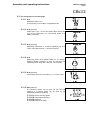
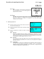
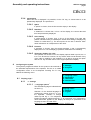
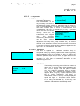
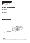
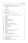
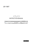
Assembly and operating instructions
AKOvisc 410-001
Assembly and operating instructions
AKOvisc
Viscosity measurement and control plant
erst. 23.08.1996
Assembly and operating instructions
AKOvisc 410-001
1 General . . . . . . . . . . . . . . . . . . . . . . . . . . . . . . . . . . . . . . . . . . . . . . . . . . . . . . . . . . . . . . . . . . . . page1 . . . . . . . . . . . . . . . . .
2 Assembly . . . . . . . . . . . . . . . . . . . . . . . . . . . . . . . . . . . . . . . . . . . . . . . . . . . . . . . . . . . . . . . . . . page2 . . . . . . . . . . . . . . . . .
2.1 Assembly position . . . . . . . . . . . . . . . . . . . . . . . . . . . . . . . . . . . . . . . . . . . . . . . . . . . . . page2 . . . . . . . . . . . . . . . . .
2.2 Pipework . . . . . . . . . . . . . . . . . . . . . . . . . . . . . . . . . . . . . . . . . . . . . . . . . . . . . . . . . . . . . . . page2 . . . . . . . . . . . . . . . . .
2.3 Mating flanges . . . . . . . . . . . . . . . . . . . . . . . . . . . . . . . . . . . . . . . . . . . . . . . . . . . . . . . . . page2 . . . . . . . . . . . . . . . . .
2.4 Measuring probe motor connectionr. . . . . . . . . . . . . . . . . . . . . . . . . . . . . . . . . . . page2 . . . . . . . . . . . . . . . . .
2.5 Temperature measurement with PT 100 resistance thermometer . . . . . . page2 . . . . . . . . . . . . . . . . .
2.6 Electrical connection of control valve . . . . . . . . . . . . . . . . . . . . . . . . . . . . . . . . . page3 . . . . . . . . . . . . . . . . .
2.7 Start/Stop control device . . . . . . . . . . . . . . . . . . . . . . . . . . . . . . . . . . . . . . . . . . . . . . page3 . . . . . . . . . . . . . . . . .
2.8 Plus and minus alarm . . . . . . . . . . . . . . . . . . . . . . . . . . . . . . . . . . . . . . . . . . . . . . . . . . page3 . . . . . . . . . . . . . . . . .
2.9 Electronic processing unit mains connection . . . . . . . . . . . . . . . . . . . . . . . . . page3 . . . . . . . . . . . . . . . . .
2.10 Output A 02 and A 03 (optional) 4 - 20 mA . . . . . . . . . . . . . . . . . . . . . . . . . . . . page3 . . . . . . . . . . . . . . . . .
2.11 Pin assignment of counter-plugs . . . . . . . . . . . . . . . . . . . . . . . . . . . . . . . . . . . . . page4 . . . . . . . . . . . . . . . . .
3 Switching the plant on . . . . . . . . . . . . . . . . . . . . . . . . . . . . . . . . . . . . . . . . . . . . . . . . . . . . . page5 . . . . . . . . . . . . . . . . .
4 Configuring the system . . . . . . . . . . . . . . . . . . . . . . . . . . . . . . . . . . . . . . . . . . . . . . . . . . . . page6 . . . . . . . . . . . . . . . . .
4.2 Setting the Set point . . . . . . . . . . . . . . . . . . . . . . . . . . . . . . . . . . . . . . . . . . . . . . . . . . . page9 . . . . . . . . . . . . . . . . .
5.1 Setting the alert . . . . . . . . . . . . . . . . . . . . . . . . . . . . . . . . . . . . . . . . . . . . . . . . . . . . . . . . page9 . . . . . . . . . . . . . . . . .
5.2 - 4 - Valve . . . . . . . . . . . . . . . . . . . . . . . . . . . . . . . . . . . . . . . . . . . . . . . . . . . . . . . . . . . . . . page10 . . . . . . . . . . . . . . . .
5.3 Manual adjustment of valve . . . . . . . . . . . . . . . . . . . . . . . . . . . . . . . . . . . . . . . . . . . . page10 . . . . . . . . . . . . . . . .
6.1 Customer settings . . . . . . . . . . . . . . . . . . . . . . . . . . . . . . . . . . . . . . . . . . . . . . . . . . . . . page11 . . . . . . . . . . . . . . . .
7 Emergency temperature control . . . . . . . . . . . . . . . . . . . . . . . . . . . . . . . . . . . . . . . . . . . page11 . . . . . . . . . . . . . . . .
7.1 Shorting messages in emergency temperature regulation mode . . . . . . page12 . . . . . . . . . . . . . . . .
8 Self monitoring system . . . . . . . . . . . . . . . . . . . . . . . . . . . . . . . . . . . . . . . . . . . . . . . . . . . . page12 . . . . . . . . . . . . . . . .
9 Wiring diagram (general layout) . . . . . . . . . . . . . . . . . . . . . . . . . . . . . . . . . . . . . . . . . . page15 . . . . . . . . . . . . . . . .
10 Measuring and control
. . . . . . . . . . . . . . . . . . . . . . . . . . . . . . . . . . . . . . . . . . . . . . . . . . . page16 . . . . . . . . . . . . . . . .
11 Possible measurement / control parameters . . . . . . . . . . . . . . . . . . . . . . . . . . . . . . page17 . . . . . . . . . . . . . . . .
12 Starting mode . . . . . . . . . . . . . . . . . . . . . . . . . . . . . . . . . . . . . . . . . . . . . . . . . . . . . . . . . . . . . page18 . . . . . . . . . . . . . . . .
13 Maintenance . . . . . . . . . . . . . . . . . . . . . . . . . . . . . . . . . . . . . . . . . . . . . . . . . . . . . . . . . . . . . . page18 . . . . . . . . . . . . . . . .
13.1 Cleaning the plant when idle . . . . . . . . . . . . . . . . . . . . . . . . . . . . . . . . . . . . . . . . . page18 . . . . . . . . . . . . . . . .
13.2 Checking seal wear and tear . . . . . . . . . . . . . . . . . . . . . . . . . . . . . . . . . . . . . . . . . page18 . . . . . . . . . . . . . . . .
13.3 Fitting spare parts . . . . . . . . . . . . . . . . . . . . . . . . . . . . . . . . . . . . . . . . . . . . . . . . . . . page18 . . . . . . . . . . . . . . . .
13.4 Replacing sealing and bearing units . . . . . . . . . . . . . . . . . . . . . . . . . . . . . . . . . page18 . . . . . . . . . . . . . . . .
13.5 Up-dating the EPROM programme . . . . . . . . . . . . . . . . . . . . . . . . . . . . . . . . . . . page19 . . . . . . . . . . . . . . . .
14 Technical View . . . . . . . . . . . . . . . . . . . . . . . . . . . . . . . . . . . . . . . . . . . . . . . . . . . . . . . . . . . . page21 . . . . . . . . . . . . . . . .
15 Brief operating instructions . . . . . . . . . . . . . . . . . . . . . . . . . . . . . . . . . . . . . . . . . . . . . . . page22 . . . . . . . . . . . . . . . .
Assembly and operating instructions
AKOvisc 410-001
page1
1
General
By virtue of having a single disc which rotates within the medium and which is used for measuring the
kinematic viscosity of Newtonian or
quasi-Newtonian mediums, the AKOvisc
viscosity measuring probe system represents a
market innoviation.
A disk, driven at constant revs by a motor,
rotates within the measuring probe housing.
The clearances between the disc and the sides
of the housing are so chosen that they lie
outside the region where a Couette flow occurs
(flow within a narrow gap). This also makes it
possible to measure mediums which contain solid matter, impurities or crystals.
The drive shaft is connected to the disc by a torsion element. The braking moment, which is
transferred to the disc by the friction produced by the liquid, makes it possible (with the help of
inductive emitters which are situated on the shaft outside the medium) to detect a
viscosity-proportionate differential angle by means of the electronic processing unit. In this way the
kinematic viscosity within a large measuring range can be determined to a very small margin of
deviation of up to <1 % with an almost total reproducibility within a pick-up-time of <1 second. The self
cleaning power of the rotating disk, for many mediums, is an advantage which is not to be
underestimated.
The modular construction of the entire apparatus, as well as of the electronic processing unit, allows for
a high degree of customising to the particular job in hand.
An self optimising PID controller, in conjunction with a fast and precise measuring probe, makes it
possible to obtain high control quality. A range of extension modules are able to be supplied which can
control and regulate a large number of devices (e.g. butterfly valves, heating units, valves etc.).
Measuring devices using the AKOvisc system are able to send their actual readings directly via
standard interfaces to a process guidance system. The precision and high reproducibility of the digital
readings can then be used for tasks to be decided by the master computer (e.g. variations to the
formulations etc.). During this process special processing programmes are able to filter out unwanted
extreme values.
Assembly and operating instructions
AKOvisc 410-001
page2
2
Assembly
2.1 Assembly position
The AKOvisc measuring probe can basically be installed in any
desired assembly position. In order to facilitate satisfactory
emptying (e.g. for cleaning the unit or for calibrating following
repair work) we suggest, however, the basic assembly position
shown opposite.
2.2 Pipework
Prepare pipework in accordance with scale drawing.
2.3 Mating flanges
Weld the mating flanges onto the pipework
(Take notice of drill diagram!).
2.4 Measuring probe motor connection
Connect the 380 V / 50 - 60 Hz motor to the measuring probe as
per diagram, opposite. Pay attention to the correct turning
direction of the motor! The turning direction of the motor is
indicated by an arrow on the motor casing (a false motor
direction will result in an error message being displayed by the
electronic processing unit). If the motor should turn in the wrong
direction, please change the two motor connections over.
2.5 Temperature measurement
with PT 100 resistance thermometer
If you should have a PT 100 resistance thermometer installed
for informal parallel measurement of temperature or for using see separate connection
the ‘Viscotemp’ emergency temperature regulation feature, then plan of the signal
the signal cable (in 2-lead, 3-lead or 4-lead versions) is run to distributor box
the signal distributor box between the motor and the measuring
probe housing, as per diagram. From here, the signal is passed,
together with other signals, via a plug and socket connection, to the E 01 input port of the
electronic processing unit. Set up a connection between the signal distributor box and the
electronic processing unit E01 input port.
Assembly and operating instructions
AKOvisc 410-001
page3
2.6 Electrical connection of control valve
Connect the control valve to a 220 V / 50-60 Hz supply as per
wiring diagram which is included separately with the control
see separate connection
valve. Set up a connection between the potentiometer (1000
plan of rhe regulating
Ohm) within the electrical control valve actuator (see control
valve
valve for wiring diagram) and the signal distributor box on the
measuring probe. The signal is then routed, together with other
signals, via a central signal cable, to the E 01 port.
2.7 Start/Stop control device
The AKOvisc measuring and control unit is always fitted with a so called start/stop control
device which ensures that all electrical is switched in the correct sequence. Moreover, using
the same plant, a measuring probe motor start/stop
sequence can be carried out (depending upon the
temperature of the medium) when a PT 100 resistance
thermometer is installed for temperature measurement. The
connection cable is to be installed between the power
contactor or relay (in order to release the 380 V measuring
probe motor connection) and the A 04 output port (cable 2
x 0.75 mm2). The A 04 output port, being the signal output,
emits 220 V~ 50Hz. Please pay attention to the contactor or
relay voltage!
2.8 Plus and minus alarm
A plus and minus alarm for too high and too low viscosities can be created via the electronic
processing unit A 01 plug and socket connection. The A 01 output port emits a TTL signal
(each + 5 V) which can then be further processed according to the wishes of the customer.
2.9 Electronic processing unit mains connection
The processing unit is fitted with a fixed cable and plug for 220 V / 50 - 60 Hz socket
connection. Once the plug is connected, the entire system has current.
2.10 Output A 02 and A 03 (optional) 4 - 20 mA
The corrective signal can be emitted from the A 03 output as a 4 - 20 mA signal (for example
for a control valve).
A usual recorder can be initialised from output A 02 via a 4 - 20 mA signal. The load is
500 ohm. The output consists of actual viscosity values. The A 03 output port can also act as a
connection to a higher computer system (guiding system).
Assembly and operating instructions
AKOvisc 410-001
page4
2.11 Pin assignment of counter-plugs
2.11.1 A 01
Plus/Minus alarm + 5 V
A counter plug, but no cable, is supplied for this.
2.11.2 A 02 (optional)
Output port 0 (4) - 20 mA as actual value output port
(e.g. for the connection of a commercial printer or a
master computer).
2.11.3 A 03 (optional)
Regulating output port 4 - 20 mA for regulator (e.g. for a
control valve which has a 4 - 20 mA input port).
2.11.4 A 04
Measuring probe drive release switch for a customer
installed release contactor or relay for switching the
measuring probe drive 380 V DC / 50 - 60 Hz motor.
2.11.5 A 05 (optional)
3-point-step output for controlling e. g. a control valve.
2.11.6 A06 (optional)
The following values can be sent via the RS 232
interface in a format which can be read by the
VISCMON analysis programme.
2.11.6.1
2.11.6.2
2.11.6.3
2.11.6.4
Actual viscosity values
Temperature (if used)
Date/time
Pressure (if used)
Assembly and operating instructions
AKOvisc 410-001
page5
2.11.7 E 01
Input of all signals. These signals are transferred from
the signal distribution box to the measuring probe via a
plug and socket connection.
2.11.8 Note:
Generally, care is to be taken that there is no accidental shorting to earth with screw
and solder connections on plugs, sockets and connection boxes. Earths, where
planned, are always to be installed. The regulations of the local power supply
companies are to be heeded.
3
Switching the plant on
AKOvisc
Controlsystem
3.1 Switch the system on with the mains switch on the front of
the electronic processing unit.
Please wait...
3.2 Whilst the programme loads itself the following message
is displayed
3.3
Set point
Viscosity
Temperature
Once the programme is loaded the system constantly xxxxxxxxxx
displays:
cSt
cSt
°C
3.3.1 Set Point
This line only appears when the system is configured as a measuring and control
system. If the system is exclusively configured as a measuring system, then, naturally,
this option does not appear. If a unit other than the cSt (centiStoke) unit is chosen, then
the appropriate unit option appears here (e.g. °E or R.I.).
3.3.2 Viscosity
This concerns the actual value data from the most recently measured viscosity. If a
unit other than the cSt (centiStoke) unit is chosen, then the appropriate unit appears
here (e.g. °E or R.I.).
3.3.3 Temperature
This information is contained in the display when the temperature reading is carried out
(i.e. when a PT 100 resistance thermometer is installed). If there is no temperature
reading then there is no option in the display. If an unit other than °C (degrees Celsius)
is chosen, the appropriate unit appears (e.g. °F).
Assembly and operating instructions
AKOvisc 410-001
page6
3.3.4 xxxxxxxxxxx
When this line is displayed it is possible, via the ‘F2’ key, to choose what is to be
permanently displayed. The options are:
3.3.4.1 Space
If ‘space’ is chosen, then the line remains empty in the display.
3.3.4.2 Date/time
If ‘date/time’ is chosen then, in line 4 of the display, the current date and
time are permanently displayed.
3.3.4.3 Valve setting
If ‘valve setting’ is chosen, then, in line 4 of the display (if a valve with
position indicator facility is installed) the actual valve setting is displayed by
means of a solid arrow (>). The arrow points in the 100 % direction. Each
arrow indicates a 10 % adjustment of the valve.
3.3.4.4 Pressure
If ‘pressure’ is chosen, then the present pressure, in bar, is permanently
displayed in line 4 of the display (if pressure measurement is installed).
3.3.4.5 Temporary display of a value
The operator can choose one of the display options listed in points 3.3.4.1
to 3.3.4.4. Should he, however, for any reason wish to avail himself of any
of the other 4 readings in the meantime, he is able to change the option
with the ‘F2’ key and then return to the original permanent display.
4
AKOvisc
Configuring the system
- 1 - Settings
The system’s programme allows for the system to be matched to - 2 - Set point
the individual requirements of the operator. For this, a so called
‘configuration menu’ is at his disposal. Pressing the ‘F1’ key
obtains the following menu:
4.1 Display, page 1
4.1.1 - 1 - settings
- 1 - Language select
- 2 - Adjustment
- 3 - Unit select
- 4 - Current interf.
4.1.1.1 - ‘Language options’
The selected language is indicated with
an arrow (<).
Language select
- 1 - deutsch
Selection of the desired language is - 2 - english
achieved by means of keys 1 or 2 on
the keyboard. ‘German’ is always
called up with key ‘1’. The respective
foreign language is called up with key ‘2’. All commands, error messages or
other data which appears in the display will always be presented in the
language chosen. End with ‘ESC’.
Moving to the next page is achieved with the ‘ENTER’ key.
Assembly and operating instructions
AKOvisc 410-001
page7
4.1.1.2 - 2- Adjustment
Adjustment:
4.1.1.2.1 Factor Adjustment
- 1 - Viscosity adj.
(zero value adjustment)
- 2 - Pressure adj.
This ‘customisation’ is for
any necessary corrections to
the displayed viscosity relating to influences from the plant or
from the special medium. Adjustment of the viscosity curve’s
zero point towards plus or minus is achieved with this
‘customisation’. With key ‘4’ (towards plus) or key ‘5’ (towards
minus) the zero point of the
viscosity curve can be Viscosity adjustment
adjusted by one factor. original Visc:
Furthermore, under ‘original adjusted Visc:
visc.’,
the
viscosity Factor:
(4 + / 5 -)
measured by the viscometer
can be shown without
adjustment of the zero point. Under ‘matched visc.’, the system
displays the correspondingly adjusted viscosity. End with
‘ENTER’. If an adjustment is made, then a line which informs that
a correction of the zero value has been carried out appears to the
right of the ‘-2- customisation’ menu item.
4.1.1.2.2 Calibration
Calib. access key:
>
The plant is supplied in a calibrated condition. Only in
exceptional cases (e.g. following repairs to the measuring probe)
does recalibration have to be carried out. Key ‘0’ obtains the
calibration password input window. Here, the figure ‘84476’ must
be entered as a password. The entering of a password is
necessary in order that no inadvertent alterations to the
calibration figures occur.
4.1.1.2.2.1 Calibration
Basis Calibration
Viscosity
1 cSt
Factor
(4 + / 5 -)
The viscosity measuring probe is filled with water at
approx. 20 °C and the flange exits are sealed off
w i t h b l i n d flanges. Then the plant is started
Once the calibration password given in section
4.1.2.3 has been entered, the adjacent menu
appears. Now, using key ‘4’ (plus adjustment) and
key ‘5’ (minus adjustment), the factor is
manipulated until the viscosity reading displayed
equals the figure ‘1’. This value should remain
constant for some minutes. Following this, the menu
is quit using the ‘ENTER’ key. In this way, the
calibration values will be automatically stored.
Assembly and operating instructions
AKOvisc 410-001
page8
4.1.1.2.2.2 Pressure alignment
In the case of equipment which is not fitted with a
pressure sensor, a pressure correction factor must
be entered in cases where pressure > 2 bar.
Pressing key ‘2’ obtains the following menu. Enter
the present pressure using keys 1 to 9 and confirm
these values with the ‘ENTER’ key. T h e m e n u i
quit with the ‘ESC’ key.
Unit select
- 1 - Viscosity
- 2 - Pressure
Pressure:
>
4.1.1.2.3 -3-Selektion of measurement
- 1 - cStoke
- 2 - Degr. Engler
- 3 - Redwood
- 1 - cStoke
- 2 - Degr. Engler
- 3 - Redwood
cSt <
°E
R. I.
- 1 - Celsius
- 2 - Fahrenheit
°C <
°F
Currentinterf. range
4 mA:
20 mA:
Currentinterf. range
4 mA:
20 mA:
Minium/Maximum at xxxx
cSt <
°E
R. I.
4.1.1.2.3.1 -1- Viscosity
The adjacent menu is obtained with key ‘1’. The
desired unit of measurement can be obtained using
keys 1, 2 or 3. The unit selected will be indicated by
an arrow (<). The menu is quit using the ‘ESCAPE’
key.
4.1.1.2.3.2 - 2 - Temperature
The adjacent menu is obtained with key ‘2’. The
desired unit of measurement can be obtained using
keys 1 or 2. The unit selected will be indicated by
an arrow (<). The menu is quit using the ‘ESCAPE’
key.
4.1.1.2.3.3 - 4 - Current output
Once ‘4 mA’ is entered, the viscosity value is
entered, which is to correspond to the 4 mA value.
Once ‘20 mA’ is entered, the viscosity value is
entered, which is to correspond to the 20 mA value.
In this way the output parameters are fixed to the
actual value output (A 03).
4.1.1.2.4 Non permissible values
If values which are either higher or lower than those which are
permissible are entered then the system displays the message:
Assembly and operating instructions
AKOvisc 410-001
page9
4.1.1.2.5 Non permissible mA value
If the ‘4 mA value’ and the ‘20 mA value’ are both erroneously
entered at the same time, the following message is displayed:
Currentinterf. range
4 mA:
20 mA:
1. Value = 2. Value
4.1.1.2.6 Mixing the mA values up
If, in error, the first value given (4 mA) is greater than the second
value given (20 mA), the following message is displayed:
When the second value is entered, the menu is automatically
returned to.
Currentinterf. range
4 mA:
20 mA:
1. Value > 2. Value
4.2 Setting the Set point
The set point can be entered on the spot within the Set point:
specified margins (see data sheet). After pressing the ‘F1’
key, press key ‘2’ - ‘set set point’. The following adjacent
menu is displayed.
Enter the desired target value using keys 1 to 9. The
target value has to be confirmed by pressing ‘ENTER’. The menu is quit by pressing ‘ESC’.
5
Display, page 2 (Move to page 2 by pressing ‘ENTER’)
5.1 Setting the alert
5.1.1
- 1 - Alertsound
- 2 - Abs. Alert
- 3 - Rel. Alert
- 4 - Valve
-1- Alert tone
An alert tone can be activated or deactivated by pressing key ‘1’. When the alert is
activated, an arrow (<) (to the right of the menu item ‘- 1 - alert tone’) indicates that the
alert tone has been activated. When the alert is activated, an alert tone sounds via an
acoustic signal from the processing unit.
5.1.1.1 - 2 - Absolute alert
Here, the values by which the viscosity may deviate absolutely either up or
down are entered before an alert is triggered. Entering a plus deviation
(higher viscosity) is carried out by entering a number on the keyboard and
confirming it with plus. The entering of a minus deviation (lower viscosity) is
carried out by entering a number on the keyboard and confirming it with
minus.
If both values = 0 are entered, then the alert function is deactivated. If the
alert function is activated then an arrow (<) appears in the menu to the right
of the menu item. When the second value is entered, the menu is
automatically returned to.
5.1.1.2 - Relative alert
Here, the values by which the viscosity may deviate absolutely either up or
down, in relation to the respective set target value, are entered before an
alert is triggered.
Assembly and operating instructions
AKOvisc 410-001
page10
5.1.1.2.1 Example:
Target value
Plus alert
Minus alert
Alert trigger
Adjusted target value
Alert trigger
20 cSt
5 cSt
2 cSt
Plus 25 cSt
30 cSt
Plus 35 cSt
Minus 18 cSt
Minus 28 cSt
If both values = 0 are entered, then the alert function is
deactivated. If the alert function is activated then an arrow (<)
appears in the menu to the right of the menu item. When the
second value is entered, the menu is automatically returned to.
5.2 - 4 - Valve
Selecting this menu item gives the following menu.
Valve override
Valve:
Viscosity
4: closed
%
5: open
5.3 Manual adjustment of valve
The valve setting, in percent (1 % resolution), and the present viscosity are displayed. The
valve can be ‘manually’ opened (key ‘5’’) or closed (key ‘4’) with keys ‘4’ and ‘5’. The valve is
manipulated in the selected direction for the entire time that the key is held down.
5.3.1 Calibrating the valve setting indicator
The valve setting indicator can be calibrated with key ‘0’. With this, the potentiometer
Ohm value registered with the processing unit can be aligned to the respective lift of
the valve in the form of a valve setting indicator. At the same time, by this means, the
valve and potentiometer connections can be checked.
5.3.1.1 Valve calibration password
The system requires that a ‘password’ be entered. The access code number
‘82005’ is to be entered. The display will either be
‘Password correct’
or
‘Access denied’
These messages can be confirmed with any key, following which another
attempt at entering the password can be made. If the correct password is
entered, then the following is displayed:
With the first try, the word ‘If valve’
appears after ‘open:’. The valve is now
Valve adjustment
opened. When the valve is open
(which the operator should confirm with If valve:
a glance at the valve’s mechanical press ENTER
setting indicator), this fact should be
confirmed to the computer by pressing
‘ENTER’. Following this action, the word ‘If valve’ appears after ‘closed:’.
The valve now closes. When the valve is closed (please check this
visually), this is to be confirmed to the computer with the ‘ENTER’ key. The
valve adjustment is herewith finished and the potentiometer values
determined by the system are stored. If the potentiometer should be
wrongly connected an erroressage will appear at this point. If there is in fact
no error, then the display automatically returns to the main menu. The main
menu can be quit with the ‘ESC’ key.
Assembly and operating instructions
AKOvisc 410-001
page11
- 1 - Menue lock
- 2 - Menue unlock
- 3 - Date and time
- 4 - Motorstart-Temp.
Motorstarttemp.
not reached!
Temperature:
Starttemp.:
Emergency control
Set-Temp.:
Act-Temp.:
xxxxxxxxxx
Assembly and operating instructions
AKOvisc 410-001
page12
6
Display, page 3 (Move to display page 3 by pressing ‘ENTER’)
6.1 Customer settings
6.1.1 - 1 - locking the menu
The menu can be locked against unintentional or unauthorised alterations by means of
entering a 6 digit user code number of the user’s choice (1, 2, 3, 4 and 5 digit code
numbers may also be chosen). When the code number is entered, an arrow (<)
appears to the right of the ‘-1- lock menu’ menu item. This arrow indicates that the
menu is locked.
Once the code number is entered, the menu is returned to.
6.1.2 - 2 - Unlocking the menu
If menu item ‘-2-’ is selected, the system requests the user code number. Following
this, the menu is once more unlocked. An arrow (<) appears after menu item ‘-2-’. This
arrow indicates that the menu is unlocked.
6.1.3 - 3 - Date and time
If ‘3’ is entered on the keyboard, the date and time can then be entered. These are
then stored in the buffer memory by the computer system for the next time. The date
and time are entered in the following format:
Format, date:
DD.MM.YY
(day = 2 digits, month = 2 digits, year = 2 digits)
Format, time:
HH:MM:SS
(hour = 2 digits, minute = 2 digits, second = 2 digits)
The format does not change if a different language is selected! The entry is ended with
‘ENTER’.
6.1.4 - 4 - Motor start-up temperature
Here, the temperature at which the measuring probe motor is to start can be entered
(only possible in conjunction with reference temperature measurement in the form of a
PT 100 resistance thermometer).
The motor start-up function is deactivated by entering = 0. If the function is in the
activated condition an arrow (<), which indicates that a motor start-up temperature has
been entered, appears to the right of the menu item. If the motor start-up facility is
activated and the starting temperature is not yet obtained, the following message
a p p e a r s : a g e 1 3 The present temperature plus the start-up temperature are
When the start-up temperature is reached, then the programme carries on operating
normally. During this display the menu can be accessed via the ‘F2’ key in order, for
example, to change the start-up temperature or to switch the function off.
7
Emergency temperature control
(only optional with control plant)
Should a defect arise with the measuring probe during operation, the system automatically switches
over to the so called ‘emergency temperature regulation’ mode. In this event, the following display will
r e s u l t .
The target value and the actual value will be displayed using the selected temp
measurement unit option (°C or °F). The current fault responsible for the system having switched itself
over to ‘emergency temperature control’ mode is displayed in line 4.
The ‘emergency temperature control mode’ is an extra system safety feature which further increases
Assembly and operating instructions
AKOvisc 410-001
page13
the redundancy of the plant. If an interruption of current to the measuring probe should occur, then the
viscosity regulator automatically switches over to temperature regulation mode. The target value (in °C
or °F) will be taken from the last actual value stored (it can also, however, be altered manually). This
system enables the operator to maintain operation of the system even if the viscosity measurement
probe breaks down. As long as the composition of the medium is not changed, this emergency
operation mode is the same as normal operating mode.
7.1 Shorting messages in emergency temperature regulation mode
The following error messages can appear in the 4th line of the ‘emergency temperature’ display
(first digit = fault number):
Fault Code Fault
8
Fault Description
1
Pt-100 loss of contact
Loss of contact in signal cable to resistance
thermometer
2
Pt-100 Shorted
Short in signal cable system or in the Pt-100
connections
3
Pressure Sensor defect
Defect in pressure sensor or in cable connections
4
Revs fluctuations
Major fluctuation in motor rev. count. Find cause!
5
Sensor 1 defect
No more information being sent from sensor 1
6
Sensor 2 defect
No more information being sent from sensor 2
Self monitoring system
The AKOvisc viscosity measuring and control plant is equipped with a self monitoring systemwhich
makes finding any possible interruptions/faults considerably easier and enables the rectifying of th
fault, on the spot, by the unpractised operator. This considerably lowers the service costs and ensures
that any plant break down times are kept to brief.
If there are any interruptions/faults, then the system displays a plain writing error message in the
respective selected language option. In most cases this is sufficient to recognise the fault exactly and
to rectify the cause. The error messages are once more listed in more detailed form, below. All
configuration dependent error messages are only then displayed if they are configured (e.g. a PT-100
fault can only arise if there is a PT-100 configuration).
Assembly and operating instructions
AKOvisc 410-001
page14
Fault-No. Fault message
Fault description
1
Pt-100 loss of contact
Maximum resistance is recorded
Possible causes: broken wire; plug has come loose or is
not connected
2
Pt-100 shorted
A resistance of "0" is recorded
Possible causes: Pt-100 head short; wiring short
3
Pressure sensor defect
A value of "0" is recorded
Possible causes: pressure sensor not plugged in or
level of pressure recordet is too high, if the pressure
range has been particularly limited to the sensor
meaurement range in the programme. This fault may
also arise if a sensor sends out a 0-20 mA signal instead
of a configured
4-20 mA signal and the value lies below 4 mA.
4
Rev fluctuations too strong
The system records strong measuring probe motor rev
fluctuations
Possible causes: there is too strong a load acting upon
the motor so that the motor revs fluctuate up and down
by more than 20 % within 2 measuring cycles for longer
than 3 seconds
5
Sensor 1 defect
Computer receives no signals from sensor 1
Possible causes: broken wire; plug not plugged in; + 15V
supply current break-down; inductive sensor defect;
inductive sensor too far away from measuring probe
mating piece; metal part on inductive transmitter so that
the sensor always shorts; sensor evaluation unit
defective or without current; wire break in connection
from CPU to sensor evaluation unit.
6
Sensor 2 defect
See fault 5
7
Motor turns in wrong direction
Measuring probe drive motor turns in wrong direction
Possible causes: the 2 electric motor connection phases
have been transposed. Please change them over!
Sensors connections have been transposed. Please
change them over!
8
Configuration data is not valid! The figure which is shown, here, in line 4, ought to
#xxxxxxxxx
definitely be written down and passed on to the
manufacutrer or service engineer. This figure states
which configration data lies beyond the permitted range.
This figure is made up "bit-by-bit", so that it is also
possible to compile several faults in it.
9
Outside the measurement
parameters
The measurement limit of the hardware has been
reached or overstepped
Possible causes: the measuring probe is overloaded with
two high a degree of viscosity
10
not used
11
not used
Assembly and operating instructions
AKOvisc 410-001
page15
Fault-No. Fault message
Fault description
12
Valve or valve control defect
The potentiometer setting does not change despite the
target setting change record.
Possible causes: Valve is stuck; wire break or short in
potentiometer; potentiometer has come loose from the
valve motor rack; plug not plugged in; valve motor drive
not plugged in or is switching no phase through; valve
motor has no mains supply; valve motor defect; valve is
on "manual adjust" and motor is therefore uncoupled;
valve motor limit switch defect
13
Measurement parameter fault
Type
= xx
Value
= xxxxx.xx
Measurement parameter fault; i. e. the measurement
range does not lie within its permitted parameters (i.e. a
temperature of > 300 °C, although the input can only
measure max. 300 °C)
The type of measurement value is displayed in line 2
The "error" value is desplayed in line 3
Should this fault occur, not down the type and the value
and notify the manufacturer or the service engineer.
14
Valve motor or valve
potentiometer wrongly
connected
If the valve motor is properly connected (please check!),
then the potentiometer connections must be transposed.
This fault can occur at the start-up of the system or
following valve alignment (see point 4.5.2). This fault will
occur if, during alignment of the valve, the valve
potentiometer does not move (which the operator might
notice during his "visual check"), because the recorded
OPEN and CLOSED values are equal. In the event of
the potentiometer values being correct, then the
following faults could still be present: loss of contact,
short valve motor rack has come loose from
potentiometer or the potentiometer itself has come loose.
Assembly and operating instructions
AKOvisc 410-001
page16
Assembly and operating instructions
AKOvisc 410-001
page17
9
Wiring diagram (general layout)
Assembly and operating instructions
AKOvisc 410-001
page18
10 Measuring and control
The following diagram shows the basic set-up for viscosity controlled plant, using the example of a
heavy oil operated ship’s power unit.
The viscosity measuring probe (1) determines the present viscosity of the medium and sends this
information to the central processing unit (2). In the central processing unit (2), a comparison with the
given target value is carried out and the deviation is established. Taking account of the plant specific
parameters which have been learned via the self learning algorithm, the self optimising PID controller
has set the optimised control parameters Xp Tv and Tn. The controller now determines the corrective
signal from the deviation and passes this on to the steam regulating valve servomotor (3). Depending
upon the deviation which has been found, and taking the so called ‘delay time’ of the plant into
consideration, the control valve either opens the steam intake further, remains at the current position,
or reduces or closes off the steam intake. In this way, the temperature of the medium changes in such
a manner that the desired viscosity (target value) is obtained.
May we point out that the viscosity of a medium can only be regulated over the entire adjustment
range if the heat output is sufficient across the entire valve cross section.
Assembly and operating instructions
AKOvisc 410-001
page19
11 Possible measurement / control parameters
The AKOvisc viscosity measurement and control unit is able to determine the viscosity at a precision
of (measurement reproducibility) < 1 % of the end scale value within the stated viscosity measurement
parameters.
The following diagram serves to give you an idea concerning the possibilities of the various peripheral
drives when introducing the AKOvisc plant as a measurement / control plant.
Assembly and operating instructions
AKOvisc 410-001
page20
12 Starting mode
If the plant is to be switched off at the central processing unit mains supply, then the downstream
regulating device (e.g. the control valve) automatically receives the command to operate in the ‘closed’
position and, for example, to close the steam intake.
13 Maintenance
AKOvisc equipment is designed to require little maintenance. However, some points should be noted:
13.1 Cleaning the plant when idle
Depending upon the medium flowing through the measuring probe, it may be necessary to
completely empty and clean the plant when idle. Glueing-up of the shaft seal can occur
particularly in the case of mediums which solidify at room temperatures. This can lead to
problems when the plant is started up again.
13.2 Checking seal wear and tear
Only materials of the highest quality are used in the AKOvisc viscosity measurement and
control plant. Despite this, wear and tear cannot be ruled out. The shaft seal is particularly
prone to wear and tear after some period of use (depending upon the type of medium,
pressure, temperature, operating hours). The seal and bearing housing has been designed with
breaks so that any shaft seal faults can be seen. When this happens, however, never just
change the shaft seal alone. In order that nothing is wrongly assembled and that damage to the
actual seals is always avoided, we have developed a replacement system so that the entire
sealing and bearing units, including the receptor cartridge, are always all replaced together.
This considerably reduces the assembly work which is needed for making the replacements
and consequently reduces the resulting plant idle time. If the defective sealing and bearing
units are returned, a credit note will be issued which considerably reduces the costs of the
repairs.
13.3 Fitting spare parts
The manufacturer cannot always determine, in advance, which parts of a particular piece of
equipment are likely to wear out first, as this depends very much upon the type of use as well
as which medium readings are being taken from. Therefore we enclose a spare parts drawing
and a repair manual with this operating manual. Naturally you can also have this work carried
out by our service engineer.
13.4 Replacing sealing and bearing units
Should it become necessary to change the sealing and bearing unit owing to wear and tear,
please proceed as follows:
Assembly and operating instructions
AKOvisc 410-001
page21
13.4.1 Dismantling the motor
Depressurise and empty the measuring probe housing
13.4.1.1 Remove casing (item 10)
13.4.1.2 Free torsion element (item 20) with 2.5 mm Allan key and pull end of
torsion element out of coupling (Item 5).
13.4.1.3 Unscrew and remove the proximity switch holder (item 12) from the sealing
and bearing unit (item 3).
13.4.1.4 Unscrew connecting holder (item 9) retaining nuts (item 17) on the housing
side of the measuring probe.
13.4.1.5 Remove motor (item 11) together with connecting holder (item 9).
13.4.2 Replacing the sealing and bearing unit
13.4.2.1
13.4.2.2
13.4.2.3
13.4.2.4
Unscrew and remove coupling half (item 5) from shaft.
Remove retaining nuts together with washers (item 18).
Completely remove sealing and bearing unit (item 3) from shaft
Attention!
Do not take sealing and bearing unit apart! This could result in damage and
loss of entitlement to a ‘part exchange’. Normally, new sealing and bearing
units are supplied on a ‘part exchange’ basis, i.e. you send us the worn out
sealing and bearing unit. This means a considerable reduction of wear and
tear costs.
13.4.3 Reassembly
Reassembly is carried out in reverse order. Before fitting the sealing and bearing unit
(item 3), replace the O rings.
13.4.4 Your AKOvisc viscosity plant is now once more operational.
13.5 Up-dating the EPROM programme
13.5.1 Switch off the central processing unit. Unplug mains plug!
13.5.2 Unscrew the screws on the front plate of the processing unit and fold it out. Please
make sure that the plug and socket connections connecting the display and the
keyboard do not come out!
13.5.3 Carefully pull out the CPU card and carefully detach the EPROM programme from its
socket.
13.5.4 Insert the up-dated EPROM programme in such a way that the semicircular marking on
the EPROM matches the socket marking (points inwards).
13.5.5 Make sure the pins are not bent so that they all make contact.
13.5.6 Insert the CPU card once more and slot into the female multipoint connector contacts.
13.5.7 Re-fit front plate.
Assembly and operating instructions
AKOvisc 410-001
page22
14 Technical View
Technical Data
Type Series
V 01
V 11
V 21
Measuring Probe
Nominal Diameter
Measuring Range
50 mm
Q max. 15 m3/h
80 mm
Q max. 36 m3/h
001 - 050
005 - 150
010 - 500
Viscosity
Temperature
xxxxxxxxxx
-----
020 - 900
Body Material
Nominal Pressure (Body)
Spherodical cast iron
steel
---
stainless steel
---
cSt
°C
-----
PN 16
PN 25/40
PN 64
adm.press./adm. temp.
---
10 bar/160 °C
Varilip
16 bar/160 °C
GRD A
35 bar/200 °C
GRD B
25 bar/350 °C
GRD C
Central Processing Unit
Output A 01
TTL
plus-/minus-alert
Output A 04 potentialfrei
1 A, max. 220 V
start/stop-automatic
Input E 01
AKOvisc
- 1 - Settings
signal inputs
Cable connection
Power cable
1,5 m
with counter plug
Signal cable
12 x 0,34
15 m standard
Options
PID-Controller
incl. 3-point-step-output
(incl. output A 05)
Output A 02
0(4) - 20 mA actual value (e. g. data recorder))
Output A 03
0(4) - 20 mA (manipulating output signal))
Output A 06
interface RS 232
Resistance Thermometer
Pt-100
part-no. 234.0150-000
Pressure Sensor
(0)4 - 20 mA
acc. to customers request
Remote Indication
additional display for actual value
ViscoTemp
emergency temperature regulation
standard
--- not deliverable
optional
- 1 - Language Select
- 2 - Adjustment
- 3 - Unit select
- 4 - Current interf.
The design of the AKOvisc Viscosity Measuring and
Regulating System is "open". In case of additional
technical requests, please contact us.
Assembly and operating instructions
AKOvisc 410-001
page23
15 Brief operating instructions
15.1 Please read the assembly and operating instructions carefully before taking into service.
15.2 Assemble and connect the plant as in sections 2.1 to 3.11 of this manual.
15.3 Switch the plant on
15.3.1 Measurement system
Set point
Viscosity
15.3.1.1 Start the system up
Temperature
Switch on the mains switch on the front
xxxxxxxxxx
of the processing unit. The entire plant
is started by the automatic Start/Stop
unit.
cSt
cSt
°C
15.3.1.2 Display
The adjacent display will appear. ‘Temperature °C’ only appears if a
resistance thermometer has been
installed and is released by the - 1 - Language select
programme.
- 2 - Adjustment
The ‘xxxxxxxxxx’ line concerns - 3 - Unit select
selection of
- 4 - Current interf.
Date / time
Pressure
No display
What is displayed in this line can be selected using the ‘F2’ key.
15.3.1.3 Configuration
The programme allows itself to be customised to the individual
requirements of the operator. Pressing the ‘F1’ key results in the adjacent
display. Selecting ‘1’ on the keyboard results in the adjacent screen.
The preferred language option is
selected with key ‘1’. The respective
language in use is indicated by an
arrow (<).
For customising the values listed under
comprehensive operating manual.
AKOvisc
- 1 - Settings
- 2 - Set point
points ‘2’ to ‘4’, see section 4 of the
Assembly and operating instructions
AKOvisc 410-001
page24
15.3.2 Measurement and control system
15.3.2.1 Starting the system up
Switch on the mains switch on the front of the processing unit. The entire
plan is started by the automatic Start/Stop unit.
15.3.2.2 Display
The adjacent display will appear. ‘Temperature °C’ only appears if a
resistance thermometer has been installed and is released by the
programme.
The ‘xxxxxxxxxx’ line concerns selection of
Date / time
Pressure
Valve setting
No display
What is displayed in this line can be selected using the ‘F2’ key.
15.3.2.3 Configuration
Selecting ‘1’ on the keyboard results in the following screen. The preferred
language option is selected with key ‘1’. The respective language in use is
indicated by an arrow.
For customising the values listed under points ‘2’ to ‘4’, see section 4 of the
comprehensive operating manual.
15.3.2.4 Setting the target value
The target value can be entered on the spot, within specified parameters.
After pressing key ‘F1’, select key ‘2 - set target value’. The adjacent menu
appears on the screen. Enter the desired target value using keys ‘1’ to ‘9’.
The target value entered must then be confirmed with ‘ENTER’. The menu
is quit using ‘ESC’.