Download Operating Instructions Pressure Controller Type „ROBOTER“
Transcript
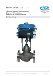
Operating Instructions
Pressure Controller Type „ROBOTER“
1.
Function
1.1
By the connection Z the controller is provided with air supply (free of dust, oil and water) of a
constant pressure of 1,4 bar (max. 2,0 bar). The connection Y is for the actuator, diaphragm
control valve, or the like. The supply air blows on a nozzle-flapper-system which is mounted to
a lever.
The constant-restrictor in the air supply line measures the air quantity out so that with open
nozzle the adjustable pressure at connection Y goes towards zero bar and with closed nozzle
towards 1,0 bar (max. 2,0 bar).
1.2
At the other end of the lever an adjustable reset spring is fastened. It increases or decreases
the feedback force in accordance with the lift position of the valve (with increasing force the
control circuit becomes lazier).
A setpoint spring secures the lever in its bearing. The bellows assembly consists of the bellows
and a pressure bolt, which are connected. If the pressure on the bellows increases, the lever
rises; if the pressure on the bellows decreases, the lever inclines.
1.3
With the design „increasing/increasing“ on increasing pressure the lever is pushed upwards by
the bellows so that air is stowed between nozzle and flapper. As a result the pressure Y increases.
1.4
With the design „increasing/decreasing“ the lever is pushed upwards by the bellows on increasing pressure so that air escapes between nozzle and flapper and the output pressure Y
drops.
1.5
A change of the setpoint value is effected by more or less biasing the setpoint spring.
In the output Y of the pressure controller is a damping throttle which has to be adjusted once at
the service place and by which the control speed of the actuator can be influenced in case of a
slight tendency to vibration of the control circuit.
2.
Start-up
2.1
The pressure controller is mounted to the actuator at the works.
Regarded in flow direction, the connection for the impulse line has to be arranged with the overflow plant before the control valve, with the reducing plant after the control valve.
The impulse line has to be laid in such way that condensate (with medium steam) can develop
before the bellows, e.g. by U-shaped or trumpet-shaped arrangement.
A shut-off device (valve or slide) has to be provided so that an exchange of defective bellows is
possible without stopping the whole plant.
2.2
With the basic adjustment of the controller -especially after exchange of bellows- it has to be
observed that the pressure screw part 29 always engages accurately in the counter bearing of
the measuring bellows part 35.
For this purpose the pressure screw has to be screwed into an extent that the bellows are biased by approx. 1,5 mm, and then it has to be countered with the nut part 31.
Code: 902BVE.DOC
Date of issue: 23. January 2001
902-BVe
ARCA-Regler GmbH D - 47918 Tönisvorst
Page 1 of 2
Operating Instructions
Pressure Controller Type „ROBOTER“
2.3
On the start-up the required air supply Z of minimum 1,4 bar (max. 2 bar) is adjusted at the air
pressure reducer. The air supply should be by approx. 0,2 bar higher than the max. operating
pressure of the connected actuator (see name-plate: control range).
2.4
After the adjustment of the controller it has to be checked, if the control equipment runs through
the whole range (e.g. lift of a control valve). If the required output pressure is not achieved, the
following has to be examined:
a) the air connections as regards leakage points
b) the constant-throttle with regard to soiling
After start-up or longer standstill the impulse chamber part 37 has to be air-vented by screw
part 39.
3.
Service instructions
3.1
As a complete control station, the pressure controller in connection with a control valve is independent of an outside service; only on air failure or breakage of the actuating diaphragm the
valve must be operated by the hand adjustment device.
3.2
If set value and actual value of the pressure in balanced condition of a control circuit do not coincide, by means of the setpoint spring the pressure can be increased by turning clockwise and
decreased by turning counter-clockwise. A change of the proportionality of the controller is
achieved by adjustment of the reset spring. A diminution of the active turns results in a greater
P-range and vice versa.
3.3
In case that still then the controller is restless, by turning-in the damping throttle (part 16) the
control pressure “Y” to diaphragm chamber can be damped (approx. 2.5 revolutions max.).
4.
Maintenance
At bigger intervals (depending on the air quality) the constant restrictor should be taken off and
cleaned by experienced personnel e.g. precision mechanics.
Code: 902BVE.DOC
Date of issue: 23. January 2001
902-BVe
ARCA-Regler GmbH D - 47918 Tönisvorst
Page 2 of 2


