1
www.swagelok.com
Remote Panel Mount Display
Model PTI-PM
Operating Instructions
Table of Contents
1. SAFETY REGULATIONS . . . . . . . . . . . . . . . . . . . . . . . . . . . . . . . . . . . . . . . . . . . . . . . . . . . . . . . . . . . . .3
2. INTRODUCTION
2.1 Accessing the programming buttons . . . . . . . . . . . . . . . . . . . . . . . . . . . . . . . . . . . . . . . . . . . . . . . . .4
3. ELECTRICAL CONNECTION
3.1. Terminal assignment . . . . . . . . . . . . . . . . . . . . . . . . . . . . . . . . . . . . . . . . . . . . . . . . . . . . . . . . . . . . 5
3.2. Connection data . . . . . . . . . . . . . . . . . . . . . . . . . . . . . . . . . . . . . . . . . . . . . . . . . . . . . . . . . . . . . . . . 5
3.3. Connecting an input signal . . . . . . . . . . . . . . . . . . . . . . . . . . . . . . . . . . . . . . . . . . . . . . . . . . . . . . . . 5
3.3.1. Connecting a 4 to 20 mA transducer in 3-wire technology . . . . . . . . . . . . . . . . . . . . . . . . . . . 6
3.3.2. Connecting a 0(4) to 20 mA transducer in 3-wire technology . . . . . . . . . . . . . . . . . . . . . . . . . 6
3.3.3. Connecting a 0 to 1 V, 0 to 2 V, or 0 to 10 V transducer in 3-wire technology . . . . . . . . . . . . 6
3.3.4. Connecting a 0 to 1/2/10 V or 0 to 50 mV transducer in 4-wire technology . . . . . . . . . . . . . . . 6
3.4. Connecting switching outputs . . . . . . . . . . . . . . . . . . . . . . . . . . . . . . . . . . . . . . . . . . . . . . . . . . . . . . 7
3.4.1. Connection with configured low-side switching output (NPN output, switching to GND) . . . . . 7
3.4.2. Connection with configured high-side switching output (PNP output, switching to +Uv) . . . . . 7
3.4.3. Connection with configured push-pull switching output . . . . . . . . . . . . . . . . . . . . . . . . . . . . . 7
3.5. Wiring of multiple PTI-PM digital indicators . . . . . . . . . . . . . . . . . . . . . . . . . . . . . . . . . . . . . . . . . . . . 8
4. CONFIGURING THE DEVICE
4.1. Selecting an input signal type . . . . . . . . . . . . . . . . . . . . . . . . . . . . . . . . . . . . . . . . . . . . . . . . . . . . . . 8
4.2. Measuring voltage and current (0 to 50 mV, 0 to 1 V, 0 to 2 V, 0 to 10 V, 0 to 20 mA, 4 to 20 mA) . . 9
4.3. Selecting output function . . . . . . . . . . . . . . . . . . . . . . . . . . . . . . . . . . . . . . . . . . . . . . . . . . . . . . . . 10
5. SWITCH POINTS AND ALARM BOUNDARIES
5.1. 2-point controller, 3-point controller . . . . . . . . . . . . . . . . . . . . . . . . . . . . . . . . . . . . . . . . . . . . . . . . . 12
5.2. 2-point controller with alarm function . . . . . . . . . . . . . . . . . . . . . . . . . . . . . . . . . . . . . . . . . . . . . . . . 13
5.3. Minimum/maximum alarm (individual or common) . . . . . . . . . . . . . . . . . . . . . . . . . . . . . . . . . . . . . 13
6. ZERO AND SPAN ADJUSTMENT . . . . . . . . . . . . . . . . . . . . . . . . . . . . . . . . . . . . . . . . . . . . . . . . . . . . . 14
7. MIN / MAX VALUE STORAGE . . . . . . . . . . . . . . . . . . . . . . . . . . . . . . . . . . . . . . . . . . . . . . . . . . . . . . . . 14
8. ERROR CODES . . . . . . . . . . . . . . . . . . . . . . . . . . . . . . . . . . . . . . . . . . . . . . . . . . . . . . . . . . . . . . . . . . 15
2
MS-13-PTI-PM-E
Rev 0 6-04-WEL
1. Safety Regulations
For proper and safe operation, the measuring device must be installed, operated, and serviced
according to NEC, local regulations, and these instructions. Otherwise, personal injuries or damage
or both can occur.
Only qualified persons should work on these devices.
1. Use within the conditions specified in the Swagelok General Industrial Transducer catalog.
2. Always disconnect the device from its power supply before opening it. Do not touch any of the
device’s contacts after installing.
3. The shield / ground connection must be wired to ground to protect the instrument from
electromagnetic disturbances.
4. If the device is visibly damaged or has been stored under inappropriate conditions,
turn off the device and do not use again.
MS-13-PTI-PM-E
Rev 0 6-04-WEL
3
2. Introduction
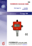
The Swagelok® PTI-PM remote panel mount display is a microprocessor-controlled device that supports one
universal interface for the connection of standard transducer signals (0 to 20 mA, 4 to 20 mA, 0 to 50 mV,
0 to 1 V, and 0 to 10 V) and frequency (TTL and switching contact).
The device features two switching outputs, which can be configured as 2-point controller, 3-point controller,
2-point controller with min-/ max-alarm or common / individual min-/ max-alarm.
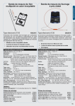
2.1 Accessing the programming buttons
Before the PTI-PM can be used, it has to be configured for the application.
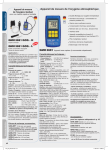
The device has three buttons that will be used during the configuration process.
■ Left button (Button 1) is used to confirm your entry
■ Center button (Button 2) is used to increase a value
■ Right button (Button 1) is used to decrease a value
Note: Buttons 2 and 3 will increase or decrease in value by one each time the button is touched.
If the button is held down, the value will increase or decrease quickly.
Button 1 Button 2 Button 3
There are two indicator lights to the far left and right of the three buttons.
■ Left indicator light displays the status of the first output
■ Right indicator light displays the status of the second output
Note: In order to avoid undefined input states and unwanted or wrong processes, we
suggest connecting the device’s switching outputs after the device has been configured
properly.
First output status
Second output status
To configure the PTI-PM, follow these steps:
1.
2.
3.
4.
5.
6.
7.
8.
4
Connect device to power supply.
Remove red front panel to access programming buttons.
Turn on power supply. The device will run its built-in test.
Enter the required input signals. (See section 4.)
Enter the required output signals. (See section 4.)
Turn off power supply.
Replace red front panel.
Connect device to electrical connection. (See section 3.)
MS-13-PTI-PM-E
Rev 0 6-04-WEL
3. Electrical connection
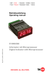
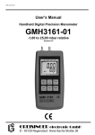
3.1. Terminal assignment
EASYBUS-Interface
10
EASYBUS-Interface
9
Input: 0 to 1 V, 0 to 2 V, mA, frequency, Pt100 Pt1000
8
Input: 0 to 50 mV, thermocouples, Pt100
7
Input: GND, Pt100, Pt1000
6
Input: 0 to 10 V
5
Supply voltage: GND
4
Supply voltage: +Uv
3
Switching output: GND
2
Switching output: 2
1
Switching output: 1
11 10 9 8 7 6 5 4 3 2 1
11
11 EASYBUS
10 EASYBUS
9 1V, mA, Freq., Pt100(0)
8 mV, TC, Pt100
7 GND, Pt100(0)
6 10V
5 GND, Supply -Uv
4 Supply +Uv
3 GND
2 Output 2
1 Output 1
Note: The contacts 3, 5, and 7 are connected internally.
3.2. Connection data
Supply voltage
Switching
output
1 and 2
NPN
PNP
Typical
Limitations
Between
Terminals
Min
Max
Min
Max
Notes
4 and 5
9V
28 V
0V
30 V
—
1 and 3,
2 and 3
—
—
—
30 V,
I < 1A
—
—
—
I < 200 mA
Not short
circuit
protected
0 mA
30 mA
—
Input mA
0 mA 20 mA
Input 0 to 1(2) V, Freq,
...
Input 0 to 50 mV, TC,
...
9 and 7
Input 0 to 10 V
0V
3.3 V
–1 V
8 and 7
0V
3.3 V
–1 V
6 and 7
0V
10 V
–1 V
4 V,
I < 10 mA
10 V,
I < 10 mA
20 V
—
—
—
Do not exceed the limit of the current and voltage.
3.3. Connecting an input signal
Do not exceed the limits of the input when connecting the device.
3.3.1. Connecting a 4 to 20 mA transducer in 3-wire technology
+
Supply
– 9 to 28 V (dc)
4
5
7
9
+Uv
–Uv
4 to 20 mA
transducer
+
–
Supply
for
transducer
with individual transducer supply
MS-13-PTI-PM-E
Rev 0 6-04-WEL
+
Supply
– 9 to 28 V (dc)
4
5
9
+Uv
–Uv
4 to 20 mA
transducer
without individual transducer supply
5
3.3.2. Connecting a 0(4) to 20 mA transducer in 3-wire technology
+
Supply
– 9 to 28 V (dc)
4
5
+Uv
Sig. 0(4) to 20 mA
transducer
–Uv
7
9
+
–
Supply
for
transducer
with individual transducer supply
+
–
Supply
9 to 28 V (dc)
4
5
+Uv
0(4) to 20 mA
Sig.
transducer
–Uv
9
without individual transducer supply
3.3.3. Connecting a 0 to 1, 0 to 2 V, or 0 to 10 V transducer in 3-wire technology
+
Supply
– 9 to 28 V (dc)
4
5
6
10 V
+Uv
Sig. Transducer
–Uv
7
+
Supply
– 9 to 28 V (dc)
4
5
6
10 V
7
+Uv
9
1V/2V
+
–
Supply
for
transducer
with individual transducer supply
9
1V/2V
Sig. Transducer
–Uv
without individual transducer supply
3.3.4. Connecting a 0 to 1/2 / 10 V or 0 to 50 V transducer in 4-wire technology
Supply
+
– 9 to 28 V (dc)
+
Supply
– 9 to 28 V (dc)
4
5
6
7
9
10 V
50 mV
1V/2V
+Uv
Sig+
Sig– Transducer
–Uv
+
–
Supply
for
transducer
with individual transducer supply
6
4
5
6
7
9
10 V
50 mV
+Uv
Sig+
1V/2V
Sig–
–Uv
Transducer
without individual transducer supply
MS-13-PTI-PM-E
Rev 0 6-04-WEL
3.4. Connecting switching outputs
The device features two switching outputs. There are three different operating modes for each switching output.
The operating modes are:
Low-Side:
“GND-switching” NPN output (open-collector)
The switching output is connected to the negative rail of the supply voltage
(connection 3 or 5) when active (switching output on).
High-Side: “+Ub-switching” PNP output (open-collector)
The switching output is connected to the positive rail of the supply voltage
(connection 4) when active (switching output on).
Push-Pull: The switching output is connected to the negative rail of the supply voltage
(connection 3 or 5) when inactive. When the switching output is active, it is
connected to the positive rail of the supply voltage (connection 4).
If one output is an alarm output, the output will be active in idle state (no alarm present). The output transistor opens or
the push-pull output changes from +Uv to –Uv when an alarm condition occurs.
Note: In order to avoid unwanted or wrong switching processes, connect the device’s switching outputs after you have configured the
device’s switching outputs properly.
Do not not exceed the limits of the voltage and switching outputs.
3.4.1. Connection with configured low-side switching output (NPN output, switching to GND)
+
1
2
+
1
Relay
–
2
5
+
–
–
Supply
for load
3
3
4
Relay
+
–
Supply
9 to 28 V (dc)
Connecting consumer loads (relay and lamp)
(without individual supply voltage)
3.4.2. Connection with configured high-side
switching output (PNP output, switching to +Uv)
Note:
Connections 3 and 5 are electrically connected internally.
When switching higher currents (greater than 50 mA),
the –Uv connection should not be attached to the device
(connection 3) but to the –Uv connection of the external
voltage supply to eliminate ground displacement.
4
+
5
–
Supply
9 to 28 V (dc)
Connecting consumer loads (relay and lamp)
(with individual supply voltage)
+
1
2
Relay
–
3
4
+
–
5
Supply
9 to 28 V (dc)
Connecting consumer loads (relay and lamp)
3.4.3. Connection with configured push-pull switching
output
+
1
2
Uin
Semicon.
relay
–
3
4
5
+
–
Supply
9 to 28 V (dc)
Connecting a semiconductor-relay
MS-13-PTI-PM-E
Rev 0 6-04-WEL
7
3.5. Wiring of multiple PTI-PM digital indicators
Inputs and outputs are not electrically isolated. When interconnecting several PTI-PM, make sure there is no
potential displacement.
Make sure to observe the following point:
■ When several PTI-PMs are connected to the same power supply unit, electrically isolate the transducers.
4. Configuring the Device
Note:
If you do not press any button for more than 60 seconds, the configuration of the device will stop.
The changes you have made will not be saved.
Note:
Buttons 2 and 3 feature a “roll-function.” Pressing button 2 once raises the value by one; pressing button 3 once lowers the
value by one. Pressing the button for longer than 1 second increases the counting speed. The device also features an
“overflow-function;” when reaching the upper limit of the range, the device switches to the lower limit, and vice versa.
4.1. Selecting an input signal type
■
■
■
■
Turn the device on and wait until it completes its built-in segment test.
Press button 2 for longer than 2 seconds. The device displays “InP” ('INPUT').
Use button 2 or button 3 to select the input signal (see table below).
Confirm the selection with button 1. The display will show “InP” again.
Depending on the selected input signal, additional configurations will be needed.
Input type
Voltage signal
Signal
0 to 10 V
0 to 2 V
0 to 1 V
To select
as Input
See
Section
U
4.2
I
4.2
Button 1
Button 2
Button 3
0 to 50 mV
4 to 20 mA
Current signal
0 to 20 mA
Note:
8
When changing the measuring mode “InP,” the input signal “SEnS,” and the measuring unit “Unit,“ all settings will be
changed to factory default. You have to set all the other settings, including the settings for zero and span adjustment
and switching points.
MS-13-PTI-PM-E
Rev 0 6-04-WEL
4.2. Measuring voltage and current (0 to 50 mV, 0 to 1 V, 0 to 2 V, 0 to 10 V, 0 to 20 mA, 4 to 20 mA)
This section describes how to configure the PTI-PM for measuring voltage or current signals from an external
transducer. You must select “U” or “I” as your desired input type, as explained in Section 4.1. The display has
to show “InP.”
■ Press Button 1. The display shows “SEnS.”
■ Select the desired input signal using button 2 or button 3.
■
■
■
■
■
■
■
■
■
■
■
■
Display
10.00
Input Signal
(Voltage Measuring)
0 to 10 V
2.00
0 to 2 V
1.00
0 to 1 V
0.050
0 to 50 mV
Display
4 to 20
Input Signal
(Current Measuring)
4 to 20 mA
0-20
0 to 20 mA
Confirm the selected input signal by pressing button 1. The display shows “SEnS” again.
Press button 1 again. The display will show “dP” (decimal point).
Select the desired decimal point place by pressing button 2 or button 3.
Confirm the selected decimal point by pressing button 1. The display shows “dP” again.
Press button 1 again. The display will show “di.Lo” (Display Low = low display value).
Use button 2 or button 3 to select the desired value the device should display when a 0 mA, 4 mA, or 0 V
input signal is attached.
Confirm the selected value by pressing button 1. The display shows “di.Lo” again.
Press button 1 again. The display will show “di.Hi” (Display High = high display value).
Use button 2 or button 3 to select the desired value the device should display when a 20 mA, 50 mV,
1 V, 2 V, or 10 V input signal is attached.
Confirm the selected value by pressing button 1. The display shows “di.Hi” again.
Press button 1 again. The display will show “Li” (Limit = measuring range limit).
Use button 2 or button 3 to select the desired measuring range limit.
Display
Measuring Input Limit
Note
Off
Deactivated
Exceeding the measuring range limit is tolerable for about 10 % of the selected
input signal.
On.er
Active (displays error)
The measuring range limit is bound by the input signal. When outside the input
signal, the device will display an error message.
On.rg
Active (displays the
selected limit)
The measuring range limit is bound by the input signal. When outside the input
signal, the device will display the selected lower / upper display value.
Note: When exceeding the measuring range limit greater than 10 % independently from the setting, the device will always
display an error message (“Err.1“ or “Err.2“).
■ Press button 1 to confirm the selection. The display shows “Li” again.
MS-13-PTI-PM-E
Rev 0 6-04-WEL
9
■ When pressing button 1 again, the display will show “FiLt” (Filter = digital filter).
■ Use button 2 or button 3 to select the desired filter [in sec.]. Selectable values: 0.01 to 2.00 seconds.
Note: When using the input signal 0 to 50 mV, a filter value of at least 0.2 is recommended.
Explanation: This digital filter is a digital replica of a low-pass filter.
■ Press button 1 to confirm your value. The display shows “FiLt” again.
Now your device is adjusted to your signal source. To adjust the outputs of the device:
■ Press button 1 again. The display shows “outP” (output).
To configure the outputs of the PTI-PM, please follow the instructions in Section 4.3.
4.3. Selecting the output function
■ After configuring the input (Section 4.2), you have to select the output function.
The display shows “outP” (output).
■ Use button 2 or button 3 to select the desired output function.
Function
Description
No output; device is used
as display unit
Output 1
Output 2
To select
as Output
See
Section
—
—
no
—
—
2P
5.1
3P
5.1
2-point-controller
digital
2-point controller
3-point-controller
digital
2-point controller
digital
2-point controller
2-point controller with
Min/Max alarm
digital
2-point controller
Min/Max alarm
2P.AL
5.2
Min/Max alarm
AL.F1
5.3
Min alarm
AL.F2
5.3
Min/Max alarm, common
Min/Max alarm, individual
—
Max alarm
■ Press button 1 to confirm the selected output function. The display shows “outP” again.
Depending on your output function setting, it is possible that one or more settings described
below will not be available.
■
■
■
■
■
10
When pressing button 1 again, the device will be displaying “1.dEL” (delay of output 1).
Use button 2 and button 3 to set the desired value [in sec.] for the switching delay of output 1.
Press button 1 to confirm the selection. The display shows “1.dEL” again.
When pressing button 1 again, the device will be displaying “1.out” (kind of output 1).
Use button 2 and button 3 to select the desired output function.
Display
Kind of Output
nPn
Low-Side
NPN, open collector, switching GND
PnP
High-Side
PNP, open collector, switching +Ub
Pu.Pu
Push-Pull
MS-13-PTI-PM-E
Rev 0 6-04-WEL
■ Press button 1 to confirm the selection. The display shows “1.out” again.
■ When pressing button 1 again, the device will display “1.Err” (preferred state of output 1).
■ Use button 2 or button 3 to set the desired initial state in case of an error.
Display
Kind of Output
Note
Off
Inactive in case of an error
Low- / High-side switch is opened in case of an error.
Push-Pull output is low in case of an error.
On
Active in case of an error
Low- / High-side switch is closed in case of an error.
Push-Pull-output is high in case of an error.
■ Press button 1 to confirm the selection. The display shows “1.Err” again.
■ If you selected a 3-point controller, the level 2 settings must be the same as level 1 settings.
“2.dEL” (delay of output 2), “2.out” (kind of output 2), “2.Err” (preferred state of output 2).
■ When pressing button 1 again, (only if you configured the device with min/max alarm), the device will display
“A.out“ (type of alarm output).
■ Use button 2 or button 3 to select the type of alarm output.
Display
Kind of Alarm Output
nPn
Low-Side
NPN, open collector, switching GND
Note
Switching output is closed (connected to GND) as long there
is no alarm condition and is opened if there is an alarm condition.
PnP
High-Side
PNP, open collector, switching +Ub
Switching output is closed (is under voltage) as long there is
no alarm condition and is opened if there is an alarm condition.
Pu.Pu
Push-Pull
Switching output is high with no alarm condition and changes to
low if there is an alarm condition.
Note:
The switching outputs are inverted when used as alarm outputs. This means as long there is no alarm condition,
the switching output will be active. In case of an alarm condition, the output will become inactive.
Note:
When using the output function “min / max alarm, individual“ the setting for type of alarm output is used for both alarm
outputs.
■ Press button 1 to confirm the selection. The display shows “A.out” again.
Depending on the selected output function, you have to make the settings for switching or alarm points.
See description in section “switch points and alarm boundaries” for further information.
Note: The settings for the switching and alarm points can be made later in an extra menu (see Section 5).
MS-13-PTI-PM-E
Rev 0 6-04-WEL
11
5. Switch points and alarm boundaries
■ Pressing button 1 for longer than 2 seconds will bring up the menu to select the switch points and alarm
boundaries.
■ Depending on the configuration you have made in the “output” menu, you will get different display values.
Please see the specific section for further information.
Function
Output 1
Output 2
To select
as Output
See
Section
—
—
no
No function
call possible
2-point-controller
digital
2-point-controller
—
2P
5.1
3-point-controller
digital
digital
2-point-controller 2-point-controller
3P
5.1
2-point-controller with
Min-/Max-alarm
digital
Min-/Max-alarm
2-point-controller
2P.AL
5.2
Min-/Max-alarm
AL.F1
5.3
Min-alarm
AL.F2
5.3
Description
No output; device is
used as display unit
Min-/Max-alarm,
common
—
Min-/Max-alarm,
individual
Min-alarm
5.1. 2-point controller, 3-point controller
This section describes how to configure the device as a 2-point or 3-point controller. You must have already
selected “2P” or “3P” as your desired output function.
■
■
■
■
■
■
Press button 1. The device will display “1.on” (turn-on point of output 1).
Use button 2 or button 3 to set the desired value. The device’s output 1 will turn ON.
Press button 1 to confirm your selection. The display shows “1.on” again.
When pressing button 1 again, the device will display “1.off” (turn-off point of output 1).
Use button 2 or button 3 to set the desired value. The device’s output 1 will turn OFF.
Press button 1 to confirm your selection. The display shows “1.on” again.
If you selected ‘2-point controller’, you are finished configuring your device. Press button 3 to switch over to
display the measuring value.
If you selected ‘3-point controller,’ please follow the instructions below.
■ Press button 1. The device will display “2.on” (turn-on point of output 2).
■ Use button 2 or button 3 to set the desired value. The device’s output 2 will turn ON.
■ Press button 1 to confirm your selection. The display shows “2.on” again.
■ When pressing button 1 again, the device will be displaying “2.off” (turn-off point of output 2).
■ Use button 2 or button 3 to set the desired value. The device’s output 2 will turn OFF.
■ Press button 1 to confirm your selection. The display shows “2.on” again.
Now you have finished configuring your device. Press button 3 to switch over to display the measuring value.
12
MS-13-PTI-PM-E
Rev 0 6-04-WEL
5.2. 2-point controller with alarm function
This section describes how to configure the device as a 2-point controller with alarm function.
You must select “2P.AL” as your desired output function.
■
■
■
■
■
■
■
■
■
■
■
■
■
■
Press button 1. The device will display “1.on” (turn-on point of output 1).
Use button 2 or button 3 to set the desired value. The device’s output 1 will turn ON.
Press button 1 to confirm your selection. The display shows “1.on” again.
When pressing button 1 again, the device will be displaying “1.off” (turn-off point of output 1).
Use button 2 or button 3 to set the desired value. The device’s output 1 will turn OFF.
Press button 1 to confirm your selection. The display shows “1.on” again.
When pressing button 1, the device will display “AL.Hi” (maximum alarm-value).
Use button 2 or button 3 to set the desired value. The device will turn on its maximum alarm.
Press button 1 to confirm your selection. The display shows “AL.Hi” again.
When pressing button 1 again, the device will display “AL.Lo” (minimum alarm value).
Use button 2 or button 3 to set the desired value. The device will turn on its minimum alarm.
Press button 1 to confirm your selection. The display shows “AL.Lo” again.
When pressing button 1 again, the device will display “A.dEL” (delay of the alarm function).
Use button 2 or button 3 to set the desired delay of the alarm function.
Note: The unit of the value will be in [sec.]. The device will turn on the alarm after the minimum or the maximum alarm
value was active for the delay time you have set.
■ Press button 1 to confirm the delay time. The display shows “A.dEL” again.
Now you have finished configuring your device. Press button 3 to switch over to display the measuring value.
5.3. Minimum/maximum-alarm (individual or common)
This section describes how to configure the device‘s alarm boundaries for min / max alarm monitoring.
You must have selected “AL.F1” or “AL.F1” as your desired output function.
■
■
■
■
■
■
■
■
Press button 1. The device will display “AL.Hi” (maximum alarm value).
Use button 2 or button 3 to set the desired value. The device will turn on its maximum alarm.
Press button 1 to confirm your selection. The display shows “AL.Hi” again.
When pressing button 1 again, the device will display “AL.Lo” (minimum alarm value).
Use button 2 or button 3 to set the desired value. The device will turn on its minimum alarm.
Press button 1 to confirm your selection. The display shows “AL.Lo” again.
When pressing button 1 again, the device will display “A.dEL” (delay of the alarm function).
Use button 2 or button 3 to set the desired delay of the alarm function.
Note: The unit of the value to be set is in seconds. The device will turn on the alarm after minimum or maximum alarm value
was active for the delay time you have set.
■ Press button 1 to confirm the delay time. The display shows “A.dEL” again.
Now you have finished configuring your device. Press button 3 to switch over to display the measuring value.
MS-13-PTI-PM-E
Rev 0 6-04-WEL
13
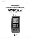
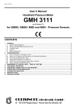
6. Zero and Span adjustment
The zero and span adjustment function can be used for compensating the tolerance of the transducer.
■ Turn on the device, and wait until it finishes its built-in segment test.
■ Press button 3 longer than 2 seconds. The device will display “OFFS“
(offset).
■ Use button 2 and button 3 for setting the desired offset value.
The input of the offset will be in digit °C / °F. The value that had been
set will be subtracted from the measured value. (See below for
Button 1 Button 2
further information.)
■ Press button 1 to confirm your selection. The display shows “OFFS” again.
■ When pressing button 1 again, the device will be displaying “SCAL” (scale = span).
■ Use button 2 and button 3 to select the desired span adjustment.
The span adjustment will be entered in %. The value displayed can be calculated like this:
Button 3
Displayed value = (measured value – zero point offset) * (1 + span adjustment [% / 100]).
Example:
The setting is 2.00 => the span has risen 2.00 % => slope = 102 %.
When measuring a value of 1000 (without span adjustment), the device would display 1020
(with span adjustment of 102 %).
■ Press button 1 to confirm the selection of the span adjustment. The display shows “SCAL” again.
Example:
Connecting a 4 to 20 mA pressure transducer
The device displays the following values (without zero or span adjustment): 0.08 at 0.00 bar
and 20.02 at 20.00 bar
Therefore you calculated:
You have to set:
zero point:
span:
deviation:
offset =
scale =
0.08
20.02 – 0.08 = 19.94
0.06 (= target span – actual span = 20.00 – 19.94)
0.08 (= zero point deviation)
0.30 (= deviation/actual span = 0.06/19.94 = 0.0030 = 0.30 %)
7. Min / max value storage
The device features a minimum/maximum value storage. In this storage, the highest and lowest performance
data is saved.
How to . . .
Details
Press button 3
The device will display “Lo” briefly. After that, the
min value is displayed for about 2 seconds.
Display the maximum value Press button 2
The device will display “Hi” briefly. After that, the
max value is displayed for about 2 seconds.
Display the minimum value
Erase the min/max values
14
Action
Press button 2 and 3 for The device will display “CLr” briefly. After that,
2 second displayed value the min / max values are set to the current.
MS-13-PTI-PM-E
Rev 0 6-04-WEL
8. Error codes
Err.1:
Exceeding the measuring range
Indicates that the valid measuring range of the device has been exceeded.
Err.2:
Possible causes:
• Input signal too high.
• Sensor shorted (0(4) to 20 mA).
Remedies:
• The error-message will be reset if the input signal is within the limits.
• Check transducer.
• Reset the counter.
Values below the measuring range
Indicates that the values are below the valid measuring range of the device.
Err.3:
Err.4:
Err.7:
Err.9:
Possible causes:
•
•
•
•
Input signal is too low or negative.
Current below 4 mA.
Sensor broken.
Counter underflow.
Remedies:
• The error message will be reset if the input signal is within the limits.
• Check transducer.
• Reset the counter.
Display range has been exceeded
Indicates that the valid display range (9999 digit) of the device has been exceeded.
Possible causes:
• Incorrect scale.
Remedies:
• The error message will be reset if the display value is below 9999.
• Check the scale setting, and reduce if necessary.
Values below display range
Indicates that display value is below the valid display range of the device (–1999 digit).
Possible causes:
• Incorrect scale.
Remedies:
• The error message will be reset if the display value is above 1999.
• Check the scale setting, and increase if necessary.
System error
The device features an integrated self-diagnostic function which checks essential parts of the device.
When detecting a failure, error message Err 7 will be displayed.
Possible causes:
• Operating outside of the valid temperature range.
• Device is defective.
Remedies:
• Stay within the valid temperature range.
• Exchange the defective device.
Sensor defective
The device features an integrated diagnostic function for the connected transducer.
When detecting a failure, error message Err 9 will be displayed.
Er.11:
Possible causes:
• Sensor broken.
Remedies:
• Check sensor or exchange defective sensor.
Value could not be calculated
Indicates a measuring value needed to calculate the display value is out of range.
Possible causes:
• Incorrect scale.
Remedies:
• Check settings and input signal.
MS-13-PTI-PM-E
Rev 0 6-04-WEL
15
Swagelok—TM Swagelok Company
© 2004 Swagelok Company
September 2004, R0
MS-13-PTI-PM-E