1
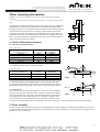
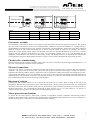
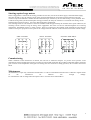
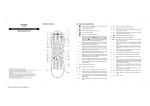
Operating instructions:
ATEK right angle
drive gear units
This operating manual is intended to help you to commission the ATEK drive in accordance with relevant regulations. The
stated features of our transmissions and the fulfilment of potential guarantee claims depend on compliance with these
directions.
Before the drive was shipped , it was subject to strict tests and was properly packed. Before starting operation , check for
transport damage. Report any damage to the transport company immediately.
If the transmission is not to be installed immediately, we request that you store it appropriately to its design in a dry place
without mayor temperature changes. For long-time storage (over 3 months) please refer to our special specification for storage
and preservation!
Lubrication
Please
refer
to
the
information
given
on
the
identification
plate
on
the
transmission!
Transmissions with lifetime lubrication have been factory fitted with the necessary amounts of lubricants. Subsequent
lubrication is only necessary when a substantial amount of lubricant has escaped due to leakage. The type and viscosity of
lubricant to be added must be obtained from the manufacturer whilst stating the serial number of the transmission.
Transmissions for oil change lubrication are delivered without lubricant and must be filled before commissioning with an oil or
grease in accordance with our lubricant recommendation.
Assembly
The transmissions should always be installed according to the fitting position that has been ordered.
The gear unit should be set up on appropiate solid foundations or mounted as a flange drive directly on the machine to be
driven. The shaft ends have to be aligned very carefully for quiet running and safety during operation. To compensate for minor
mounting inaccuracies we recommend the use of elastic couplings. The couplings must be warm or must be mounted with the
aid of D-centring and a screw. Do not hammer! This will avoid damage to the tooth profile, rolling bearings and locking rings.
Plug-in transmissions can be fitted directly onto the shaft of the driven machine. For flange gears it is important that the
attachment surface is it excact right angles to the machine shaft's axis. Otherwise the bearings will suffer too much stress and
might be damaged. The reaction torque corresponding to the output torque can be supported with a torque converter bearing.
The bar should be mounted on the gears' machine side in order to prevent additional bending stresses. Do not mount the gears
directly on a foundation plate when the machine shaft is bedded near the gears.
For hollow shafts with a shrunk-on flange, please additionally refer to our assembly instructions for shaft-hub-connections.
1
Motor mounting information
Commercially available standard three-phase motors of the IEC 72-2 / DIN 42677
unfortunately do not always correspond to the valid industry standards. Before
assembly, the motor is to be checked for radial divergence of the shaft and also for
coaxial deviation and axial run-out of the flange. With transmissions from the
VLM series (hollowed drive shaft for the direct insertion of the motor shaft) we
recommend striving for the following values of DIN 42955 R. Higher deviations
lead to an increased load on the bearings and the teeth. These increased loads can
cause a premature transmission failure.
l/2
Bild 1.
d
1. Check of the motor tolerances
d
Warning: You may only assemble the motor if you have carefully read through the mounting
instructions
on the back of this page and understood them and if you are authorized and have proper
skills !
1.1 Concentricity of the shaft end
l/2
Table 1 (DIN 42955)
Diameter of the
cylindrical shaft end d
up to 10
10 to 18
18 to 30
30 to 50
50 to 80
Concentricity tolerance
N (normal)
R (reduced)
0,03
0,015
0,035
0,018
0,04
0,021
0,05
0,025
0,06
0,03
Pic. 1
Bild 1.
Mounting flange
Centering diameter b1
40 to 100
100 to 230
230 to 450
Coaxiality tolerance and run-out tolerance
N (normal)
R (reduced)
0,08
0,04
0,1
0,05
0,125
0,063
1.3 Run-out tolerance of the flange surface to the axis of the shaft end
It is recommended to measure with the shaft in the vertical position in order to
eliminate the gravitational influence of the shaft on the measuring instrument.
Pic. 2
b1
Bild 2.
10±1
Table 2 (DIN 42955)
10±1
1.2 Coaxiality tolerance for the centering shoulder
Pic. 3
b1
1.4 Axial run-out
This is measured on the radius equivalent to the sum of the outside diameters,
the pitch circle diameter and the bolt holes. In order to eliminate the influence
Bild 3.
of an axial displacement of the shaft, the measurement must be repeated after
the actuating arm has been offset through 180° in relation to the shaft. The
mean value from the two measurements is decisive for the evaluation of the
accuracy. It is recommended to measure with shaft in the vertical position in order to eliminate the play in the axial bearing.
2. Motor assembly
The motor shaft and the transmission shaft are to be cleaned before assembly. Height and width of the parallel key on the motor
are measured and compared with the dimensions of the hollowed drive shaft. Deformation on the motor shaft, the flanges or the
parallel key are to be reworked.
2
To avoid frictional corrosion, the motor shaft and the transmission shaft are to be treated with a separating agent. The position
of the parallel key/parallel key groove is to be aligned such that the drillings of the mounting flanges are almost congruent.
If necessary, the motor or the transmission is fitted vertically with the use of a lifting gear. The parallel key connection must be
able to be fitted together without notable resistance. Wedging of the two parts and impacts on one of the two drive components
are to be avoided as they can cause premature transmission failure. The mounting holes of the connecting flanges are to be
aligned to each other. For ease of assembly, we recommend to loosening the motor brake on larger drive units. Before
tightening the flange connection, checks should be made by means of measuring shims, to ensure that the two flange surfaces
are touching on their entire circumference. Only then should the fixing bolts are to be tightened crosswise.
Motor mounting play-free, elastic couplings
The axial, play-free plug-in shaft coupling with integrated frictionally engaged shaft-to-hub connections, permits a simple blind
assembly and consists of 3 parts:
1. Conical hub, already mounted on the drive shaft of the transmission.
2. Plastic involute annular gear
3. Clamping hub type KN or KNN or clamping ring hub (2 parts) type SN
The power is transmitted by frictional engagement between the functional surfaces. With type KNN an additional interlocking
is achieved with the use of a parallel key. Particular attention must be paid to the controlled tightening of the locking screws or
draw spindles and to the condition of the contact surfaces. Tolerance for fitting of motor shaft - hub k6/H7. The torques
indicated in the catalogue may change with other shaft tolerances – please contact ATEK – Technique for further information.
Assembly of clamping hub on to the motorshaft
Clean and degrease the hub bore and the shaft.
Release the clamping srew slightly – push the hub onto the shaft – measure dimension A
at the gear unit - adjust dimension B (from table 3). Tighten the clamping screw with the
tightening torque indicated in table 1.
Table 1
Size of coupling
Diameter D [mm]
Clamping screw DIN 912
Pulling torque TA [Nm]
14
30
M3
1,34
19/24
40
M6
10,5
24/28
55
M6
10,5
28/38
65
M8
25
38/45
80
M8
25
Assembly of clamping ring hub on to the motorshaft
Clean the hub bore and the shaft and oil them afterwards with liquid oil (e.g. with
Castrol 4 in 1).
Caution: Do not use oil and grease with molybdenum disulphide or other high
pressure additions as well as sliding grease pastes.
Release the clamping screws slightly and pull of the clamping ring slightly from the
hub, so that the clamping ring is released. Push the clamping ring hub on to the
motorshaft - measure dimension A at the gear unit - adjust dimension B ( from table
3). Tighten the clamping screws crosswise and evenly until the tightening torque
indicated in table 2 is reached. Repeat this until all clamping screws reach this
tightening torque.
Table 2
Size of coupling
Diameter D [mm]
Clamping screws
Pulling torque TA [Nm]
14
30
4xM3
1,34
19/24
40
6xM4
2,9
24/28
55
4xM5
6
28/38
65
8xM5
6
38/45
80
8xM6
10
øD
S
3
Servomotor
A
A
B
Typ VC
Typ SLC
Table 3
Size of coupling
Diameter D [mm]
Distance dimension S
Dist. dimension B = (A - S)
14
30
1,5
A - 1,5
19/24
40
2
A-2
24/28
55
2
A-2
28/38
65
2,5
A -2,5
38/45
80
3
A-3
Gear motor assembly
The installation in hazardous locations is not permitted, except with motors that have the appropriate approval. The supplied
type of protection and thermal class are to be compared with the conditions in the place of installation. A stoppage heating is
recommended for locations that have a large variation in temperature or high air humidity. Attention has to be paid to sufficient
admission of fresh air and unobstructed cooling fins as well as open air intakes an outlets on the ventilator. The distance
between the air inlet opening and the nearest wall should be equivelent to at least half the diameter of the motor. For vertical
mounting with the ventilator mounted above the motor, we recommend ventilator cover or a cover integrated into the
equipment. The foundation work must be executed evenly, cleanly and durably and has to be dimensioned to withstand the
occuring moments of torques. Misalignment in the drive system, as well as shock and unbalanced parts must be avoided.
Checks before commissioning
Before commissioning the insulation resistance of the engine coils must be checked. It should be higher than 5MΩ at 25°C. If
this value is not achieved, a specialist must be consulted.
Electrical connections
The motor may only be connected by competent personnel. The electrical connection must correspond with the valid safety
regulations. The power and current data must correspond with the data of electrical mains supply. Voltage and frequency
fluctuations are subject to DIN EN 60034-1. 50Hz motors can be connected to a 60Hz mains supply if the change in the power,
voltage, torque and number of r.p.m. are considered. All cross-section of all connecting cables must be adequately dimensioned
(DIN VDE 0298). The grounding connection is located in the proximity of, or directly in the terminal box. Cable entries are to
be provided with screwed connections according to DIN 46320/T1.
Direction of rotation
Transmissions with standard motors can be connected in both directions of rotation. When viewing the the end of the
transmission shaft, the direction of rotation “right“ means that the shaft is turning in the clockwise direction. For checking the
direction of rotation, the drive should be operated first in its installation position without any machine parts connected (refer to
the fitting instructions). We recommend first connecting the phase sequence L1, L2, L3 to the clamps U1, V1 and W1. A
change to the direction of rotation can subsequently be made swapping any two cables.
Motor-protection mechanisms
To protect the drive unit against a short-circuit, overload or single-phase operation, sufficiently dimensioned protective
switches or fuses with thermal overcurrent relays should be fitted. Installed PTC feelers (thermistors) are to be connected to a
suitable actuating device. Thermostats are prewired for automatic switching.
4
Starting squirrel cage motors
If direct engagement is selected as the starting procedure for the drive, the electrical mains supply connected and the supply
lines must be able to carry the starting current. If the connected machine does not need an increased starting torque (the
resistive torque of the machine is smaller than the rated load torque of the drive), the star-delta starting is to be preferred. This
avoids the strong initial jolt and with frequent starting procedures, the life span of the drive is increased. The starting current
and the starting torque are approx. 30% lower than during direct engagement.
The switching of the star into the delta connection should be made at approximately the nominal motor speed. Otherwise, the
switching current is almost as large as during direct engagement. The motoe can also be started through the use of starting
transformers, intermidiate resistors or stator resistors. These are connected to the terminals of the terminal box and cause the
reduction of torque in proportion to the square of the voltage and of the reduction of the nominal current linear with the voltage.
STAR - Connection
W2
U2
V2
U1
V1
W1
L1
L2
L3
DELTA - Connection
W2
U1
L1
U2
V2
V1
L2
W1
Connection: STAR- DELTA
W2
U2
V2
U1
V1
W1
L3
Commissioning
Where ventilation of the transmission is desired, the vent hole is sealed for transport. To prevent excess pressure in the
transmission an hence leakage the locking screw must be removed and replaced by the provided venting filter before setting the
gear in motion. If the temperature of the gear box housing does not exceed 50°C during operation, the vent filter must not be
fitted.
Maintenance
All ATEK drives require only a minimum of maintenance. For drives with lifetime lubrication this is reduced to regular checks
of
the
transmission
for
lubricant
loss
through
leakage.
For transmissions with oil change lubrication please refer to our lubricant recommendation.
5