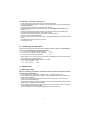
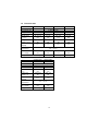
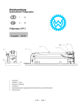
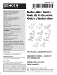
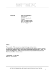
1
Operating Instructions
Rerailing Equipment
84072/0000-85N GB
Issue 1.2005
Double-acting
Telescopic Cylinders
replaces issue 9.2004
1
Contents
1
2
3
4
5
6
7
8
9
10
11
12
13
14
15
Page
Safety instructions
3
Organizational measures
3
General safety instructions
4
Instructions for maintenance and service
5
Function of individual components
5
5.1
General
5.2
Coupling connectors
5.3
Hoses between control desk and cylinders
5.4
Quick-connect couplers
5.4.1
Hose pair acc. to 84072/1765
5.4.2
Single hose, red
5.4.3
Connection of quick couplers
Initial Commissioning
7
Installation
7
7.1
Safety notes
7.1.2
General instructions for the installation / operation of the cylinders
7.1.3
Note for retracting the cylinder
Hydraulic connection and operation
8
8.1
General
8.1.1
Connection of telescopic cylinders
8.2
Operation of cylinders
Zubehör
8
9.1
Base plates
9.1.1
Mounting the base plates
9.2
Stacking sets
9.2.1
Attributes of stacking sets
9.2.2
Installation / operation of the stacking sets
Dismantling of components
9
Maintenance
9
11.1
Mechanical check
11.2
Hydraulic system leakage
11.3
Cylinder components
11.4
Oil recommendation
Problems / trouble shooting
10
Repair
11
Hydraulic diagram
11
Technical data
12
2
1 Safety instructions
Basic operation and designated use of the machine
1.1 The cylinders described below may only be used in combination with components from
LUKAS rerailing equipment. It is possible to operate them with devices from other manufacturers
-- however, this requires technical testing/approval by LUKAS in each individual case.
1.2 The machine is intended exclusively for driving and controlling rerailing equipments. Any
other use, e.g. driving and controlling other hydraulic equipment, is not according to specifications.
The manufacturer/supplier will not accept any liability for damage as a result thereof. The risk is
entirely to be borne by the user.
Use according to specifications also means that the operating instructions are observed and that the
conditions for inspection and maintenance are to be met (see also chapters 4 and 13).
1.3 The machine has been built in accordance with state-of-the-art standards and the recognized
safety rules. Nevertheless, its use may constitute a risk to life and limb of the user or of third parties,
or cause damage to the machine and to other material property.
1.4 The machine must only be used in technically perfect condition in accordance with its
designated use and the instructions set out in the operating manual, and only by safety-conscious
persons who are fully aware of the risks involved in operating the machine. Any functional disorders,
especially those affecting the safety of the machine/plant, should therefore be rectified immediately.
1.5
Device designation
HP
25
T
min. push capacity
in tonnes
high-pressure
cylinder
telescopic design
-
450
R
total stroke
in mm
hydraulic piston
retraction
2 Organizational measures
2.1 The operating instructions must always be at hand at the place of use of the machine, e. g.
by stowing them in the tool compartment or tool-box provided for such purpose.
2.2 In addition to the operating instructions, observe and instruct the user in all other generally
applicable legal and other mandatory regulations relevant to accident prevention and environmental
protection. This also applies for wearing protective clothing, helmet with visor or goggles and
protective gloves.
2.3 In order to avoid injuries, the machine must only be operated by a specially trained operator who
has undergone safety training. It is also important to consider the influence of stress factors on the
operator when working at the machine. These may constitute a risk to life and limb of the user or of
third parties, or cause damage to the machine and to other material property.
2.4 Observe all safety instructions and warnings attached to the machine. Make sure that safety
instructions and warnings attached to the machine are always complete and perfectly legible.
2.5 Never make any modifications, additions or conversions which might affect safety without the
supplier’s approval. This also applies to the installation and adjustment of safety devices and valves
as well as to welding work on load-bearing elements.
3
2.6 Spare parts must comply with the technical requirements specified by the manufacturer. Spare
parts from original equipment manufacturers can be relied to do so. It is only allowed to use
original LUKAS spare parts or LUKAS system components.
2.7 Replace hydraulic hoses within stipulated and appropriate intervals even if no safety-relevant
defects have been detected. This has to be done after 10 years at the latest.
2.8 Adhere to prescribed intervals or those specified in the operating instructions for routine checks
and inspections.
2.9 Make sure to dispose properly of packing material and dismounted parts!
3
General safety instructions
3.1 Check all parts for possible damage before starting up.
3.2 When operating the machine, pay attention to the ambient conditions, making sure that you
wear suitable personal protective clothing. Also pay attention to the fact that the cylinders could heat
up after a while. They may also cool down considerably depending on the ambient conditions. This
must likewise be borne in mind by wearing suitable protective clothing.
3.3 Also be aware that possible noise could result from various sources during operation which may
impede communication.
During operation, there may also be impairment from exhaust fumes. Make sure that there is sufficient
ventilation or that protective measures are taken.
Since the cylinders are coupled with hose pipes, they may constitute a tripping risk. Ensure that the
hose pipes are safely installed. This is especially important due to the fact that escape routes must
be provided.
3.4 When working, make sure there is sufficient lighting and a clear view of the machine, so as to
guarantee safe working conditions.
3.5 Before switching on/starting up and while operating the machine, please ensure that nobody
will be endangered when the machine starts running. Also, secure the machine against unauthorised
or accidental switching on/off.
3.6 In the event of malfunctions, stop the machine immediately and lock it. Have any defects
rectified immediately.
3.7 Before setting the machine in motion always check that the accessories have been safely
stowed away! During transport, the weight of the LUKAS telescopic cylinders must be taken into
account.
3.8 Avoid any operation that might be a risk to machine stability! For this reason, a base plate (refer
to chapter 9.1) must be used. Also check that the foundation has sufficient load-bearing capacity.
3.9 Check the machine at least after every operation for obvious damage and defects. Report any
changes (incl. changes in the machine’s working behaviour) to the competent organization/person
immediately. If necessary, stop the machine immediately and lock it. All lines, hoses and screwed
connections have to be checked for leaks and obvious damage. Repair damage immediately.
Splashed oil may cause injury and fire.
3.10 All safety equipments have to be checked for completeness and flawless condition:
- instruction markings and warning signs (safety instructions)
- check safety cover (e.g. motor-safety covers, heat protection etc.) if they are available and if they
are in a good condition.
4
3.11 Working under loads is not allowed if they are only lifted by hydraulic cylinders. If the work
is indispensable sufficient mechanical supports are needed additionally.
3.12 Make sure that hoses are not mechanically stressed (pulling, bending etc.).
3.13 When working in the vicinity of live components and cables, it must be ensured that
precautions are taken to avoid current conductions or high-voltage flashing over to the motor
pump.
3.14 During use of cylinder unit, the creation of electrostatic charges which could result in sparking
must be prevented.
3.15 When mounting the cylinders the power unit should always be placed in such a way that its
function and safety will not be impaired by strong external temperature influences.
4
Instructions for maintenance and service
4.1 For the execution of maintenance and service work, tools and workshop equipment adapted to
the task on hand are absolutely indispensable.
Work on the hydraulic system must be carried out only by personnel having special knowledge and
experience with hydraulic equipment.
4.2 Before putting into operation clean the machine, especially connections and threaded unions,
of any traces of oil, fuel or preservatives before carrying out maintenance/repair. Never use
aggressive detergents. Use lint-free cleaning rags and pay attention that the components are
meticulously clean during reassembling after repair.
4.3 During dismantling of machines it is necessary to collect the outrunning hydraulic liquids
completely, so that they cannot reach the ground. They have to be disposed properly according to
the instructions.
4.4 Always tighten any screwed and thread connections that have been loosened during maintenance and repair. Observe the stipulated torques.
4.5 Aggressive material (acid, lye, solvent, vapour) can damage the machine. It is necessary to
clean the whole machine if it must be exceptionally operated under such conditions or gets into touch
with these materials. Additionally, the machine must be checked as described under 3.9.
Please refer to our separate booklet "Safety instructions for hydraulic hoses" 84150/8065-85
(delivered with hose)!
5
Function of individual components
5.1 Gerneral
LUKAS Telescopic cylinders are equipped with several pistons one fitting into the other among
which the total stroke is divided.
Characteristics:
- Small overall size in relation to stroke.
- Different lifting capacity in the individual stages due to different piston diameters.
Please observe the max. lifting capacity of the different pistons with a view to the max.
permissible load of support blocks used with the cylinder. This especially applies to the
permissible load for shifting devices of LUKAS rerailing equipment.
- Max. working pressure is 53 MPa (530 bar).
5
5.2
Coupling connectors
Apart from the coupling connectors, these cylinder models are also provided with two connector
blocks with a safety valve, thus preventing damage to the cylinder in the event of external loads.
If pressure exceeds the maximum permissible value, the safety valve will open automatically, and
oil will squirt out (protected).
5.3
Hoses between control desk and cylinders
Those are normally connected via 10 m long hose pairs (red/blue, ref. 84072/1765). All hoses
are duly colour marked and equipped with quick couplers in non-interchangeable design:
- connection to A (= extension)
red,
- connection to R (= retraction)
blue.
5.4
Quick-connect couplers
5.4.1 Hose pair red/blue 84072/1765
The hose couplings of this hose pair are equipped with a „quick-stop“ function which will block the
oil reflow from the cylinder if, for example, a hose breaks, thus preventing the load from being
dropped. When lowering a very heavy load or when switching the control valve to „lowering“ position
too quickly, the quick-stop may catch without there being a necessity for it. Then the cylinder can
no longer be retracted. In this case switch the selector valve to „lifting“ again until the cylinder starts
to extend. Carefully start the lowering procedure again.
5.4.2 Single hose, red
The quick-stop feature is optional for this hose. It requires the use of the StMu 61-M coupling sleeve
(colour silver or yellow).
5.4.3 Connection of quick couplers
- Remove dust protection covers.
- Unlock connect socket with adjusting ring by turning it.
- Retract sleeve and connect plug and socket while holding the sleeve in this position.
- Release sleeve and lock adjusting ring: showglass is “RED”.
The connection has now been made and secured.
6
Note regarding the modified release mechanism as of June 2004
When connecting the hoses, be aware of the following basic functions of the quick couplers:
X
Y
Before coupling unlock the connect socket by turning the sleeve into position X. Retract sleeve
and connect plug and socket. Release sleeve and turn it into position Y.
Now the connection has been made and locked. Uncoupling is done in the reverse order.
Connection of the hoses is possible only, when they are depressurized.
In order to prevent contamination of the tool lines protect the couplings with delivered dust caps.
Attention
Quick-connect couplers partly have special functions. Therefore it is not allowed screwing off
them from the hoses or to exchange them!
To avoid pollution, the dust protection covers must be put on plug and socket if the couplings are
not connected. The dust protection covers must be connected to each other if the couplings are
connected.
6
Initial commissioning
Prior to commissioning the cylinders must be vented !
- Extend pistons without load approximately halfway.
- Turn cylinder upside down, the highest point of the cylinder must be lower than the the valve
block on the power unit.
- Extend pistons about twice by means of the corresponding valve so that air can escape from
cylinder and hoses.
7
Installation
7.1 Safety notes
7.1.1 Prior to installation of the cylinder, the load to be lifted must be properly secured against
rolling off in accordance with the applicable guidelines of the user’s country. Always observe the
load while moving it by means of a cylinder!
Do not stand below suspended loads. If in exceptional cases this cannot be avoided, these loads
must mechanically be sufficiently secured against movement in any direction!
7.1.2 General instruction for the installation / operation of all cylinders
- Put the cylinder on a level, non-slip surface, (Attention: hydraulic oils may cause slippery films
on the ground!)
- The area of support must be a continous level surface (not a grating, gravel, etc.).
- Never put cylinders on a yielding support.
- Never use cylinders without piston guard plate in order to avoid damaging the piston and to
assure safe application of the force.
- Always use wooden supports between the piston guard plate and the jacking point.
- Always use LUKAS base plates (see accessories, chapter 9).
- Observe centred load initiation on the pistons ! If necessary try to find a better load
application point.
7
7.1.3 Note on retracting the cylinder
The load may only be lowered with the pump running. Otherwise a vacuum could be created which
would cause air to enter the hydraulic system.
8
Hydraulic connection and operation
8.1 General
Prior to connecting the hoses carry out correct cylinder installation as per chapter 7. Make sure that
the pump is switched off!
8.1.1 Connecting the telescopic cylinders
As described in chapter 5.3, first connect the blue hose, then the red hose of the pair of hoses.
8.2 Operation of cylinders
Operate the cylinders as per operating manual of the power unit delivered with the cylinders.
9
Accessories
9.1 Base plates
Base plates are designed to:
- enlarge the floor space of the cylinder,
- increase static stability,
- level out unevenness of the ground.
9.1.1 Mounting the base plates
Put cylinder on the base plate in such a way that the coupling connector meshes with groove of the
guide collar. Tighten the three srews on the guide collar. Now the cylinders can be carried together
with the base plate.
9.2 Stacking sets
9.2.1 Attributes of stacking sets
Multistage sets prolong the stroke of a cylinder. For space reasons, cylinders with large strokes
often cannot be used due to their large overall height. Multistage sets make it possible to use
cylinders with small overall height to lift loads very high.
Generally multistage sets consist of:
- cylinder attachments
- piston attachments
- piston protection plate
- forked lever.
8
9.2.2 Installation / Operation of stacking sets
- Lift the load with the cylinder using the normal piston guard plate.
- Place the first stacking ring (item 7) centrally on the cylinder body by means of the forked lever.
Caution under load!
- Lower the load onto this stacking ring and retract the piston.
- Remove the standard piston guard plate from the cylinder. Caution under load! (refer to
chapter 7.1.1,).
- Place the first piston plate (item 8) centrally onto the piston body (using a forked lever).
- Completely extend the load again by means of the piston.
- Insert the second stacking ring (item 9) by means of the forked lever.
- Lower the load onto this stacking ring.
- Insert the nose of the second piston platein the corresponding hole of the first plate (use fork
lever!).
- Completely lift the load by means of the piston.
- Continue in this way...
10
Dismantling of components
For dismantling of the components reverse the installation sequence. Before final dismantling of
the devices it is absolutely necessary to ensure that:
——> the load is in a stable, immovable position,
<——
——> the drive motor/engine must be shut down,
<——
——> all hoses have been depressurized:
<——
-
Switch selector valve on the power unit temporarily to “LOWERING”(pressure relief of hoses),
then switch back to the centre position.
Disconnect the DEPRESSURIZED hoses in this order: :
——> hose, piston side
red,
——> hose, rod side
blue.
11 Maintenance
11.1 Mechanical check
After each operating procedure the components must be checked for faultless operation
(clean them first if necessary):
- Check whether each single piston retracts smoothly (cylinders/pistons O.K.?),
- Check whether there are any loose hydraulic screw connections on the devices and hoses;
tighten them if necessary.
- Check the mechanical parts, the valves and the hoses of power pack, control table and
cylinders for mechanical damage.
- Check whether the signs, warnings, operation and control symbols and other markings (colour
markings) are complete and perfectly legible.
- Check whether all safety covers (engine: protective cover, exhaust pipe cover), hoop guard
etc. are available and in perfect condition.
- Check the condition of the accessories (baseplates, header plates, etc.).
9
11.2
-
Hydraulic system leakage
Check devices for oil loss and replace defective seals if necessary.
Important:
Carry out the following procedures over an oilpan; dispose of used oil!
11.3
Cylinder components
To remove the oil remaining in the piston main zone and piston ring zone, unscrew both couplings
from the connecting blocks if necessary and wait until all of the oil drains.
Then flush and fill up fresh hydraulic oil. Screw couplings in and tighten them to 45 Nm torque. Vent
cylinders acc. to chapter 6!
Remark:
Please note that the oil filling must be completely flushed and replaced by another type of oil if there
is a significant change in the operating conditions (ambient temperatures). Also refer to the
following chapter.
11.4
Oil recommendation
Oil for LUKAS hydraulic devices: Mineral oil in accordance with DIN 51524 and others
A
B
C
D
E
Range of oil temperature
- 24 ... + 30 °C
- 18 ... + 50 °C
- 8 ... + 75 °C
+ 5 ... + 80 °C
- 8 ... + 70 °C
Viscosity rating
HL 5
HLP 10
HLP 22
HLP 32
HF - E 15
Remarks
biodegradable
2
recommended viscosity range: 10 ... 200 (mm /s).
12 Problems / Trouble shooting
Index: P = Problem;
S = Symptom;
F: Cylinder pistons cannot be retracted
S: red hose on the piston side is pressurized
—> quick-stop has been activated;
switch selector vlave to "lifting" for a moment and carefully start lowering again.
P: Hose couplings cannot be connected
S: red hose on the piston side is pressurized
—> hoses are under pressure since they have accidentally been disconnected without being
depressurized
- open union nut on hose, cover against oil spray,
- Hose is depressurized; pay attention to squirting oil,
- tighten union nut again (MA = 45 Nm).
10
If the faults cannot be rectified, notify an authorized LUKAS dealer or LUKAS Customer Service
direct at the following address: LUKAS Hydraulik GmbH, Weinstraße 39, 91058 Erlangen,
Germany; P.O. Box 25 60, 91013 Erlangen, Germany;
Customer Service tel.: +49 (0) 91 31/69 83 48; fax +49 (0) 91 31/69 83 53.
13 Repair
In all system components only genuine LUKAS spare parts as listed in the spare parts list may
be replaced, since for that purpose it is absolutely necessary to consider special tools, assembly
notes, safety aspects and checks that might be required. See chapter 2.6 and 4 of Safety
instructions.
14 Hydraulic Diagram
11
15 Technical data
Order no.
Permissible load
Length, extended
Total stroke
Stroke piston
1/2/3
Lifting force
piston 1 / 2 / 3
Required oil
capacity
Ambient
temperature
Dimensions
dia. x height
Weight
Order no
Permissible load
Length, extended
Total stroke
Stroke piston
1/2
Lifting force
piston 1 / 2
Required oil
capacity
Ambient
temperature
Dimensions
dia. x height
Weight
HP10/T280R
84072/4665N
493
278
90 / 94 / 94
mm
650 / 301 / 104
kN
1.4 l
HP25/T185R
HP25/T450R
84072/1565N
84072/3765N
53 MPa (530 bar)
399
830
184
450
95 / 89
223 / 227
mm
mm
650 / 301
650 / 266
kN
kN
1.3 l
HP50/T185R
84072/8265N
419
185
89 / 96
mm
1066 / 504
kN
2.8 l
2.0 l
dia. 170 x 380
mm
23.8 kg
dia. 220 x 234
mm
25 kg
-20 ... +55 °C
dia. 170 x 215
mm
14.8 kg
dia. 170 x 215
mm
14.8 kg
HP50/T400R
HP65/T400R
84072/8065N
84072/1065N
53 MPa (530 bar)
799
797
399
397
195 / 204
198 / 199
mm
mm
1066 / 504
1665 / 703
kN
kN
4.3 l
7.0 l
-20 ... +55 °C
dia. 220 x 400
mm
41.6 kg
dia. 270 x 400
mm
61.1 kg
12
© Copyright 2002 LUKAS Hydraulik GmbH
LUKAS Hydraulik GmbH
A Unit of IDEX Corporation
Weinstraße 39, 91058 Erlangen • Germany
Postfach 2560, 91013 Erlangen • Germany
Telefon: +49(0)9131/698-0 • Telefax: +49(0)9131/698-394
e-mail: [email protected]
Tel_Zyl_LAA_Ag105_e.P65
13
Subject to revision