1
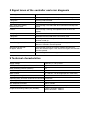
GEIGER-Funk
Sunshade controls
Blind Controller
for 230V drives
GFJ006
GFJ007
GFJ009
Installation and Operating
Instructions
d
e
d
o
c s
e m
r
p te
r
fo sys
Table of Contents
1
2
3
4
Introduction........................................................................................................................................3
Safety Instructions .............................................................................................................................3
Intended Usage .................................................................................................................................3
Connection and installation ...............................................................................................................4
4.1
4.2
Circuit diagram GFJ006 .........................................................................................................4
4.4
Plug-in version GFJ009 as control GFJ009 ...........................................................................4
4.3
5
6
Installation instructions ...........................................................................................................4
Plug-in version GFJ007..........................................................................................................4
Set-up ................................................................................................................................................4
Extensions and individual settings ....................................................................................................5
6.1.
Teaching in radio commands .................................................................................................5
6.1.1
Activate / delete learning mode ................................................................................5
6.1.3
Learning the assignment of the controlkeys .............................................................7
6.1.2
7
6.1.4
9
Learning of running times .........................................................................................8
Functions of the controller .................................................................................................................9
7.1
Operation by transmitter with two keys with interlock Stop ...................................................9
7.3
Block / enable automatic sun function ...................................................................................9
7.2
8
Learning of radio codes ............................................................................................6
Operation by radio sensors ....................................................................................................9
Signal tones of the controller and error diagnosis ..........................................................................10
Technical characteristics..................................................................................................................10
10 Declaration of Conformity ................................................................................................................11
11 Notes on waste disposal ................................................................................................................11
2
1 Introduction
Purchasing the blind controller GFJ006/GFJ007/GFJ009 was a good decision. You have acquired a
high-quality product from the house of Geiger.
This blind controller is operated only via radio commands.
The following operating methods are possible:
•
Manual operation with manual radio transmitters and wall-mounted radio transmitters
•
Time-controlled functions via radio time switch
•
•
Automatic program with sensors for sun and wind
Higher-order service functions (e.g. for window cleaning)
The following radio command assignments are possible and apply to all operating modes:
•
Individual control
•
Central control (any number of in-range receivers)
•
Group control (any number of in-range receivers)
2 Safety Instructions
•
•
•
•
•
•
The blind controller GFJ006/GFJ007/GFJ009 requires a supply voltage of 230V~, 50Hz for
operation. Please note that only a skilled electrician (as defined by VDE0100) may install the
controller.
The controller is only to be used for its intended purpose as described under Section 3 of the
operating instructions. Changes or modifications to the controller void any rights to claims under
the guarantee.
After unpacking the controller, check it right away for any damage.
If it is damaged, the unit may absolutely not be put into operation.
Shipping damage is to be reported to the supplier immediately.
When it can be presumed that the controller does not operate faultlessly, it is to be immediately
taken out of service and secured against inadvertent use. This can be assumed if the housing or
the mains / motor cables are damaged or if the unit is no longer working.
According to VDE 0022, the owner himself is responsible for compliance with EVU or VDE
regulations as well as for proper installation.
The supply voltage must first be switched off when working on the blind controlled by the
GFJ006/GFJ007/GFJ009.
3 Intended Usage
The blind controllers GFJ006, GFJ007 and GFJ009 may only be used for controlling 230V~, 50Hz
1-phase blind motors.
The blind controllers GFJ006 / GFJ007 / GFJ009 (all IP54) must be installed in the blind box so that
they are protected against splash water.
When cleaning the Venetian blinds, please make sure that you do not splash or direct water on the
motor control.
3
4 Connection and installation
4.1 Installation instructions
The distance between two blind controllers GFJ006 / GFJ007 / GFJ09 should be at least 0.5 meters. The
clearance from a permanently installed transmitter (e.g. sun – wind – automatic SW3) should be at least
2 meters.
4.2 Circuit diagram GFJ006
Connecting cables with plug connectors of the Hirschmann Company, type STAS 3K or the Phoenix Mecano
Company, type GLS / 3 + PE may only be used in
connection with the Hirschmann cable socket STAK 3K.
The rotation direction can be changed
depending on the mounting situation.
There are 2 possibilities:
1. exchange black and brown connection
cables
2. exchange the relay coordination per
radio (see 6.2.3.)
4.3. Plug-in version GFJ007
Connection
with Hirschmann plug
STAK3:
For simple installation, the blind
controller GFJ007 comes already
supplied with a Hirschmann plug
STAS3 for mains connection,
and a GEIGER-coupling M56K...
for connecting the motor.
1
2
3
4
4.4. Plug-in version as control GFJ009
=
=
=
=
N
L1
NC
PE
blue
brown (black)
(not reserved)
green/yellow
For simple installation, the blind controller GFJ009 comes already supplied with a Hirschmann plug
STAS3 for mains connection and STAK3 for connecting the motor.
5 Set-up
•
•
•
•
Adjust the blind’s limit switches according to manufacturer's instructions.
Connect the blind controller GFJ006 according to the circuit diagram or
connect the blind controller GFJ007 with the coupling STAK3 (see circuit diagram) and establish
connection ( plug STAS3 for mains connection, coupling M56K for motor connection) or
connect blind controller GFJ009 with STAK3 and STAS3
•
Ready! The pre-coded system can now be operated by radio!
Convenience settings such as run time learning with the slat adjustment angle can also be made at
leisure later. For details, read Point 6.1.3.
4
6
6.1.
Extensions and individual settings
Teaching in radio commands
The controller has a total of 8 memory locations for radio codings, of which 3 x 2 memory locations are
intended for manual transmitters and 2 are intended for sensors.
Manual transmitters always have 2 keys that work by mutually interlocking and that each occupy
2 memory locations. Sensors each occupy only one memory location.
6.1.1 Activate / delete learning mode
1. Set the individual coding on the manual transmitter via the DIP switch
(see instruction manual transmitter).
The receiver makes the difference between proximity (close range) and distance (distance range).
When learning the device, we therefore send the inputs either at close range or at distance range.
Close range: hold the hand transmitter close to the antenna
Distance range: distance between hand transmitter and device = min. 1,5 m
Normal operating mode
Switch the power supply briefly (2 sec.)
off and then back on
Tone sequence
Normal operating mode
the learning mode can be activated.
T > 30 minutes
Learning mode
activation is
locked
Actuate any of the 2 keys 3 sec. with
the hand transmitter at close range
1 long signal tone
Learning mode is activated
Via short signal tones, the controller request you to begin with the learning procedure
Learning
of radio
codes
(see
separate
instructions)
(see 6.1.2)
Learning
of running
time
(see
separate
instructions)
(see 6.1.3)
Actuate any
of the keys
UP and DOWN
8 sec.
with the hand
transmitter at
close range
Learning
a sensor
(see
separate
instructions)
(see 6.1.4)
No entries
for T > 30 sec.
All radio codes
are deleted
1 very long
signal tone
Learning mode is completed
5
6 signal tones
6.1.2 Learning of radio codes
The device is delivered pre-coded with Geiger coding.
For the first learning of a radio code, the Geiger code will be replaced by a transmitter code.
Three different radio codes can be learned.
If three radio codes have already been learned and if an attempt is made to learn a 4th one,
the last code actually stored is deleted and the new code stored instead.
Close range: hold the hand transmitter close to the antenna
Distance range: distance between hand transmitter and device = min. 1,5 m
Learning mode is activated.
Via short signal tones, the controller request you to begin with the learning procedure.
Actuate key UP 1 sec.
with the hand transmitter
at close range
Many short tones closely
following each other
1 long tone is emitted
for acknowledgement
Setting of radio code is completed
6
Radio code is already
learned
6.1.3 Learning the assignment of the control keys
Close range: hold the hand transmitter close to the antenna
Distance range: distance between hand transmitter and device: min. 1,5 m
The assignment of the control keys must be effected before the learning of the running times.
Learning mode is activated.
Via short signal tones, the controller request you to begin with the learning procedure.
Actuate key UP 1 sec.
with the hand transmitter
at distance range
1 long signal tone
Actuate key UP 1 sec.
with the hand transmitter
at close range
1 long signal tone
The assignment of the
UP and DOWN keys is
changed
The learning procedure is completed
7
6.1.4 Learning of running times
Close range: hold the hand transmitter close to the antenna
Distance range: distance between hand transmitter and device: min. 1,5 m
The assignment of the control keys must be effected before the learning of the running times.
(also see Nr. 6.1.3 “Learning the assignment of the control keys”)
Learning mode is activated.
Via short signal tones, the controller request you to begin with the learning procedure.
Actuate key UP 1 sec.
with the hand transmitter
at distance range
1 long signal tone
Press key UP till
Venetian blind moves
upwards and run the
blind to the upper limit
position
Actuate key DOWN
1 sec. with the hand transmitter at distance range
The running time for the
upper limit stop is learned
Press key DOWN till
Venetian blind moves
downwards and run the
blind to the lower limit
position
Wait for approximately
2 seconds
(run time reserve)
Actuate key UP 1 sec.
with the hand transmitter
at distance range
Actuate UP and DOWN
key with the hand
transmitter at distance
range to set the slat
adjustment angle
The running time
for the lower limit stop
is learned
Actuate key
DOWN 1 x at
distance range
Actuate key UP 1 sec.
with the hand transmitter
at close range
1 long signal tone
The learning of the running time is completed
8
7 Functions of the controller
7.1 Operation by transmitter with two keys with interlock Stop
The two control keys OPEN / CLOSED are assigned to the blind’s retract / extend travel directions.
The stop command is issued with the corresponding interlock key for the triggering command key.
7.2 Operation by radio sensors
The controller can learn the radio coding of two different sensors. If a sensor coding has been learned
(see instruction Automatic Radio Controller GF0024), the controller reacts to the commands Sun,
Twilight and Wind from sensors that have this coding.
•
If Wind is received, a retract command is triggered and a delay time is started for each. Operation is
no longer possible during the delay time. The sunlight and twilight sensors are blocked.
7.3 Block / enable automatic sun function
Attention! Manual operation of the controller has precedence over sun automatic operation.
•
•
Every manual operating command of the controller interrupts automatic mode with sun and
twilight sensors. The automatic sun function is active again when the blind is fully retracted
again (the taught motor run time or the fixed run time of 90 seconds must have expired).
If a manual transmitter GF0004 with the special functions “Block / enable automatic sun function“
was taught into a memory location for sensors, the automatic sun function can be blocked and
enabled again irrespective of the previous operation. These special commands have no cancelling
effect on the initiated delay times.
Attention! After the mains voltage is switched on, the sensors are initially enabled.
9
8 Signal tones of the controller and error diagnosis
Tone sequence
Report
1 long tone
Learning mode activated.
Tone sequence
1 long tone
Many short tones closely
following each other
6 tones
1 very long tone
1 long tone
1 long tone
Controller signals S-O-S
Short tones at intervals
of approx. 500 ms
6 tones
Switch-on message after switching on the mains voltage.
Radio codes for both running directions have been learned.
Error message: The radio code to be learned has already been
issued.
Error message: Learning interrupted because the time has
expired.
The radio codes have been deleted.
Switchover has occurred to the next memory area.
The assignment of the relays to the Open and Closed directions
has been mixed up.
Error message: Saving not possible as memory module is
defective. Controller must be repaired.
Error message: Data in the memory module has been lost.
Teach the controller again. If the error occurs again, the controller
must be repaired.
Error message: Sensors not supported.
9 Technical characteristics
Supply voltage
230V AC (+/- 10 %) 50 Hz
Relay switching currents (resistive)
5A
Motor runtime
0 – 270 sec., can be taught (90 sec. fixed value)
Active power consumption of the controller
Protection type
Slat adjustment angle
approx. 0.4 W
IP54
0 – 2.5 sec., can be set in 0.1 sec. steps
Operating delay time after wind and rain command 10 minutes
Operating delay time after Service command
5 minutes
Sun extension command
after 3 minutes
Length of connecting cables (only GFJ006)
Power connection 1500 mm
Motor connection 200 mm
Sizes of housing
length 90 mm, width 30 mm, depth 19 mm
10 Declaration of Conformity
We herewith explicitly declare that this product complies with the essential requirements and relevant
directives. It is authorised for use in all EC member states and in Switzerland without any need of prior
registration. The Declaration of Conformity concerning this product is available on our website:
www.geiger-antriebstechnik.de
11 Notes on waste disposal
Recycling of packaging materials
In the interest of environmental protection, please contact your local government’s recycling or solid
waste management department to learn more about the services it provides.
Waste disposal of electric and electronic equipment
Electronic equipment or batteries cannot be discarded along with the normal household waste. Keep for
more information on the recycling and disposal methods envisaged by the local regulations in your area.
11
DB.099.00.00.00
Phone +49 (0) 71 42 / 9 38-0 • Fax +49 (0) 71 42 / 9 38-230 • [email protected] • www.geiger-antriebstechnik.de
12
100W0616 en 0811
Gerhard Geiger GmbH & Co. KG • Schleifmühle 6 • D-74321 Bietigheim-Bissingen