1
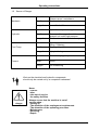
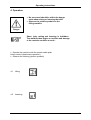
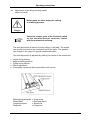
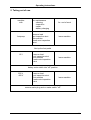
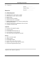
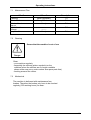
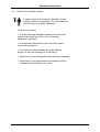
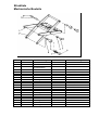
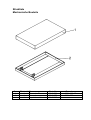
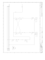
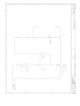
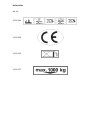
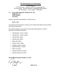
Operating Instructions
ELS 1-10-5
Serial-N°:
70774
Date:
2007-07
These operating instructions are a component part of the lifting
machine. They must be made available at all times for the operators
information. The operating instructions are to be delivered on sale of
the machine.
Operating Instructions
Contents
1
1.1
1.2
1.3
1.4
1.5
1.6
1.7
1.8
1.9
1.10
1.11
2
2.1
2.2
2.3
2.4
2.5
2.6
2.7
3
3.1
3.2
4
4.1
4.2
4.3
4.4
09.2004
SAFETY ...............................................................................................................1
SAFETY HINTS IN THESE INSTRUCTION ..................................................................1
DANGERS OF THIS MACHINE..................................................................................1
REGULATORY APPLICATION ..................................................................................2
DANGER THROUGH ACCESSORIES .........................................................................2
EMISSIONS..........................................................................................................2
SOURCE OF DANGER ...........................................................................................3
QUALIFIED OPERATORS .......................................................................................4
PERSONAL SAFETY EQUIPMENT............................................................................4
SAFETY MEASURES IN THE WORK PLACE ..............................................................4
CONDUCT IN AN EMERGENCY...............................................................................4
PICTURE SYMBOLS ..............................................................................................5
SAFETY FACILITIES...........................................................................................6
INSPECTION SUPPORT. ........................................................................................6
APERTURE RESTRICTION IN CYLINDER INLET...........................................................6
LOWERING BRAKE VALVE (WHEN ON HAND) ...........................................................6
ONE WAY FLOW RESTRICTION VALVE (WHEN ON HAND) .........................................6
FOLDING SCREEN (WHEN ON HAND) ......................................................................6
SECURING DEVICE ON WHEELS (TRANSPORTABLE MACHINES ONLY)........................6
CONTACT FRAME (WHEN ON HAND).......................................................................6
TAKING INTO USE..............................................................................................7
SETTING UP / ASSEMBLY / CONNECTING UP. .........................................................7
TAKING INTO USE.................................................................................................7
OPERATION ........................................................................................................8
LIFTING ..............................................................................................................8
LOWERING ..........................................................................................................8
ADJUSTING THE LOWERING SPEED ........................................................................9
ADJUSTMENT OF THE LIFTING END-STOP SWITCH (WHEN ON HAND)........................10
5
TAKING OUT OF USE.......................................................................................11
6
INSPECTION. ....................................................................................................12
6.1
6.2
6.3
INSPECTION BEFORE THE FIRST USE ....................................................................12
REGULAR TESTING.............................................................................................12
CHECK LIST ......................................................................................................13
ii
Operating Instructions
7
7.1
7.2
7.3
7.4
7.5
7.6
7.7
7.8
7.9
8
INSPECTION / SERVICE...................................................................................14
MAINTENANCE PLAN ..........................................................................................16
CLEANING .........................................................................................................16
MECHANICAL.....................................................................................................16
MAINTENANCE OF THE HYDRAULICS ....................................................................17
OIL CHANGE INTERVALS.....................................................................................17
CHECKING THE OIL LEVEL. ..................................................................................18
OIL CHANGE .....................................................................................................18
BLEEDING THE HYDRAULIC SYSTEM .....................................................................18
CONTROL OF THE HYDRAULIC HOSES...................................................................19
FAULT FINDING ................................................................................................20
8.1
8.2
8.3
8.4
8.5
ELECTRIC MOTOR DOES NOT RUN........................................................................20
LIFTING MACHINE DOES NOT LIFT.........................................................................20
OIL LOSS ..........................................................................................................20
LIFTING MACHINE DOES NOT REACH MAXIMUM HEIGHT ...........................................21
LIFTING MACHINE WILL NOT (COMPLETELY) LOWER ...............................................21
8.6
8.7
THE CONTACT BOARD DOES NOT STOP THE TABLE SINKING ....................................21
LIFTING MACHINE SINKS STRONGLY BY PLACEMENT OF LOAD .................................22
9
9.1
9.2
9.3
GENERAL..........................................................................................................23
TRANSPORT DAMAGE ........................................................................................23
WARRANTY .......................................................................................................23
ORDERING OF SPARE PARTS ...............................................................................23
10 APPENDIX .........................................................................................................24
DIMENSION SHEET
SPARE PART LIST
HYDRAULIC SCHEMA
ELECTRIC SCHEMA
EC DECLARATION OF CONFORMITY
iii
Operating Instructions
1 Safety
1.1 Safety Hints in these Instruction
Draws attention to the fact that
disregard for these instructions could
lead to serious or even deadly
consequences.
Danger
Draws attention to the fact that disregard
of these instructions could under certain
circumstances lead to injuries.
Caution
Indicates that disregard of these instructions could
lead to the damage of the machine or goods on the
machine.
Work that is indicated by this symbol must be
carried out by a competent tradesman (electrician or
industry fitter).
1.2 Dangers of this machine
This machine is equipped with safety devices and is
put through safety and quality control tests but there
is a threat of danger by incorrect operation and
misuse
- for the operator or other people in the vicinity
- for the machine and goods
The danger zone is contained within the outer limits
of the machine.
All personnel concerned with the
- Installation
- Setting Up
- Operation
- Maintenance
- Repair
of the machine must have read and fully understood
the operating instructions.
1
Operating Instructions
1.3 Regulatory Application
Applications
• Lifting of weights until maximum load.
• Working on the raised platform
• Hand Forklifts - Transporting of loads in the
lowered position.
Prohibited
• Lifting and transportation of personnel
(with the exception of lifting tables intended for this purpose on the basis of certain
preparations and safety provisions)
• Setting up and operation of machines in the open.
Exception - machines specially constructed for this purpose
• Alterations and rebuilds of the machine.
Positioning of the load
• Load should not overhang the platform
• Unintentional shifting of the load should be prevented
1.4 Danger through accessories
When the following - Rollers
- Conveyer Belts
- other transport facilities
are used the safety devices on the machine must not be
made in operational through their use.
The danger zone is enlarged through the use of
accessories
1.5 Emissions
See dimension sheet in appendix.
2
Operating Instructions
1.6 Source of Danger
Where?
Mechanic
Hydraulic
What?
Scissors arms
Scissors arms / underframe
Crush and shear points
Danger!
Loss of limbs /life
Where?
Hydraulic components e.g. hoses
What?
Because of damage oil could be
sprayed out under high pressure
Burns and contamination to the eyes
Danger!
Where?
Foot Pump
Current
What?
Operating pedals ,
Lifting / Lowering
Slipping off pedal
Danger!
Injury to the leg
Where?
Current carrying components
What?
Touch
Danger!
Life threatening
Work on the electrical and hydraulic components
should only be carried out by a competent tradesman!
Never
- remove
- alter
- take out of service
the safety facilities
danger
Always secure that the machine is out of
service when - Setting up
- The alteration of the employment requirements
- The alteration of the operating procedure
- Maintenance
- Servicing
- Repair
3
Operating Instructions
1.7 Qualified Operators
The operator must
- be over 18 years old
- be instructed in the operation of the machine
- have proved to the firm that he is capable of
operating the machine
- have clear and written instructions from the firm to
operate the machine
- have read and understood the operating instructions
- must observe the operating instructions
1.8 Personal Safety Equipment
For the operating of the machine
• Safety shoes
For cleaning / maintenance / repair
• Safety shoes
• Work gloves
• Face protection
1.9 Safety Measures in the Work Place
• Secure positioning of the machine
• Avoid crush and shear zones between the machine and
it's surroundings
• Ensure that the workplace remains clean and clear of
obstacles
1.10 Conduct In An Emergency
Footpump
E - Hydraulic
Release the pump /
lower pedal
immediately
Release the raise / lower
push-button immediately
Switch of at the mains /
remove the plug
Secure against further
By raised load support the load carrying component
4
Operating Instructions
1.11 Picture Symbols
Safety and Operational hints on the Lifting Table
1
2
3
4
5
1
Prohibited: Stepping on / Lifting of personnel!
(with the exception of lifting tables intended for this purpose on the basis of certain
preparations and safety provisions)
2
Accumulation of weight forbidden!
3
Prohibited: Staying / Grasping under an unsecured table!
4
Load must be evenly distributed (surface load)!
5
Lower the table onto the inspection support when carrying
out repair and maintenance work alone!
6
You will find the maximum permissible load at the appendix of these instruction.
5
Operating Instructions
2 Safety Facilities.
2.1 Inspection Support.
The unloaded machine should be lowered onto the
inspection support before all repair and maintenance
work! (see section 7)
2.2 Aperture restriction in cylinder inlet
Restricts the oil flow by the rupture of a hydraulic hose
2.3 Lowering Brake Valve (when on hand)
Fixed adjusted limitation of the oil flow (lowering speed)
2.4 One Way Flow Restriction Valve (when on hand)
Adjustable restriction of the oil flow (lowering speed)
Attention : adjustment is dependent on load !
2.5 Folding Screen (when on hand)
Prevents grasping under the raised table.
2.6 Securing Device On Wheels (transportable machines only)
The securing device (brake) prevents the
unintentional movement of the machine.
2.7 Contact Frame (when on hand)
The contact frame stops the lowering of the table when
it comes in contact with an obstacle. Raise the table
with the "raise" button and remove the obstacle then
complete the lowering process
6
Operating Instructions
3 Taking into use.
For technical details see dimension sheet in appendix
3.1 Setting up / Assembly / Connecting Up.
(230 V / 400 V)
During intallation of the lifting table, it is important that the
base frame (when on hand) in the area of the fixed bearings
and the runner wheels is adequately supported with
appropriate packing plates.
Danger
Failure to comply with this instruction will result in loss of
machine-warranty!
• Before taking into use it will be necessary to remove the crane parts (when
onhand), which tighten the under frame together with the top frame.
• Position the machine on a firm level underground
• The machine should be adjusted so that it is level
• Bolt the machine onto the concrete floor
• When the machine is to be connected into the factory ring main,
- connect in a lockable mains switch to prevent
unauthorised use
- This should only be performed by an electrician
Danger
•
• Danger of stumbling because of cable.
• Damage to cable, e.g. because of falling
objects (tools etc.)
• It is forbidden to wind the cables around
mechanical components
Every feed wire must
be secured by 16 A.
Have you read the operating instructions and above
all the safety points and above all understood them?
Then you can take the machine into use
3.2 Taking into use.
• Produce the electrical connection (put the plug in)
• Check the motor rotation (by three phase 400V)
- Control by use of the red arrow on the motor casing
- when incorrect alter by changing the phases in the
plug (electrician only)
• Now you can take the machine into use.
An adequate and safe connection of the earth cable to the workpiece
must be guaranteed when using a lifting table as a welding station.
7
Operating Instructions
4 Operation
• No personnel should be within the danger
zone when raising or lowering the table
• Observe the picture symbols on the
lifting machine
Danger
Short, jerky raising and lowering is forbidden .
The machine then begins to oscillate and damage
to the machine could be a result .
• Operate the machine with the remote cable push
button control (dead mans operation)
• Observe the lettering (picture symbols)
4.1 Lifting
4.2 Lowering
8
Operating Instructions
4.3 Adjusting the lowering speed
(when on hand)
Never grasp the table during the raising
or lowering process.
Danger
The lowering speed of the lifting device must not exceed 150
mm/s.
The recommended lowering speed is 50 mm/s.
Note: It is not possible to use the maximum lowering speed
allowed with some units due to their design.
An adjustment of the lowering speed should not be necessary
(adjusted at works). Should an adjustment be necessary e.g.
through replacement of the flow control valve, then the following
should be observed.
The one-way flow control valve can be found on the pressure
outlet of the hydraulic pump.
• raise load
• loosen securing screw
• adjust valve as required
securing screw
•
•
•
•
tighten the securing screw
lower the load
measure the lowering rate with a stopwatch
if necessary repeat the above procedure
9
Operating Instructions
4.4 Adjustment of the lifting end-stop switch
(when on hand)
Never grasp the table during the raising
or lowering process.
Danger
Select the contact point of the electrical switch
so, that the roller does not come into contact
with the mechanical end-stop.
The end-stop switch is there to limit the lifting of the table. The switch
can usually be found on the fixed pivot end of the table. This position
can change in the case of a special construction table.
The end-stop switch is adjusted by shifting it's position in the slotted rail.
•
•
•
•
•
Loosen fixing screws
Adjust switching position
Tighten fixing screws
Check adjustment
If necessary repeat the above procedure until correct.
Befestigungsschraube
Endschalter
Langlochschiene
Festpunkt
= fixing screw
= End-stop switch
= Slotted rail
= Fixed pivot
10
Operating Instructions
5 Taking out of use.
machine
with
footpump
for: maintenance
-cleaning
-inspection
-repair
-battery charging
-remove load
-put inspection strut
into position
-lower onto inspection
strut
for: end of work
lower machine
fold up the foot pedal
12 V
- remove load
- put inspection strut
into position
- lower onto inspection
strut
lower machine
battery main switch into "off" position
230 V
400 V
- remove load
- put inspection strut
into position
- lower onto inspection
strut
lower machine
remove mains plug and or mains switch "off"
11
Operating Instructions
6 Inspection.
6.1 Inspection before the first use
The machine is tested by the manufacturer before
delivery
Machines that are delivered not ready for use should
be inspected by a qualified person in the following
aspects ;
- correct construction
- correctness for use
6.2 Regular testing
Regular testing of machines at intervals of at the
longest one year should be carried out by a qualified
person.
• use the check list on the following page
• make a photo copy of the list
• note top right on the check list
- Lfd N° (check list number)
- machine type
- serial number
• cross each point when it is in order
• put the machine back into use only when each point
has been crossed
• when completed put the check list into the appendix
of these operating instructions
12
Operating Instructions
6.3 Check List
Lfd.-Nr°: .......................
Machine Type: ........................
Mechanical
O
O
O
O
O
O
O
O
Serial-N.°: ........................
Cylinder pins secure
All lever pins secure
Inspection strut in order (when on hand)
Wheel brakes in order (when on hand)
Machine clean
Stickers intact and readable
Welded construction undamaged
Machine holds the load in the maximum raised position
for at least 10 minutes
O Protective folding screen undamaged (when on hand)
O All bolted connections tight
Hydraulic
O
O
O
O
O
No leaks in the hydraulic system
Oil level correct
No damage to the hoses (see 7.5)
Lowering speed correctly adjusted
Flow control valve secured (when on hand)
Electric
O
O
O
O
Cable connections tight
Cables secured
No damage to cables
Contact rail in order (when on hand)
O Battery is clean and in order (when on hand)
O All functions inspected without query
Inspection date, Inspector (signature)
13
Operating Instructions
7 Inspection / Service
Work should only be carried out on the lifting table when it is
unloaded and the issued inspection strut is in it’s designated
position.
The inspection strut can be found on or near the under frame.
Danger
Operation:
•
The unloaded scissor lift should be fully raised
•
position the strut in the lower pocket.
•
hold the strut in a vertical position and lower the scissor lift.
Ensuring that the strut is in it’s correct position!
Should it not be possible to raise the scissor lift using it’s own drive, then the platform
should be raised using some suitable means (hydraulic jack or crane). The platform
should be raised from the fixed pivot end.
It should be noted that a vacuum is produced in the cylinders when the scissor
lift is raised using an external method and that they do not support the scissor
lift hydraulically (on a column of oil).
The scissor lift should be raised from the inspection strut using it’s own hydraulic drive
(or an external hydraulic drive) when service work is completed to ensure that the
cylinders support the weight of the scissor lift.
LIFE THREATENING DANGER
The inspection struts should never be removed (by hammer blow or
cutting) before the lifting table has been raised from the service
position using it’s hydraulic drive. An uncontrolled lowering of the
scissor lift and platform could be the result.
Danger
The inspection strut can be removed:
•
by first raising the scissor lift a short distance.
•
then remove the strut and return it to it’s stowed position.
The operator should under no circumstances be positioned within the lifting table when
performing this task.
14
Operating Instructions
Possible methods of using the inspection strut
Dia. 1: Inspection strut between upper and lower frame.
Dia. 2: Inspection strut between scissor arms.
Abb. 3: Inspection strut between roller and frame.
15
Operating Instructions
7.1 Maintenance Plan
What?
When?
Description
Cleaning
When necessary
7.2
Check Bushes
Every 250 hours
7.3
Yearly
7.6
Check oil level
top up
Hydraulic oil
change
Inspect oil hoses
7.7
-------Yearly
7.9
7.2 Cleaning
Secure that the machine is out of use
Danger
Clean
- your machine regularly
- especially the stickers (picture symbols) on the
machine.(when the stickers are no longer readable
please order new ones, order number see spare parts lists)
- working areas of the rollers
7.3 Mechanical
The machine is delivered with maintenance free
bushes. Therefore the bushes only have to be checked
regularly (250 working hours) for wear.
16
Operating Instructions
7.4 Maintenance of the hydraulics
Hydraulic oil can cause irritation and skin
rashes. Avoid prolonged skin contact and
wash the skin thoroughly after contact.
Danger
Wear protective clothing!
(see chapter 1.8)
Protect the environment:
The handling and disposal of mineral oils is covered
by laws. Dispose of old oil at an authorised disposal
unit. Information can be found from the responsible
authority. Be careful not to spill any hydraulic oil.
Make precautions to catch any spilt oil
(oil resistant covers, drip tray etc.)
This machine is filled with
bio-oil on synthetic base
This oil is not mixable with water.
The biological removable hydraulic-oil
is mixable with mineral-oil, but then it
will loosen his biological removability.
The following or equivalent can be used
Total Biohydran TMP 46
BP
Biohyd SE 46
Fuchs Plantohyd 46S
Esso Hydraulicoil HE 46
Total Equivis UVS 46
Shell Naturell HF-E 46
→ in this machine
7.5 Oil Change Intervals
The oil must be changed after the first 50 working
hours, thereafter at intervals of 500 hours or at the
latest every 2 years
17
Operating Instructions
7.6 Checking the oil level.
•
•
•
•
Raise the table into its uppermost position.
Read the position in the oil gauge pipe
The level must be at least in the lower quarter of the pipe
When necessary top-up the oil
Breather bung
Tank
Oil gauge pipe
7.7 Oil Change
• Lower the table without load onto its inspection strut.
• Position a drip tray under the hydraulic cylinder
• Loosen the hose on the cylinder and lay into the
drip tray
• Operate the pump (raise) until no more oil is
discharged from the hose
• Reconnect the hose
• Remove the breather bung from the tank
• Fill up with oil
• For volumes see dimension sheet in appendix
• Replace the breather bung
• Bleed the hydraulic system
7.8 Bleeding the hydraulic system
• Lower the table without a load onto the
inspection strut.
• Loosen the bleed screws on the cylinder one or
two turns.
• When no bleed screws are on hand the cylinders
are so constructed as to bleed themselves.
• Operate the pump (raise) until oil is discharged
from the bleed screws without air bubbles.
• Check the oil level.
• Top up when necessary.
18
Operating Instructions
7.9 Control of the hydraulic hoses
A yearly check on the hydraulic hoses for a safe
working condition is stipulated. The check must be
carried out by a qualified tradesman.
Control the following
• Can the following damage be observed on the outer
mantel of the hose rips, kinks, cuts, unbending,
abrasions or splitting?
• Are there any deformities in the hose when under
or not under pressure?
• Are there any leaks between the hoses and the
fittings? Is the hose coming out of the fitting?
• When there is any damage the hose should be changed.
• Depending on the requirements the hoses should be
changed at the latest after six years.
19
Operating Instructions
8 Fault Finding
Work on the electrical and
hydraulic components should
only be carried out by a
competent tradesman!
Danger
Observe the safety instructions
8.1 Electric motor does not run
Cause
Cure
Current supply broken
Check:
• Feed line
• Fuse
• Circuit breaker
Motor is faulty
Exchange hydraulic pump
8.2 Lifting machine does not lift
Cause
Cure
Table is overloaded
Reduce load
Motor is faulty
Exchange hydraulic pump
Leaks in the hydraulic system
See 8.3
Pump does not produce pressure
Exchange hydraulic pump
Motor rotates in the wrong direction
Check the motor rotation
(by three phase 400V)
- Control by use of the red arrow
on the motor casing
- when incorrect alter by changing the
phases in the plug (electrician only)
8.3 Oil loss
Cause
Cure
Leaks in the hydraulic system
•
•
•
•
re-tighten fittings
replace cylinder seals
exchange cylinder
exchange hoses
20
Operating Instructions
8.4 Lifting machine does not reach maximum height
Cause
Cure
Oil level too low (see point 8.3)
• top-up oil
8.5 Lifting machine will not (completely) lower
Cause
Cure
Machine is blocked by inspection strut
Raise table and remove
inspection strut
Obstructions (dirt) in the rollers
working surfaces
Clean working surfaces
Contact board has been activated
by an obstacle
Raise table, remove
obstacle and test the
function of the contact board
Contact board switch is defect
Exchange switch
Magnet lowering valve defect
Exchange valve
The neutral is incorrectly or not
connected (only 230 V / 400 V)
Check feed
8.6 The contact board does not stop the table sinking
Cause
Cure
Contact board is defect (e.g. bent)
Exchange contact board
The fixing screws of the contact
board switch are loose
re-tighten screws
and align contact board switch
Contact board switch is defect
Exchange switch
Contact board switch cable is defect
Replace cable
21
Operating Instructions
8.7 Lifting machine sinks strongly by placement of load
Cause
Cure
Air in hydraulic system
• Bleed hydraulic system
• Drive table repeatedly
(2-3 sec) against the
mechanical end-stop
Hydraulic feed hose too long
(only tables whose pump is
outside the table)
• Hoses of more than 3m
from table to pump
should be avoided
22
Operating Instructions
9 General
9.1 Transport Damage
All deliveries are to be insured by the customer.
We must turn down any possible claims
concerning
transport
responsibility.
Our
responsibility is restricted to the hand - over of
the machine in brand-new condition to the
shipping agent. Should you discover any damage
to the machine, do not use it and contact the
shipping agent concerning the damage.
9.2 Warranty
Every machine is covered by a 12 months
warranty against material faults and incorrect
assembly. The warranty covers all parts that are
returned post free within twelve months for
inspection. The parts will then be inspected by us
to determine whether the parts were damaged
under normal use. The warranty will be declared
void if the parts are found to have been
overloaded,
handled
incorrectly
or
that
replacement parts have been assembled
incorrectly.
9.3 Ordering of spare parts
Please give the following details when ordering;
Type:
Load:
Year of construction:
Serial Number:
Part description:
Order Number:
The address for ordering is to be found on the cover
of this operating instructions.
23
Operating Instructions
10 Appendix
24
Technische Daten (Technical ratings)
ELS 1-10-5
Mechanik / Mechanics
Traglast (maxload): ................................................................. 1000 kg
Belastungsart (nature of load):................................................ Flächenlast / surface load
Bauhöhe (building height): ...................................................... 200 mm
Nutzhub (effective stroke): ...................................................... 1000 mm
Tischplatte Maße (platform): ................................................... 5 x 1500 x 800 mm
Glattblech / plain sheet
Unterrahmen (bottom frame):.................................................. 1500 x 750 mm
Hubzeit belastet (lifting time, loaded): ..................................... ca. 13 sec.
Senkzeit belastet (sinking time, loaded):................................. ca. 12 sec.
Gewicht (weight):..................................................................... ca. 290 kg
Elektrik / Electric
Leistung Hydraulikaggregat (power): ...................................... 2,3 kW
Stromaufnahme (current consumption): ................................. 5,5 A
Schutzart (enclosure): .............................................................IP 55
Betriebsspannung (operating voltage): ................................... 400 V
Steuerspannung (control voltage): .......................................... 230 V
Steuerung (control system): .................................................... Totmann, Handtaster (3m)
Deadman, hand switch (3m)
Hydraulik / Hydraulic
Betriebsdruck (working pressure): .......................................... max. 180 bar
Anordnung Aggregat (positioning of drive unit):...................... innerhalb / inside
Ölfüllmenge (oil filling): ............................................................ 2 l
Ölsorte (kind of hydraulic oil):.................................................. Bioöl / biooil
Hydraulikzylinder (hydraulic cylinder):..................................... 1 x Ø 80 x 250 mm Hub / stroke
Stückliste
Mechanische Bauteile
Pos.
1
2
3
Stückzahl
1
1
8
5
4
4
5
5
5
5
6
6a
6b
7
8
9
13
14
14
14
14
14
4
2
2
1
2
2
2
4
4
4
8
4
8
2
1
1
1
1
1
Benennung
Schere, außen
Schere, innen
Fest- und
Laufrollenbolzen
Passscheibe
Buchse
Buchse
Scherenachse
Scheibe
Federring
6kt.-Schraube
Laufrolle mont.
Laufrolle
Buchse
Scheibe
Buchse
Sicherungsmutter
Buchse
Zylinderbolzen
6kt.-Schraube
Federring
6kt.-Schraube
Sicherungsmutter
Best.-Nr.
50.11.272
50.11.222
10.16.160
Bemerkung
10.40.510
10.02.294
10.02.283
55.57.231
12.40.137
12.40.440
12.53.041
42.99.474
12.09.690
10.02.287
12.40.136
10.02.287
12.55.109
10.02.294
50.82.064
12.51.081
12.40.425
12.50.281
12.55.042
DIN 988-35x45x1
GSM 40440-30
GFM 4044-40 mit Bund
DIN 668-S235JRG2K-40x621
ISO 7094-16-100HV
DIN 128-A16-FSt
ISO 4017-M16x35-8.8
Ø 45 x 70
Ø 70 x 20
GSM 3539-20
17 DIN 7349-St
GSM 3539-20
DIN 985-M16-10
GSM 4044-30
Ø 40 x 110
ISO 4017-M10x30-8.8
DIN 128-A10-FSt
ISO 4014-M8x80-8.8
DIN 985-M8-8
Stückliste
Mechanische Bauteile
Pos.
1
2
Stückzahl
1
1
1
Benennung
Oberrahmen
Unterrahmen
Inspektionsstütze
Best.-Nr.
50.02.556
50.02.375
56.67.295
Bemerkung
1500 x 800 mm
1500 x 750 mm
Kontaktleiste
Art.-Nr.
12.55.038 (L=25 mm)
12.55.039 (L=40 mm)
12.23.028
12.15.539
12.16.521
12.23.503
10.28.084
19.27.661
Stückliste
Hydraulische Bauteile
Pos.
1
2
3
4
5
5a
Stückzahl
Benennung
1
Hydraulikaggregat
1
Senkbremsventil
1
2/2-Wegemagnetventil
1
Leitungsbruchsicherung
1
Hydraulikzylinder
1
Dichtungssatz für
Zylinder
Best.-Nr.
11.19.386
12.19.436
10.19.463
10.19.292
Bemerkung
2,3kW/400V/50Hz
8,5 l/min
SV 98-2006
230 V AC
3/8“
11.19.084
50.97.091
Ø 80 x 250 mm Hub
Ø 80 mm
Hydraulikbauteile
Stück
1
Art.-Nr.
10.19.103
L = mm
1050
DN
8
A
M 16x1,5-SW 19
B
M 16x1,5-SW 19
Einstellbare T-Verschraubung
Stück Art.-Nr. Baureihe
1
12.19.240
L
DN
8
A
M 16x1,5
B
M 16x1,5
DN
8
8
A
1/4”
M 14x1,5
B
M 16x1,5
M 16x1,5
DN
8
8
A
1/4”
3/8”
B
M 16x1,5
M 16x1,5
DN
8
A
3/8”
B
M 16x1,5
DN
8
A
M 16x1,5
Gerade Einschraub-Verschraubung
Stück Art.-Nr. Baureihe
1
12.19.265
L
1
12.19.267
L
Gerader Einschraubstutzen
Stück Art.-Nr. Baureihe
1
12.19.235
L
1
12.19.258
L
Winkel-Schwenkverschraubung
Stück Art.-Nr. Baureihe
2
12.19.261
L
Steckkupplung (Messanschluss)
Stück Art.-Nr. Baureihe
1
12.19.434
L
Magnetventil
Stück
1
Art.-Nr.
10.19.463
A
1/4“
B
1/4“
Bemerkung
SV98-2006 / 230V, 19 W, 0,1 A
Senkbremsventil
Stück Art.-Nr.
1
12.19.436
A
3/8”
B
3/8”
Bemerkung
8,5 l/min
Stück Art.-Nr.
1
10.19.292
A
3/8”
Spaltmaß
Bemerkung
Leitungsbruchsicherung
Haftschilder
Art.-Nr.
10.33.334
10.33.358
10.33.242
10.33.237
EC Declaration of Conformity
Conforming to:
EC-Directives – Machines 98/37/EG, appendix II A
EC-Directives – Electromagnetic compatibility 89/336/EWG,
EC-Directives – „Low voltage“ 73/23/EWG
We:
Gruse Maschinenbau GmbH & Co. KG
Dibbetweg 32
31855 Aerzen
Germany
declare in general responsibility, that the product
ELS 1-10-5,
convered by this declaration confirms to the Health and Safety rules laid down
by the directives above.
The following Norms were used for the proper implemention of the EC
Directives on Health and Safety:
•
DIN EN ISO 12100-1 (2003)
•
DIN EN ISO 12100-2 (2003)
•
DIN EN 294 (1992)
•
DIN EN 349 (1993)
•
BGR 500 (2004)
•
DIN EN 1570 (1998)
•
DIN EN 1570/A1 (2004)
•
DIN EN 60204-1 (1997)
•
BGV A3 (1997)
•
DIN EN 61000-6-2 (2001)
•
DIN EN 61000-6-4 (2001)
Gruse Maschinenbau GmbH & Co. KG
F. Kraft
2007-10-19