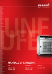
1
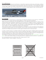
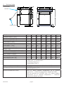
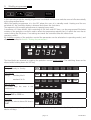
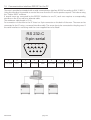
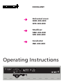
EXCELLENT
Universal oven
UNE 200-800
UFE 400-800
Steriliser
SNE 200-400
SFE 400-800
Incubator
INE 200-800
Operating Instructions
Mo
Tu
We
Th
Fr
Sa
t3
Su
on
off
4
t4
t2
h
3
t1
loop
STERI
IN 1
DEFRO
°C
°C
2
1
PRINT
set
SETUP
on
off
MAX
MIN
AUTO
IN 2
OUT
%rh
mb
IN 1
IN 2
OUT
CO2
mb
EXCELLENT
page 2
1.
2.
2.1
2.2
2.3
2.4
3.
3.1
3.2
3.3
3.4
4.
4.1
4.2
4.3
5.
5.1
5.2
5.3
5.4
5.5
6.
7.
8.
9.
10.
11.
11.1
12.
12.1
12.2
13.
14.
15.
15.1
16.
16.1
16.2
17.
18.
19.
20.
21.
22.
23.
Contents ................................................................................................................................... 2
General notes and safety notes .................................................................................................4
Intended purpose when used as medical product ...................................................................... 4
Transport .................................................................................................................................. 4
Initital start-up ..........................................................................................................................5
Oven load .................................................................................................................................. 5
Technical data ............................................................................................................................6
Standard equipment of EXCELLENT ovens ..................................................................................7
Material quality ..........................................................................................................................7
Electrical equipment ...................................................................................................................8
External connection ...................................................................................................................8
Installation facilities (accessories) ................................................................................................9
Subframe ................................................................................................................................... 9
Wall bracket ............................................................................................................................... 9
Stackable version .......................................................................................................................9
Oven construction and operation .............................................................................................10
Operating the door ..................................................................................................................10
Controls and indications ...........................................................................................................11
Switching on ...........................................................................................................................11
Setting air changes ..................................................................................................................11
Setting the temperature ...........................................................................................................11
Selecting the operating mode ..................................................................................................12
Setting the parameters .............................................................................................................12
Normal operation
..............................................................................................................13
Weekly programmer
..........................................................................................................15
Ramp timer
.......................................................................................................................17
Basic oven settings SETUP ...........................................................................................................23
Real-time clock ......................................................................................................................... 23
Temperature monitor and protection devices ............................................................................24
Mechanical temperature monitor: temperature limiter (TB) ....................................................... 24
Electronic temperature monitor ................................................................................................24
Calibration ............................................................................................................................... 26
Communication interface RS232C for the PC ............................................................................28
Report memory ........................................................................................................................29
Reading the report memory into the PC via RS232C .................................................................. 29
Sterilisers ................................................................................................................................ 30
Guidelines for sterilisation in MEMMERT hot air sterilisers ......................................................... 30
Steriliser cassettes ....................................................................................................................34
Cleaning .................................................................................................................................. 35
Maintenance ............................................................................................................................35
Error messages .........................................................................................................................36
Supply failure ...........................................................................................................................36
CE Conformity Declaration .......................................................................................................37
Address ................................................................................................................................... 40
Index ....................................................................................................................................... 41
1. Contents
page 3
EXCELLENT
2.
General notes and safety notes
You have purchased a technically fully proven product which has been produced in Germany with the use
of high-grade materials and the application of the latest manufacturing techniques; it has been factory
tested for many hours.
In addition we guarantee the supply of spare parts over 10 years.
This mark in the Operating Instructions means:
Watch out
Important Note
This mark on the product means:
Note Operating Instructions
Warning – oven hot when operating
Observation of the Operating Instructions is necessary for faultless
operation and for any possible claims under warranty. If these
Instructions are disregarded, all claims under warranty, guarantee and
indemnification are excluded.
The right to technical modifications is reserved.
Dimensional details are not binding.
2.1 Intended purpose when used as medical product
For ovens covered by the scope of the Directive 93/42/EWG (Directive of the Commission on the
harmonization of the legal regulations of the Member States on medical devices) the following intended
purpose applies:
For ovens series INE / UNE / UFE:
The product is intended for heating non-sterile cloths, sheets and blankets.
For ovens series SNE / SFE:
The product is intended for the sterilisation of medical products with dry heat using hot air at atmospheric
pressure.
2.2 Transport
Always use gloves!
If the oven has to be carried, at least 2 persons are required to transport it.
EXCELLENT
page 4
2.3 Initital start-up
When the oven is started up for the first time, it should be supervised continuously until steady conditions
have been reached. Severe vibrations during transport may cause movement of the temperature probes
in their holder inside the chamber. Note therefore that before the first start-up the temperature probes
should be checked for their correct position and, if necessary, carefully aligned in their mounting (see ill).
Ill: Chamber ceiling with Pt 100 metal temperature probes
2.4 Oven load
Full consideration must be given to the physical and chemical properties of your load (e.g. combustion
temperature etc.) in order to prevent serious damage to load, oven and surroundings.
Please note that the Memmert ovens described here are not explosionproof (they do not conform to the
Industrial Association Specification VBG 24) and are therefore not suitable for drying, evaporating and
burning-in of paints, enamels or similar materials whose solvents may produce an inflammable mixture
with air. There must be no possibility of the formation of inflammable gas/air mixtures either within the
oven chamber or in the immediate surroundings of the equipment.
Large amounts of dust or corrosive fumes inside the oven chamber or in the surroundings of the equipment
may produce deposits within the oven and lead to short-circuits or damage the electronics. It is therefore
important that adequate precautions are taken against excessive dust or corrosive fumes.
In order to ensure proper air circulation inside the chamber, there must be sufficient spacing of the load
inside the oven. Do not place any load on the floor, against the side walls or underneath the ceiling of the
chamber (heating ribs). In order to ensure optimum air circulation the shelves must be so inserted that the
air spacings between door, shelf and rear chamber wall are approximately equal.
The maximum number and the loading of the shelves can be found in the table in the Section “Technical
Data“. With unfavourable loading (too closely spaced) and completely opened ventilation it is possible that
the set temperature may be reached only after a longer period of time.
See stick-on label “Correct Loading“ on the oven!
page 5
EXCELLENT
3.
Technical data
connection
RS232C
supply plug
Model
Chamber width A [mm]
Chamber height B [mm]
Chamber depth C [mm]
Oven width D [mm]
Oven height E [mm]
Oven depth F [mm]
Chamber volume [Liter]
Weight [kg]
Power, ovens UNE/UFE/SNE/SFE [W]
Power, ovens INE [W]
Max. number of shelves
Max. load per shelf [kg]
Total load per oven [kg]
Ambient conditions
Setpoint temperature range
Setting accuracy:
Working temperature range
EXCELLENT
200
300
400
500
600
700
800
400
480
400
560
800
1040
1040
320
320
400
480
640
800
1200
250
250
330
400
500
500
600
550
630
550
710
950
1190
1190
600
600
680
760
920
1080
1605
400
400
480
550
650
650
750
32
39
53
108
256
416
749
28
30
35
50
87
121
170
1100
1200
1400
2000
2400
4000
4800
440
500
800
900
1600
1800
2000
3
3
4
5
7
8
10
15
12
30
30
30
30
30
30
30
90
60
80
100
160
Ambient temperature 5°C to 40°C
rH 80% max., no condensation
Overvoltage category: II
Contamination level: 2
20°C to nominal temperature (details see label)
INE: 0.1°C
UNE/UFE/SNE/SFE: 0.5°C
From 5°C above ambient temperature up to nominal
temperature = maximum temperature (details see label)
With fan switched on (UFE/SFE) from 10°C above ambient
temperature up to nominal temperature = maximum
temperature (details see label)
page 6
3.1 Standard equipment of EXCELLENT ovens
•
Electronic fuzzy-suported PID process controller with delayed programme start, programmable
heating and cooling ramp, setpoint-dependent waiting time and repeat function loop .
The controller has permanent power matching and an auto-diagnostic system for rapid fault
finding (see Section: “Error messages“)
•
Internal report memory 1024kB for storing actual temperature, setpoint temperature and error
states with time stamp
•
Fan with speed adjustment on recirculation ovens (adjustment in 10% steps)
•
Manually adjustable air valve for recirculation or fresh air operation
•
Integral weekly programmer with group function (e.g. all workdays)
•
Recessing push/turn control for simple operation of oven
•
Visual alarm indication
•
Digital overtemperature monitor (TWW Class 3.1)
•
Mechanical temperature limiter (TB Class 1)
•
Monitor relay to switch off heating in case of fault
•
Two separate PT100 temperature sensors Class A in 4-wire circuit for control and monitoring
•
Convenient 3-point temperature calibration
•
Temperature-dependent ventilation of control panel and door
•
Serial RS232C interface for computer-supported temperature programmes and for reading
the internal report memory
•
MEMMERT software “Celsius 2005“ for remote operation of oven via a PC
•
Special equipment (to be ordered separately as accessories): adjustable temperature limiter (TWB),
subframe, wall bracket, wire shelf, sterilisation cassette, cable RS232C to DIN 12 900-1
3.2 Material quality
For external casing and working chamber MEMERT are using stainless steel (Mat.Ref. 1.4301) which features
high strength, optimum hygienic properties and corrosion resistance against many (not all) chemicals
(warning against e.g. chlorine compounds).
The oven load has to be checked carefully for its chemical compatibility with the above materials.
A compatibility table covering all these materials can be requested from MEMMERT.
page 7
EXCELLENT
Do not place the oven on a readily inflammable support surface!
WARNING! Always pull out the supply plug
before opening the oven cover!
3.3 Electrical equipment
•
•
•
•
•
•
•
•
Operating voltage see label 50/60 Hz
Current rating see label
Protection Class 1, i.e. operating isolation with ground connection to EN 61 010
Protection IP20 to EN 60 529
Interference suppression to EN55011 Class B
Oven protected by a fuse 250V/15A fast blow
Controller protected by a 100 mA fuse (200 mA on 115 V)
When connecting a MEMMERT oven to the electrical supply you have to observe any local
regulations which apply (e.g. in Germany DIN VDE 0100 with FI protection circuit)
This product is intended to operate on a supply network with a system impedance Zmax at the
transfer point (building connection) of 0.292 Ohm max. The user has to ensure that the product is
only operated on an electrical supply network which meets these requirements. If necessary, details
of the system impedance can be obtained from the local electricity supply authority.
3.4 External connection
Equipment connected to the external connections must have interfaces which meet the requirements for
safe low voltage (e.g. PC).
EXCELLENT
page 8
Installation facilities (accessories)
The oven can be placed on the floor or on a
bench (working surface). It is important that
the oven is set up accurately horizontally; the
door may have to be adjusted (see Section:
“Maintenance“)
min.
20 cm
4.
8 cm
8 cm
15 cm
min.
min.
min.
The spacing from the back of the oven to the
wall should be at least 15 cm. The spacing to
the ceiling must not be less than 20 cm and
that at the side to the wall not less than 8 cm.
Generally it is essential to have adequate air
ventilation around the oven.
Model 800 is mounted on castors. The front castors pivot and can be locked. In order to ensure the stability
of the oven the front castors must always be set facing towards the front.
Information on accessories will be found in our leaflet or on our internet page
www.memmert.com.
Please note the installation instructions for our accessories.
4.1 Subframe
Oven models 500 to 700 can be mounted on a subframe (accessory)
4.2 Wall bracket
Oven models 200 to 700 can be wall-mounted using the wall bracket (accessory).
The wall bracket is factory-fitted with a fire-resistant plate. The size and length
of the screws used and of the corresponding dowel plugs depend on the total
weight (oven plus load) and vary with the condition of the wall.
4.3 Stackable version
Two ovens of the same model size can be stacked on each other. Note that
the oven with the lower working temperature must always be placed at the
bottom.
Foot locators (accessory) have to be fitted on the bottom oven. (Model 700 can
only be stacked using an intermediate frame.)
•
Take off cover of bottom oven
•
Place drill jig (supplied with foot locators) into the inverted cover at
the back
•
Mark holes and drill 4.2 mm dia.
•
Screw the foot locators to the top of the cover using the screws and
nuts supplied
•
Re-fit the cover
page 9
EXCELLENT
5.
Oven construction and operation
Ovens Series UNE, INE and SNE have natural ventilation.
In Series UFE amd SFE ovens, air circulation is provided by a fan on the back wall of the chamber.
6
air valve
4
chamber
7
air discharge
3
ventilation slots
5
fan
2
preheat chamber
1
air supply
fresh air
The incoming air (1) is warmed in a preheat chamber (2) in both convection and fan-circulation ovens. The
preheated air enters the chamber (4) through ventilation slots (3) in the chamber side wall. The fan (5) on
the chamber back wall produces a larger air throughput and a more intensive horizontal forced circulation
compared with natural convection. The air valve (6) on the back of the oven controls the rate of air intake
and discharge (air change) (7).
close
EXCELLENT
page 10
5.1 Operating the door
The door is opened by pulling on the door handle.
The door is closed by the door handle being pushed in.
open
5.2 Controls and indications
time display
heating
operating mode indication
Tu
Mo
We
Th
Fr
Sa
t3
Su
on
4
t4
t2
off
h
3
t1
loop
alarm indication
temperature display
STERI
IN 1
DEFRO
°C
°C
2
set
SET key
OUT
%rh
mb
IN 2
OUT
CO2
mb
MIN
AUTO
SETUP
on
off
push/turn control
(main switch)
IN 1
MAX
1
PRINT
IN 2
Ill.. : UFE 500
Ill
air slider
fan indication
monitor temperature
indication
5.3 Switching on
The oven is switched on by pressing the push/turn control.
Oven switched off. The push/turn control is pushed
in and protected against damage
Oven switched on and can be operated using the
push/turn control and the SET key.
5.4 Setting air changes
Moving the air slider opens and closes the air valve to control the supply and discharge of air.
Air valve closed
Air valve fully open
5.5 Setting the temperature
Hold down the SET key and set the temperature setpoint with the push/turn control.
After the SET key has been released the display briefly flashes the temperature setpoint. The display then
changes to the actual current temperature and the controller starts to control to the selected temperature
setpoint.
page 11
EXCELLENT
6.
Selecting the operating mode
PRINT
Normal operation
Weekly
programmer
Ramp timer
Programme
operation
SETUP
Basic settings
After holding down the SET key (approx. 3 sec), the current operating mode flashes on the display.
A different operating mode can be selected with the push/turn control while the SET key is being held
down. After the SET key has been released the controller operates in the new operating mode.
7.
Setting the parameters
After an operating mode has been selected, all relevant controller settings are shown simultaneously on
the display.
A parameter (menu item) can be selected by rotating the push/turn control; all other parameters are then
dimmed.
The selected parameter flashes brightly and can now be altered with the push/turn control while holding
down the SET key.
After the SET key has been released the newly set value is stored.
If the push/turn control or the SET key have not been operated for a period of 30 seconds, the controller
automatically returns to the main menu.
EXCELLENT
page 12
8.
Normal operation
PRINT
SETUP
In this operating mode the oven operates continuously. The settings for operating the oven can be selected.
The settings act directly on the operation of the oven.
°C
˚C
MAX
MIN
AUTO
By rotating the push/turn control the following parameters can be selected and can be altered as described
in the Section “Setting the parameters“:
Temperature setpoint
Range: 20°C up to nominal temperature (details see label)
˚C
Fan speed
Range: 0 to 100%
in 10% steps
Temperature monitor
Range: up to 10°C above nominal temperature (details see label).
(see Section: “Temperature monitor“)
°C
MAX
MIN
AUTO
page 13
EXCELLENT
Setting example “Normal operation“
The oven (UFE500) has to heat up to 180°C at a fan speed of 50%. The overtemperature monitor has to
operate at 200°C.
°C
monitor temperature 200°C
180°C
h
1. Select operating mode “Normal operation“
PRINT
After holding down the SET key (approx. 3 sec), the current operating
mode is flashing. Select operating mode I with the push/turn control
while holding down the SET key.
After the SET key has been released the controller is in
operating mode I.
SETUP
2. Select temperature setpoint
Hold down the SET key and use the push/turn control to select the
required temperature setpoint of 180°C. After the SET key has been
released the oven briefly flashes the temperature setpoint. The display
then changes to the actual temperature and the controller starts
to control to the selected temperature setpoint of 180°C. Heating is
indicated by the orange heater symbol.
˚C
3. Select fan speed
Turn the push/turn control clockwise until the fan symbol is flashing.
While holding down the SET key, use the push/turn control to set 50%
fan speed.
4. Select monitor temperature
Turn the push/turn control clockwise until the monitor temperature
display is flashing. Hold down the SET key and use the push/turn control
to set the monitor temperature to 200°C.
°C
MAX
MIN
AUTO
EXCELLENT
page 14
9.
Weekly programmer
PRINT
SETUP
In this operating mode the weekly programmer is activated and the oven switches on and off automatically
at the programmed times.
While the weekly programmer is in the OFF phase the oven is in standby mode. Heating and fan are
switched off, the controller display is dimmed and shows the clock time.
The sequence of the weekly programmer is repeated every week.
A maximum of 9 time blocks, each consisting of ON time and OFF time, can be programmed.Clockwise
rotation of the push/turn control is used to select the temperature setpoint (etc.) to which the oven has to
control during the ON phase. If no settings are made the controller takes the values from
operating mode I.
By clockwise rotation of the push/turn control the parameters can be selected as in operating mode I, and
altered as described in Section “Setting the parameters“.
Mo
Tu
We
Th
Fr
Su
Sa
on
h
off
The time blocks are selected by rotating the push/turn control anticlockwise. The switching times can be
altered while holding down the SET key.
Weekday
Range: Monday to Sunday
Mo
Tu
We
Th
Fr
Sa
Su
Day groups
Range:
workday Mo-Fr
Mo
Tu
We
Th
Fr
Sa
Su
weekend Sa-Su
Mo
Tu
We
Th
Fr
Sa
Su
No ON time: ---On these days the oven is not
switched on
on
ON time
Range: 00:00 to 23:59 hrs.
OFF time
Range: one minute above ON time to
24:00
off
on
h
off
on
h
off
For safety reasons, always check that an ON time has been programmed only during the required time
blocks and days.
page 15
EXCELLENT
Setting example “Weekly programmer“
Su
Sa
Fr
Th
We
Tu
Mo
The oven (UFE500) has to switch on at 07.30 hrs from Mo to Fr (workday group) and switch off at 18.00
hrs. In addition it has to operate on Saturday from 10.00 to 14.00 hrs.
1. Select operating mode “Weekly programmer“
PRINT
After holding down the SET key (approx. 3 sec) the current operating
mode is flashing. Select operating mode “Weekly programmer“ with
the push/turn control while holding down the SET key.
After the SET key has been released the controller is in operating mode
“Weekly programmer“.
2. Switch on at 07.30 hrs Mo-Fr
Turn the push/turn control anticlockwise to select the symbols “Mo-Fr
on“ (workday group).
Hold down the SET key and use the push/turn control to set the switchon time to 7:30.
3. Switch off at 18.00 hrs Mo-Fr
Using the push/turn control select the symbols “Mo-Fr off“ (workday
group).
Hold down the SET key and use the push/turn control to set the switchoff time to 18:00.
4. Switch on at 10.00 hrs Sa
Using the push/turn control select the symbols “Sa on“.
Hold down the SET key and use the push/turn control to set the switchon time to 10:00.
5. Switch off at 14.00 hrs Sa
Using the push/turn control select the symbols “Sa off“.
Hold down the SET key and use the push/turn control to set the switchoff time to 14:00 hrs.
EXCELLENT
page 16
Mo
Tu
We
Th
Fr
SETUP
Su
Sa
on
h
off
Mo
Tu
We
Th
Fr
Su
Sa
on
h
off
Mo
Tu
We
Th
Fr
Su
Sa
on
h
off
Mo
Tu
We
Th
Fr
Su
Sa
on
off
h
10. Ramp timer
PRINT
SETUP
In this operating mode a fixed ramp sequence is programmed. A time period can be input for each ramp
segment, or the appropriate ramp segment can be de-activated by setting “---“.
After the end of the programme the oven switches off the heating and cools down to ambient temperature.
In the case of ovens UFE and SFE the fan runs on for 30 minutes.
setpoint-dependent
waiting time
hold time
heating
time
delayed
programme start
cooling
time
repeat function
t3
t2
t4
t1
loop
Stop
Edit
Start
By turning the push/turn control the following parameters can be selected and can be altered as described
in the Section “Selecting the parameters“:
Tu
Mo
We
Th
Fr
Sa
t3
Su
on
t4
t2
h
off
t1
loop
°C
°C
MAX
PRINT
SETUP
Delayed programme start t1 : switch-on day
Range: Monday to Sunday, workdays Mo-Fr, weekend Sa-Sun, all days Mo-Su or no day. If no day of the
week is selected, the oven starts up immediately after the programme is started.
Mo
Tu
We
Th
Fr
Sa
t3
Su
on
off
t4
t2
h
t1
loop
°C
°C
MAX
PRINT
SETUP
Delayed programme start t1 : switch-on time
Range: 00:00 to 23:59
If no switch-on day has been selected it is not possible to select a switch-on time, and the programme
starts immediately.
page 17
EXCELLENT
Tu
Mo
We
Th
Fr
Sa
t3
Su
on
t4
t2
h
off
t1
°C
loop
°C
MAX
SETUP
PRINT
Heating time = heating up to setpoint temperature
Range:
no heating time off or 1 minute to 999 hours
Tu
Mo
We
Th
Fr
Sa
t3
Su
on
t4
t2
h
off
t2
t1
loop
°C
°C
MAX
SETUP
Setpoint temperature
Range: 20°C to nominal temperature (details see label)
Tu
Mo
We
Th
Fr
Sa
t3
Su
on
t4
t2
h
off
t1
loop
°C
°C
MAX
SETUP
Setpoint-dependent waiting time
The oven starts the hold time t3 only when the selected setpoint temperature has been reached, even if
this exceeds the time selected at t2 (see programming example)
Range: on or off
Tu
Mo
We
Th
Fr
Sa
t3
Su
on
t4
t2
h
off
t1
loop
°C
°C
MAX
PRINT
SETUP
Hold time = maintain setpoint temperature t3
Range: from 1 minute to 999 hours or no hold time ---Mo
Tu
We
Th
Fr
Sa
t3
Su
on
off
t4
t2
h
t1
loop
°C
°C
MAX
PRINT
SETUP
Cooling time = cooling down to ambient temperature t4
Range: from 1 minuten to 999 hours or no cooling time --If no time is selected, the oven cools down naturally to ambient temperature
EXCELLENT
page 18
Mo
Tu
We
Th
Fr
Sa
t3
Su
on
t4
t2
h
off
t1
°C
loop
°C
MAX
SETUP
PRINT
loop Number of ramp repeats
Range:
off = no repeat function
1-99 = number of repeats
cont = continuous repeat function
Mo
Tu
We
Th
Fr
Sa
t3
Su
on
t4
t2
h
off
t1
°C
loop
°C
MAX
MIN
AUTO
SETUP
Fan speed (UFE/SFE only)
Range:
0 – 100% in 10% steps
Mo
Tu
We
Th
Fr
Sa
t3
Su
on
t4
t2
h
off
t1
°C
loop
°C
MAX
MIN
AUTO
SETUP
Monitor temperature MAX
Range: up to 10°C above nominal temperature (details see label).
see Section: “Temperarture monitor“
Mo
Tu
We
Th
Fr
Sa
t3
Su
on
off
4
t4
t2
h
t1
3
loop
2
STERI
DEFRO
°C
1
PRINT
SETUP
°C
MAX
MIN
AUTO
Start the programme
Turn push/turn control clockwise until the stop symbol
is flashing.
Hold down the SET key and with the push/turn control select start anwählen.
page 19
EXCELLENT
Programming possibilities of ramp timer
Different choice of
possibilities:
loop
and delayed programme start
t1 offer the following programming
loop
Mo
Tu
Th
We
Fr
Su
Sa
Daily ramp sequence by group function, loop and
delayed programme start
t1
loop
Mo
Weekly ramp sequence by loop and
delayed programme start
t1
Several ramp sequences on one day by loop without
delayed programme start
loop
Monday
Tuesday
Wednesday
Thursday
Friday
Saturday
Sunday
Monday
Programming example “Ramp timer“
The oven (UFE500) has to heat up as quickly as possible to 180°C on Monday at 08.00 hrs with a fan speed
of 50%. After reaching the setpoint temperature this has to be held for 45 minutes, followed by cooling
down over two hours.
This programme has to be repeated on Tuesday and Wednesday.
loop 1
0:45h
2:
00
h
2:
00
h
2:
We
8:00h
0:45h
Tu
8:00h
Mo
8:00h
0:45h
loop 2
00
h
1. Select operating mode “Ramp timer“
PRINT
After holding down the SET key (approx. 3 sec) the current operating
mode is flashing. Hold down the SET key and select operating mode
“Ramp timer“ using the push/turn control.
After the SET key has been released the controller is in operating mode
“Ramp timer“.
2. Switch-on day for delayed programme start
Using the push/turn control select the ramp segment “t1“.
Hold down the SET key and set the workdays group using the push/turn
control.
3. Select switch-on time for delayed programme start
Hold down the SET key and set the time 08:00 using the push/turn
control.
t1
Mo
Tu
We
Th
t1
h
EXCELLENT
page 20
SETUP
Fr
4. Select heating time t2
Using the push/turn control select the ramp segment “t2“.
Hold down the SET key and using the push/turn control set the time
00:01. (1 minute is sufficient since a setpoint-dependent waiting time
is being set.)
t2
h
5. Select setpoint temperature
Turn push/turn control clockwise until the temperature display is
flashing. Hold down the SET the key and set the required temperature
setpoint of 180°C using the push/turn control.
t3
t2
˚C
6. Select setpoint-dependent waiting time
Using the push/turn control select the symbol for setpoint-dependent
waiting time.
Hold down the SET key and set on using the push/turn control.
After the SET key has been released the function for setpoint-dependent
waiting time is stored. This ensures that, as rapidly as possible and
immediately on reaching the setpoint temperature, the oven holds the
temperature for 45 minutes (as selected above).
7. Select hold time t3
Using the push/turn control select the ramp segment “t3“.
Hold down the SET key and set the time 00:45 using the push/turn
control.
t3
h
8. Select cooling time t4
Using the push/turn control select the ramp segment “t4“.
Hold down the SET key and set the time 02:00 using the push/turn
control.
t4
h
9. Select programme repeats
Using the push/turn control select the loop symbol.
Hold down the SET key and set 2 repeats using the push/turn control.
page 21
loop
EXCELLENT
10. Select fan speed
Turn the push/turn control clockwise until the fan symbol is flashing.
Hold down the SET key and set fan speed 50% using the push/turn
control.
11. Select monitor temperature
Turn the push/turn control clockwise until the monitor temperature
display is flashing. Hold down the SET key and set the monitor
temperature to 200°C using the push/turn control.
°C
MAX
MIN
AUTO
12. Start the programme
Turn the push/turn control clockwise until the stop symbol
is flashing.
Hold down the SET key and select start
using the push/turn control.
On releasing the SET key the programme starts to run.
EXCELLENT
page 22
11. Basic oven settings
SETUP
PRINT
SETUP
In this operating mode it is possible to make the basic settings for the oven. Clock time, date, day, year and
calibration are set here.
The following parameters can be selected by turning the push/turn control, and altered as described in the
Section “Setting the parameters“:
Clock time in 24-hour format
The winter/summer time changeover
does not take place automatically but
must be set manually by the user.
h
Date
The controller incorporates a calendar
which automatically allows for the
different lengths of the months and also
for leap years.
Weekday
Mo
Year
Range: from 2000 to 2100
Calibration temperature and calibration
correction for user-calibration
CAL1 to CAL3
(see Section: “Calibration“)
11.1 Real-time clock
The real-time clock is set in SETUP and includes date and clock time.
The real-time clock serves for reports according to GLP.
Date and clock time are marked in the report memory.
On the graphics print from the PC the time axis is marked in real-time.
The clock runs with a buffer battery independently of the mains power supply.
The built-in lithium battery Type CR 2032 has a life of approx. 10 years.
page 23
EXCELLENT
12. Temperature monitor and protection devices
The monitor temperature is measured with a separate PT100 temperature sensor inside the chamber. The
monitor unit provides protection for the oven load as well as protection for oven and its surroundings.
The oven is provided with duplicate overtemperature protection (mechanical / electronic) according to
DIN 12 880.
visual alarm symbol
alight:
TB alarm
flashing:
TWW alarm
TWB alarm
°C
Monitor temperature
(TWW, TWB)
MAX
MIN
AUTO
12.1 Mechanical temperature monitor: temperature limiter (TB)
All ovens of the EXCELLENT series are equipped with a mechanical temperature limiter (TB) Protection Class
1 to DIN 12 880.
If the electronic monitor system should fail during operation and the fixed factory-set maximum temperature
is exceeded by approx. 20°C the temperature limiter switches off the heating permanently as a final
protective measure. The alarm symbol lights up as warning
1.
2.
3.
4.
Fault rectification after the TB cut-out has been activated:
Switch off the oven and allow it to cool down
Rectify the fault (e.g. replace temperature probe) and where appropriate contact customer service
The oven is again ready for operation only after it has cooled down and after the fault has been
rectified.
12.2 Electronic temperature monitor
Monitor temperature
°C
Range: up to 10°C max above
nominal
temperature
(for
nominal temperature see label)
MAX
Using the push/turn control select the
symbol MAX .
Hold down the SET key and set the protection
temperature using the push/turn control.
MIN
AUTO
Note:
The temperature monitor can be set independently of the operating mode.
During ramp operation the monitor temperature must always be set sufficiently far above the maximum
working temperature.
EXCELLENT
page 24
The manually set monitor temperature MAX of the electronic overtemperature protection system is
monitored, in the case of EXCELLENT ovens, by an adjustable temperature monitor (TWW) Protection Class
3.1 to DIN 12 880, or as an option by an adjustable temperature limiter (TWB) Protection Class 2 to DIN
12 880. For details of temperature monitor system and Protection Class see label.
Adjustable temperature monitor (TWW) Protection Class 3.1 to DIN 12 880
If the manually set monitor temperatur MAX is exceeded, the TWW takes over the control of the temperature
and starts to control at the monitor temperature. As a warning the alarm symbol
is flashing.
°C
TB approx. 20°C above Tmax
220°C
emergency operation
TWW set manually
setpoint temperature
150°C
controller fault
20°C
t
Adjustable temperature limiter (TWB) Protection Class 2 to DIN 12 880 (option)
If the manually set monitor temperatur MAX is exceeded, the TWB switches off the heating permanently
and can only be reset by pressing the SET key. As a warning the alarm signal
is flashing.
°C
TB approx. 20°C above Tmax
220°C
heating switched off by TWB
TWB set manually
setpoint temperature
150°C
controller fault
20°C
t
page 25
EXCELLENT
13. Calibration
User-calibration of oven and controller, with three calibration temperatures selected by the user.
CAL.1 temperature calibration at low temperature
CAL.2 temperature calibration at medium temperature
CAL.3 temperature calibration at high temperature
Either a positive or a negative calibration correction can be applied to each selected calibration point.
General calibration instructions:
1.
2.
3.
4.
5.
Select the required calibration temperature in SETUP and set the corresponding calibration
correction to 0.0°C.
Measure the deviation from the selected calibration temperature under steady conditions, using a
reference instrument.
Set the calibration correction in SETUP. If the measured reference temperature is too low, the
calibration correction setting has to have a positive sign.
Carry out a check measurement using the reference meter.
The procedure can be carried out for up to 3 calibration temperatures.
Example: Correction of a temperature deviation in the load at 100°C.
1.
2.
3.
4.
5.
Set calibration temperature CAL.2 to 100.0°C in SETUP and set the corresponding calibration
correction to 0.0°C.
Using a calibrated reference instrument, an actual temperature of 100.4°C is measured in normal
operation for a setpoint temperature of 100°C.
In SETUP set the calibration correction for CAL.2 to –0.4°C.
After the oven has settled down the reference instrument should read 100.0°C.
With CAL.1 a further calibration temperature can be programmed below CAL.2, and with CAL.3 an
additional calibration temperature above CAL.2.
CAL 3
+0,8°C
ory
fact tion
ra
calib
CAL 1
+0,5°C
CAL 2
-0,4°C
40°C
0°C
EXCELLENT
180°C
100°C
page 26
Note:
If all calibration corrections are set to 0.0°C the factory calibration is restored.
Calibration point 1
Calibration temperature
Range down to 10°C below
CAL2
h
Calibration point 2
Calibration correction
Range –9.9°C to +9.9°C
˚C
Calibration temperature
Range 10°C above CAL1 to
10°C below CAL3
h
Calibration point 3
Calibration correction
Range –9.9°C to +9.9°C
˚C
Calibration temperature Range
10°C above CAL2 up to nominal
temperature
h
˚C
page 27
˚C
˚C
Calibration correction
Range –9.9°C to +9.9°C
˚C
EXCELLENT
14. Communication interface RS232C for the PC
The oven is provided as standard with a serial communication interface RS232C according to DIN 12 900-1.
Using this interface it is possible to control the oven from the PC and to produce reports. This is done using
the “Celsius 2005“ software.
If several ovens are connected by the RS232C interface to one PC, each oven requires a corresponding
interface on the PC as well as a separate cable.
The maximum cable length is 15 m.
For connection of the oven to the PC there is a 9-pin connector on the back of the oven. The oven can be
connected to the PC using a screened interface cable. The screen has to be connected to the plug case. If
the serial interface is not being used the cover supplied has to be fitted !
RS 232-C
9-pin serial
5
4
9
3
8
2
7
1
6
1
2
3
4
5
not used
RXD
TXD
not used
GND
EXCELLENT
page 28
6
7
8
not used not used not used
9
not used
15. Report memory
The controller continuously records all relevant measurements, settings and error messages at 1-minute
intervals.
The internal report memory is arranged as a ring memory, i.e. the new data always overwrite the oldest
report data.
The report function can not be switched off but remains active at all times.The data are stored in the controller,
protected against any manipulation. The controller memory can be read to produce documentation.
Every data set is stored with a unique date stamp.
The size of the internal report memory is 1024kB. This corresponds to a memory capacity of approximately
6 months‘ continuous operation.
During ramp operation a larger amount of data are stored in the memory so that the maximum report
duration may be reduced.
If the power supply is interrupted, the instants of power failure and restoration of power are stored in the
controller.
15.1 Reading the report memory into the PC via RS232C
Using the “Celsius 2005“ program the record memory of the controller can be read via the RS232C interface
into a PC where it can be shown graphically, printed, and stored in memory.
Note:
The report memory of the controller is not altered or cleared by the reading procedure.
page 29
EXCELLENT
16. Sterilisers
16.1 Purpose definition for MEMMERT hot air sterilisers
The oven SNE/SFE is intended for the sterilisation of medical materials by dry heat using hot air at atmospheric
pressure.
16.2 Guidelines for sterilisation in MEMMERT hot air sterilisers
For hot air sterilisation there are different regulations covering the temperature settings and the sterilisation
times, as well as the packaging of the products to be sterilised. The values to be selected depend on the
type and condition of the load to be sterilised and on the type of bacteria which have to be de-activated.
Please make yourself familiar with the sterilisation method laid down for your application before carrying
out sterilisation using your MEMMERT cabinet.
The operation of the MEMMERT hot air steriliser is also subject to the Standard DIN 58 947 Part 6.
A few examples of the correct preparation for different medical products are summarised in the following
table:
Load
Preparation
Instruments (no soft solder)
load cleaned instruments, wrapped twice in aluminium foil or in
steriliser foil suitable for hot air (recommended)
load cleaned instruments, wrapped twice in aluminium foil or in
steriliser foil suitable for hot air (recommended)
load plunger and cylinder separately, wrapped twice in aluminium
foil or in steriliser foil suitable for hot air (recommended)
dismantle cleaned glass vessels and all-glass syringes and place into
dishes, cool down slowly
Cutting instruments
Syringes (no plastics)
Glass and glass instruments
Bottles, vessels and similar items must be sterilised without closure and with the opening downwards, in
order to avoid the formation of cold air pockets. The recommended sterilisation temperature is usually
180°C (German Pharmacopoeia DAB 10).
Sterlisation should in all cases be carried out as setpoint-dependent operation, according to the following
example. The holding time to be selected consists of the stabilisation time (i.e. the time until the desired
temperature has been established within the entire steriliser chamber), the actual sterilisation time, and a
safety margin.
EXCELLENT
page 30
The following table gives typical values for the holding time to be set, with different amounts of load, for
sterilisers with and without fan. Please note that these values can be employed only with correct and loose
distribution of the load. Notes on the correct loading of the steriliser can be found in these Operating
Instructions and also on the label affixed to the steriliser.
Sterilisation
temperature:180°C
Type of loading:
light
Steriliser size
200
300
400
500
600
700
800
medium
heavy
without fan
with fan
without fan
with fan
without fan
with fan
0:50 h
0:50 h
1:10 h
1:10 h
1:30 h
1:30 h
1:40 h
------1:00 h
1:00 h
1:00 h
1:00 h
1:10 h
1:20 h
1:20 h
1.50 h
1.50 h
2.20 h
2.20 h
2.20 h
------1.20 h
1.20 h
1.30 h
1.30 h
1.40 h
1:50 h
1:50 h
2:00 h
2:00 h
2:20 h
2:20 h
2:50 h
------1:50 h
1:50 h
2.20 h
2.20 h
2.20 h
The sterilisation time is increased by a factor of 4 when sterilising at a temperature of 160°C.
On large sterilisers and with heavy loading it is recommended to use wire shelves (special accessory) instead
of perforated shelves.
Especially with heavy loading of the steriliser it is not sufficient to use these typical values without further
tests. Reliable sterilisation requires validation of the individual sterilisation process, e.g. with the aid of
additional temperature probes or by using biological or chemical indicators.
In sterilisation processes the vent valve on the oven must be closed after the moist sterilisation load has
been dried.
WARNING!
Models SNE700/800 and SFE700/800 are fitted with lockable doors. If
the user, against our express warning, enters the steriliser chamber he
must first remove the key and carry it on his person.
page 31
EXCELLENT
Programming example steriliser
The steriliser (SFE600) has to sterilise at a temperature of 180°C and a medium quantity of load for one
hour and 30 minutes. By setting a cooling time of 2 hours the load can only be removed after it has cooled
down.
°C
heating time
sterilisation time
cooling time
180°C
t
1. Select operating mode “Ramp timer“
PRINT
After holding down the SET key (approx. 3 sec) the current operating
mode is flashing. Hold down the SET key and select operating mode
“Ramp timer“ using the press/turn control.
2. No switch-on day for delayed programme start
Mo
Tu
We
Th
Fr
The sterilisation programme has to start immediately, therefore no day
is selected for ramp segment “t1“ with the push/turn control.
3. Select heating time t2
Using the push/turn control select the ramp segment “t2“. Hold down
the SET key and using the push/turn control set the time 00:01. (1 minute
is sufficient since a setpoint-dependent waiting time is being set).
t2
h
4. Select setpoint temperature
Turn the push/turn control clockwise until the temperature display is
flashing. Hold down the SET key and set the required temperature
setpoint of 180°C using the push/turn control.
t3
t2
˚C
5. Select setpoint-dependent waiting time
Using the push/turn control select the symbol for setpoint-dependent
waiting time.
Hold down the SET key and set on using the push/turn control.
After the SET key has been released the function for setpoint-dependent
waiting time is stored, ensuring that the sterilisation time only begins
when the selected temperature setpoint has been reached.
EXCELLENT
page 32
SETUP
Sa
Su
6. Select hold time t3
Using the push/turn control select the ramp segment “t3“.
Hold down the SET key and set the time 01:30 using the push/turn
control.
t3
h
7. Select cooling time t4
Using the push/turn control select the ramp segment t4.
Hold down the SET key and set the time 02:00 using the push/turn
control.
t4
h
8. Select fan speed
Turn the push/turn control clockwise until the fan symbol is flashing.
Hold down the SET key and set fan speed 50% using the push/turn
control.
9. Select monitor temperature
Turn the push/turn control clockwise until the monitor temperature display is flashing. Hold down the SET key and set the monitor temperature to 200°C using the push/turn control.
°C
MAX
MIN
AUTO
10. Start the programme
Turn the push/turn control clockwise until the stop symbol
is flashing. Hold down the SET key and select start
using the push/turn
control. On releasing the SET key the programme starts to run.
page 33
EXCELLENT
16.3 Steriliser cassettes
The cassettes should preferably be so arranged in the steriliser that the hot air flow can pass readily through
the air slots.
2
1
The load to be sterilised is placed into the steriliser cassettes wrapped in aluminium foil or in steriliser foil
suitable for hot air (as in the Table in the Section “Guidelines for sterilisation“). The air slots in the cassette
must be open for sterilisation.
A temperature probe to confirm the temperature of the load can be introduced through the opening (2).
After sterilisation has been completed the air slots must be closed by moving the slide knob (1).
The sterilised and packed load can then be stored briefly in the closed cassette.
EXCELLENT
page 34
17. Cleaning
Regular cleaning of the easy-to-clean inside of the chamber prevents deposits which over time can detract
from the appearance and the functionality of the stainless steel chamber .
The metal surfaces of the oven can be cleaned with commercially available cleaning agents for stainless
steel. It is important to ensure that no rust-forming object comes into contact with the chamber or the
stainless steel casing. Rust deposits cause infection of the stainless steel.
If any contamination causes rust stains on the surfaces of the chamber, such spots must be cleaned off
immediately and the area polished.
WARNING !
The control panel, the plastic input modules and other plastic components of the oven must not be cleaned
using scouring cleaning agents or those containing solvents.
18. Maintenance
Important for a long life of your MEMMERT product and in case of warranty claims.
Any work involving opening up the oven must only be carried out by a suitably qualified electrician.
MEMMERT products require little maintenance. It is however recommended to lubricate all moving parts
of the doors (hinges and closure) once a year (or 4 times a year with continuous operation) using a thin
Silicone grease, and to check that the hinge screws are tight.
A well-closing door is essential on an oven. On Memmert ovens, tight closure of the door is ensured by a
seal on the oven and another one on the door. In continuous operation the flexible sealing material may
take a permanent set. Readjustment may then be necessary in order to ensure proper closing of the door.
•
The top part (1) of the door hinge can, after releasing
the 2 screws (2) at the top or bottom of the door, be
moved slightly in the direction of the arrow.
•
The door can be adjusted after releasing the socket
screw (3) and rotating the excentric (4) by means of
a screwdriver. NOTE ! Screw (3) is locked with locking
varnish. It can be released by a sharp tug using a
hexagon socket key. Apply more locking varnish to
screw (3) and tighten it.
The closing panel (6) can also be adjusted in the direction of
the arrow after releasing the screw (5). It is important that the
panel is then screwed down firmly.
page 35
1
2
4
3
5
6
EXCELLENT
19. Error messages
E-0
E-1
E-2
E-3
E-L1
E-L2
E-L3
E-LA
Error on self test
Power module triac faulty
Power module faulty
PT100 temperature probe faulty
Fehler Kommunikation zum Leistungsteil L1
Fehler Kommunikation zum Leistungsteil L2
Fehler Kommunikation zum Leistungsteil L3
Fehler Kommunikation zu allen Leistungsteilen (evtl. Regler defekt)
In case there is a fault on the oven, please get in touch with an authorised service organisation or contact
the Memmert customer service department.
When dealing with the service department always quote the product serial number on the oven label.
20. Supply failure
Supply failure in operating mode “Normal operation“
After a supply failure the operation is continued with the set parameters. The instant and duration of the
supply failure are documented in the record memory.
Supply failure in operating mode “Weekly programmer“
After a supply failure the operation is continued with the set parameters. The instant and duration of the
supply failure are documented in the record memory.
Supply failure in programme operation
After a supply failure lasting less than 15 minutes the current programme is continued at the point where
it was interrupted. The instant and duration of the supply failure are documented in the report memory.
After a supply failure of more than 15 minutes, the ovens starts in normal operation, for safety reasons,
and all settings are set to safe default values.
Supply failure in remote operation
On a supply failure in remote operation the oven immediately starts in normal operation for safety reasons
and all settings are set to safe default values (see table). Programme continuation has to take place from
the PC. The instant and duration of the supply failure are documented in the report memory.
Parameter
Temperature
Fan speed
EXCELLENT
Default value
20 °C
maximum
page 36
21. CE Conformity Declaration
EC Declaration of Conformity
Manufacturer´s name and address:
MEMMERT GmbH + Co. KG
Äußere Rittersbacher Straße 38
D-91126 Schwabach
Product:
Universal oven
Type:
UNB … / UFB … / UNE ... / UFE … / UNP … / UFP …
Sizes:
100 / 200 / 300 / 400 / 500 / 600 / 700 / 800
Nominal voltage:
AC 230 V or 3 ~ AC 400 V 50 / 60 Hz
alternative AC 115 V 50/60 Hz
The designated product is in conformity with the European EMC-Directive
89/336/EEC
including amendments
Council Directive of 03 May 1989 on the approximation of the laws of the Member States relating to
electromagnetic compatibility.
Full compliance with the standards listed below proves the conformity of the designated product with the essential
protection requirements of the above-mentioned EC Directive:
DIN EN 61 326 (VDE 0843 part 20): 1998-01
DIN EN 61 326/A1 (VDE 0843 part 20/A1): 1999-05
RFI suppression: Class B
DIN EN 61 000-3-11 (VDE 0838 part 11): 2001-04
EN 61 326: 1997
EN 61 326: 1997/A1 : 1998
EN 61 000-3-11: 2000
The designated product is in conformity with the European Low Voltage Directive
73/23/EEC
including amendments
Council Directive on the approximation of the laws of the Member States relating to Electrical
equipment for use within certain voltage limits.
Full compliance with the standards listed below proves the conformity of the designated product with the essential
protection requirements of the above-mentioned EC Directive:
DIN EN 61 010-1 (VDE 0411 part 1): 1994-03
DIN EN 61 010-2-010 (VDE 0411 part 2-010): 1995-03
EN 61 010-1: 1993
EN 61 010-2-010: 1994
Schwabach, 03.09.04
(Legally binding signature of the issuer)
This declaration certifies compliance with the above mentioned directives but does not include a property assurance. The safety
note given in the product documentation which are part of the supply, must be observed.
page 37
EXCELLENT
D 09752 / 03.09.04
EC Declaration of Conformity
Manufacturer´s name and address:
MEMMERT GmbH + Co. KG
Äußere Rittersbacher Straße 38
D-91126 Schwabach
Product:
Incubators
Type:
INB … /INE … / INP …
Sizes:
200 / 300 / 400 / 500 / 600 / 700 / 800
Nominal voltage:
AC 230 V 50/60 Hz
alternative AC 115 V 50/60 Hz
The designated product is in conformity with the European EMC-Directive
89/336/EEC
including amendments
Council Directive of 03 May 1989 on the approximation of the laws of the Member States relating to
electromagnetic compatibility.
Full compliance with the standards listed below proves the conformity of the designated product with the essential
protection requirements of the above-mentioned EC Directive:
DIN EN 61 326 (VDE 0843 part 20): 1998-01
DIN EN 61 326/A1 (VDE 0843 part 20/A1): 1999-05
RFI suppression: Class B
DIN EN 61 000-3-11 (VDE 0838 part 11): 2001-04
EN 61 326: 1997
EN 61 326: 1997/A1 : 1998
EN 61 000-3-11: 2000
The designated product is in conformity with the European Low Voltage Directive
73/23/EEC
including amendments
Council Directive on the approximation of the laws of the Member States relating to Electrical
equipment for use within certain voltage limits.
Full compliance with the standards listed below proves the conformity of the designated product with the essential
protection requirements of the above-mentioned EC Directive:
DIN EN 61 010-1 (VDE 0411 part 1): 1994-03
DIN EN 61 010-2-010 (VDE 0411 part 2-010): 1995-03
EN 61 010-1: 1993
EN 61 010-2-010: 1994
Schwabach, 03.09.04
(Legally binding signature of the issuer)
This declaration certifies compliance with the above mentioned directives but does not include a property assurance. The safety
note given in the product documentation which are part of the supply, must be observed.
EXCELLENT
page 38
D 09760 / 03.09.04
EC Declaration of Conformity
Manufacturer´s name and address:
MEMMERT GmbH + Co. KG
Äußere Rittersbacher Straße 38
D-91126 Schwabach
Product:
Steriliser
Type:
SNB … / SFB … / SNE … / SFE … / SFP …
100 / 200 / 300 / 400 / 500 / 600 / 700 / 800
AC 230 V oder 3 ~ AC 400 V 50 / 60 Hz
alternative AC 115 V 50/60 Hz
Sizes:
Nominal voltage:
The product meets the regulations of the directive
93/42/EWG
Directive of the council to adapt legal regulations of the member states on the subject of
medical products dd. 14.06.1993 (Abl. EG Nr. L 169, S. 1, 12.07.1993) including annex and
modifications.
Schwabach, 24.01.05
(Legally binding signature of the issuer)
This declaration certifies compliance with the above mentioned directives but does not include a property assurance. The
safety note given in the product documentation which are part of the supply, must be observed.
page 39
EXCELLENT
Standard ovens (UNE / UFE / INE) are safety-approved and bear the test marks:
Sterilisers (SNE / SFE) are safety-approved and bear the test marks:
1275
22. Address and customer service
MEMMERT GmbH+Co.KG
PO Box 17 20
91107 Schwabach
Germany
Phone: (+49) (0)9122 / 925-0
Fax:: (+49) (0)9122 /14585
E-mail: [email protected]
Internet: www.memmert.com
Customer service:
Phone: (+49) (0)9122 / 925-143
or
(+49) (0)9122 / 925-126
E-mail: [email protected]
When contacting customer service, always quote the product serial number on the oven label.
EXCELLENT
page 40
23. Index
A
accessories 9
address 40
air changes 11
air supply 10
alarm indication 11
alarm symbol 24, 25
C
calibration 26
calibration correction 26
calibration temperature 26
CE conformity declaration 37
cleaning 35
clock time 23
communication interface 28
connection 8
construction, oven 10
controls 11
cooling time 17
customer service 40
D
date 23
day groups 15
delayed programme start 17
DIN 12 880 24
door 10
door handle 10
E
error messages 36
F
fan 10
fan indication 11
H
heating time 17
hold time 17
I
indications 11
initial start-up 5
installation facilities 9
interface, communication 28
L
load, oven 5
M
maintenance 35
material quality 4, 7
medical product 4
memory, report 29
N
normal operation 13
O
OFF time 15
ON time 15
operating mode, selection of 12
operating mode indication 11
operation 10
oven settings, basic 23
P
parameters, setting the 12
Protection Class 1 24
Protection Class 2 25
Protection Class 3.1 25
protection devices 24
purpose, intended 4, 30
S
setpoint-dependent waiting
time 17
settings, basic oven 23
SETUP 23
stacking 9
standard equipment 7
start-up 5
steriliser cassettes 34
sterilisers 30
subframe 9
T
TB 24
temperature, setting the 11
temperature calibration 26
temperature deviation 26
temperature display 11
temperature limiter 24
temperature monitor 24
temperature setpoint 11
time display 11
transport 4
TWB 25
TWW 25
W
wall bracket 9
weekday 15, 23
weekly programmer 15
Y
year 23
R
ramp timer 17
real-time clock 23
repeat function 17
report memory 29
RS232C 28
page 41
EXCELLENT
Notes:
24.01.2005
EXCELLENT englisch
D09804