1
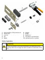
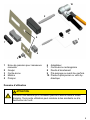
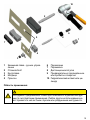
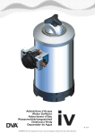
Bedienungsanleitung
Quadrat,- Rechteck- und Formlocher
für Hand- oder Hydraulikbetätigung
Operating Instructions
Square, rectangular and form-punched
Can be operated by hand or hydraulics
Mode d‘emploi
Emporte-pièce de carrés, rectangles et de formes
pour manœuvre manuelle et hydraulique
Instrucciones de uso
Taladro para perforación cuadrada, rectangular y conformada
de accionamiento manual o hidráulico
Инструкция по эксплуатации
Инструмент для вырубки отверстий квадратной, прямоугольной и прочих форм
с возможностью ручного и гидравлического управления
R.T.Nr. 4337040000/00/03.07
10
2
6
8
9
7
1
4
3
1
2
3
4
5
5
Druckmutter Handbetätigung
Zugbolzen
Kontermutter
Matrize
Stempel
6
7
8
9
10
Adapter
Brücke
Distanzbuchse
Vorgebohrtes oder gestanztes Loch
Hydraulikstanze oder Zylinder
Anwendungsbereich
VORSICHT
Das Werkzeug ist nur für die in der Betriebsanleitung beschriebene Anwendung bestimmt. Eine andere Verwendung kann zu Unfällen oder Zerstörung des Werkzeugs führen.
Wartung
Das Werkzeug muss in Abhängigkeit der Einsatzhäufigkeit und Beanspruchung
regelmäßig auf einwandfreie Funktion geprüft werden. Sollten entsprechende
Prüfungen vor Ort nicht möglich sein, können diese vom Hersteller vorgenommen
werden.
Reparaturen
VORSICHT
Das Werkzeug darf nur durch eine Elektro-Mechanikerfachkraft bzw.
durch den Hersteller repariert werden, andernfalls können Unfälle für den
Betreiber entstehen.
Hydraulikbetätigung
Vorbohren mit Spiralbohrer oder Mehrstufenbohrer.
Bei Universal-Werkzeugen die Druckmutter (1) vom Zugbolzen (2) entfernen. Den
Adapter (6) mit dem Innengewinde auf das lange Gewinde vom Zugbolzen aufdrehen.
Den Zugbolzen mit dem Adapter in das Aufnahmegewinde der Stanze oder des Zylinder einschrauben. Geeignete Distanzbuchse (8) auf den Zugbolzen stecken und
am Zylinder ansetzen. Der Einsatz einer Distanzbuchse ist unbedingt erforderlich.
Die Matrize (4) unverkantet auf den Zugbolzen aufsetzen. Den Zugbolzen durch
das vorgebohrte Loch des Werkstücks stecken. Den Stempel (5) von der Rückseite
unverkantet auf den Zugbolzen aufsetzen. Die Kontermutter (3) oder Brücke (7) mit
allen Gewindegängen auf den Zugbolzen zum Stempel hin aufschrauben. Die Brücke muss ganzflächig am Stempel anliegen. Das Werkzeug mit den 4 Markierungen
auf der Matrize am Fadenkreuz auf dem Werkstück ausrichten.
Ventilrad schließen. Pumpenkörper mit einer Hand festhalten und langsam pumpen.
Nach wenigen Hüben ist der Stanzvorgang beendet. Den Stempel ganz durch das
Blech durchziehen. Nach dem Stanzvorgang den Hydraulikzylinder entlasten und
die Kontermutter/Brücke lösen und den Stempel sowie die Matrize vom Zugbolzen
entfernen. Der Stanzabfall fällt seitlich ganz leicht aus der Matrize. Ventilrad öffnen.
Die eingebaute Feder drückt den Kolben wieder in die Ausgangsstellung zurück.
Rundstempel abschrauben bzw. Kontermutter lösen. Stanzabfall aus der Matrize
entfernen.
Handbetätigung
Die Druckmutter (1) auf das lange Gewinde vom Zugbolzen (2) aufdrehen.
Die Matrize (4) unverkantet auf den Zugbolzen aufsetzen. Den Zugbolzen (2) durch
das vorgebohrte Loch am Werkstück stecken. Den Stempel (5) von der Rückseite
unverkantet auf den Zugbolzen aufsetzen. Die Kontermutter (3) mit allen Gewindegängen auf den Zugbolzen (2) zum Stempel (5) hin aufschrauben. Das Werkzeug
mit den 4 Markierungen auf der Matrize am Fadenkreuz auf dem Werkstück ausrichten. Mit dem Schraubenschlüssel die Druckmutter (1) langsam betätigen. Darauf
achten, dass sich das Werkzeug nicht verdreht. Den Stempel ganz durch das Blech
durchziehen. Nach dem Stanzvorgang die Kontermutter lösen und den Stempel
sowie die Matrize vom Zugbolzen entfernen. Der Stanzabfall fällt seitlich ganz leicht
aus der Matrize.
VORSICHT
Nur soweit stanzen bis das Werkstück durchgestanzt ist. Unbedingt vermeiden, dass der Stempel innen auf der Matrize aufsitzt.
Versetztes Stanzen (Nibbeln) ist nicht möglich und würde das Werkzeug
zerstören.
HINWEIS
Zugbolzen, Gewinde, Schneidkanten und Führungen sollten immer eingeölt oder gefettet werden Stempel, Matrizen und Muttern lassen sich
leichter bewegen und der Verschleiß wird erheblich reduziert.
Je nach Abstumpfungsgrad das Werkzeug rechtzeitig nachschärfen lassen.
10
2
6
8
9
7
1
4
3
1
2
3
4
5
5
Hand operation of the pressure nut
Tension bolt
Lock nut
Die
Stamp
6
7
8
9
10
Adapter
Bridge
Spacer nut
Pre-drilled or punched hole
Hydraulic punch or cylinder
Fields of application
CAUTION
The tool is intended for use only as described in the operating instructions. Any other form of usage can lead to accidents or destruction of the
tool.
Maintenance
The tool must be checked regularly, depending on how often it is used, to ensure
that it is functioning flawlessly. If it is not possible to carry out the appropriate checks
on site, they can be conducted by the manufacturer.
Repairs
CAUTION
Repairs to the tool must always be carried out by an electrical or mechanical technician, or by the manufacturer. Otherwise operator accidents
may occur.
Hydraulic operation
Drill holes beforehand with a spiral or multiple-step drill bit.
With universal tools, remove the presure nut (1) from the tension bolt (2). Screw the
adapter (6) with the inner threads onto the long threads from the tension bolt.
Screw the tension bolt with the adapter into the receptacle threads of the punch.
Put the correct spacer nut (8) onto the tension bolt and then attach to the cylinder. It
is absolutely necessary to use a spacer nut. Place the die (4) onto the tension bolt
so that it is not wedged in. Put the tension bolt into the pre-drilled hole on the work
piece. Place the stamp (5) on the tension bolt. The rear side of the punch should not
be wedged. Screw the lock nut (3) or bridge (7) with all threads onto the tension bolt
to the stamp. The bridge link must sit flush against the stamp. Align the tool (with
the four marks on the die) with the work piece, using the cross-hairs.
Close the valve wheel. Hold the pump body with one hand, and pump slowly. The
punching process is completed after a few strokes. Pull the stamp completely
through the sheet. After the punching process, release the hydraulic cylinder. Detach the lock nut/bridge and remove the stamp and the die from the tension bolt.
Residue from the punching will fall easily from the die in a lateral direction. Open the
valve wheel. The built-in spring presses the plunger back into the starting position.
Screw off the round stamp and remove the lock nut. Remove punch residue from
the die.
Hand operation
Screw the lock nut (1) off of the long threads of the tension bolt (2).
Place the die (4) onto the tension bolt so that it is not wedged in. Put the tension
bolt into the pre-drilled hole on the work piece. Place the stamp (5) on the tension
bolt. The rear side of the punch should not be wedged. Screw the lock nut (3) or
bridge (7) with all threads onto the tension bolt to the stamp. Align the tool (with the
four marks on the die) with the work piece, using the cross-hairs. Use the spanner
wrench to slowly move the pressure nut (1). Make sure that the tool itself does not
twist. Pull the stamp completely through the sheet. After the punching process, detach the lock nut and remove the stamp and die from the tension bolt. Residue from
the punching will fall easily from the die in a lateral direction.
CAUTION
Only continue with the punching process until the work piece is punched
though. It is very important to avoid that the inside of the stamp rests on
the die.
Offset stamping (nibbling) is not possible, and will destroy the tool.
Important!
NOTICE
Tension bolts, threads, cutting edges and guides should always be oiled
or greased. The stamps, dies and nuts will then move more freely and
friction will be significantly reduced.
The tool should be sharpened regularly, at intervals which depend on how
dulled the edges are.
10
2
6
8
9
7
1
4
3
1
2
3
4
5
5
Ecrou de pression pour manœuvre
manuelle
Goujon
Contre-écrou
Matrice
Poinçon
6
7
8
9
10
Adaptateur
Contre-écrou rectangulaire
Douille d‘écartement
Pré-perçage ou avant-trou perforé
Presse à poinçonner ou vérin hydraulique
Domaine d‘utilisation
ATTENTION
Cet outil n‘est destiné qu‘à l‘utilisation prévue et décrite dans le mode
d‘emploi. Toute autre utilisation peut conduire à des accidents ou à la
destruction de l‘outil.
Entretien
Le bon fonctionnement de l‘outil doit être contrôlé régulièrement, en fonction de la
fréquence d‘emploi et des efforts auxquels il est soumis. Si les vérifications adéquates ne peuvent être effectuées sur place, le constructeur peut s‘en charger.
Réparations
ATTENTION
L‘outil ne doit être réparé que par un électromécanicien spécialisé ou
par le constructeur. Dans le cas contraire il pourrait se produire des accidents.
Manœuvre hydraulique
Percer un avant-trou à l‘aide d‘un foret hélicoïdal ou étagé.
Sur les outils universels, ôter l‘écrou de pression (1) du goujon (2). Visser l‘adaptateur (6) par le taraudage sur le filetage long du goujon.
Visser le goujon avec l‘adaptateur dans le filetage de la presse à estamper ou du
vérin. Enfiler la douille d‘écartement (8) qui convient sur le goujon et l‘appliquer sur
le cylindre. L‘emploi d‘une douille d‘écartement est impératif. Enfiler sur le goujon
la matrice (4) bien droite. Passer le goujon par l‘avant-trou de la pièce d‘œuvre.
Appliquer le poinçon (5) par l‘arrière sur le boulon, bien droit. Visser le contre-écrou
(3) ou le contre-écrou rectangulaire (7) avec tous les filets sur le goujon, vers le
poinçon. Le contre-écrou rectangulaire doit reposer sur toute la surface le poinçon.
Orienter l‘outil avec les 4 repères de la matrice sur le réticule de la pièce d‘œuvre.
Fermer la manette de soupape. Tenir d‘une main le corps de pompe et pomper
lentement. Après quelques coups, le cycle de poinçonnage est terminé. Passer
complètement le poinçon à travers la tôle. Une fois le cycle de poinçonnage terminé, décharger le vérin hydraulique, enlever le contre-écrou et retirer du goujon le
poinçon et la matrice. La débouchure sort très facilement sur le côté de la matrice.
Ouvrir la manette de la soupape. Le ressort intégré repousse le piston dans sa position d‘origine.
Dévisser le poinçon rond ou desserrer le contre-écrou. Ôter de la matrice la débouchure.
10
Manœuvre manuelle
Visser l‘écrou de pression (1) sur le long filetage du goujon (2).
Enfiler sur le goujon la matrice (4) bien droite. Passer le goujon (2) par l‘avanttrou de la pièce d‘œuvre. Appliquer le poinçon (5) par l‘arrière sur le boulon, bien
droit. Visser le contre-écrou (3) avec tous les filets sur le goujon, vers le poinçon.
Orienter l‘outil avec les 4 repères de la matrice sur le réticule de la pièce d‘œuvre.
A l‘aide d‘une clé plate, tourner lentement l‘écrou de pression (1). Veiller à ce que
l‘outil ne se décale pas en rotation. Passer complètement le poinçon à travers la
tôle. Une fois le cycle de poinçonnage terminé, desserrer le contre-écrou et retirer
du goujon le poinçon et la matrice. La débouchure sort très facilement sur le côté de
la matrice.
ATTENTION
Ne poinçonner que jusqu‘à ce que la pièce d‘œuvre soit perforée complètement. Eviter à tout prix que le poinçon ne repose en interne sur la
matrice.
Un poinçonnage décalé (grignotage) n‘est pas possible et détruirait l‘outil.
AVIS
Goujon, filetage, bords de coupe et guides doivent toujours être lubrifiés
ou graissés. Le poinçon, les matrices et écrous sont ainsi plus mobiles et
l‘usure est considérablement réduite.
Selon le degré d‘usure, faire aiguiser l‘outil en temps utiles.
11
10
2
6
8
9
7
1
4
3
1
2
3
4
5
5
Tuerca de presión, accionamiento
manual
Perno de tracción
Contratuerca
Matriz
Sello
6
7
8
9
10
Adaptador
Puente
Manguito distanciador
Agujero perforado o punzonado
Perforador hidráulico o cilindro
Uso previsto
PRECAUCIÓN
Esta herramienta sólo está prevista para su uso conforme a estas instrucciones. Cualquier uso distinto al previsto puede causar accidentes o
la destrucción de la herramienta.
12
Mantenimiento
El buen funcionamiento de la herramienta herramienta debe comprobarse periódicamente, dependiendo de la frecuencia de uso y los esfuerzos a los que se vea sometida. Si no fuera posible realizar las comprobaciones correspondientes “in situ”,
éstas podrán ser realizadas en el taller del fabricante.
Reparaciones
PRECAUCIÓN
La herramienta sólo debe ser reparada por un electricista-mecánico
autorizado o por el fabricante. De lo contrario, el usuario puede sufrir un
accidente.
Accionamiento hidráulico
Taladro con punta espiral o taladro múltiple.
En el caso de herramientas universales, retire la tuerca de presión (1) del perno de
tracción (2). Enrosqe el adaptador (6) con el roscado interior sobre el roscado alargado del perno de tracción.
Atornille el perno de tracción con el adaptador en el roscado de inserción de la
cuchilla o del cilindro. Inserte el manguito distanciador 8) en el perno de tracción
y en el cilindro. Es necesario utilizar siempre un manguito distanciador. Coloque la
matriz (4) sin inclinarla en el perno de tracción. Inserte el perno de tracción a través
del agujero perforado de la pieza de trabajo. Coloque el sello (5) de la parte trasera
sin inclinarlo en el perno de tracción. Atornille la contratuerca (3) o el puente (7) con
todas las roscas helicoidales en el perno de tracción en la dirección del sello. El
puente debe quedar colocado con toda su superficie en contacto con el sello. Posicione la herramienta con las 4 marcas sobre la matriz en el retículo sobre la pieza
de trabajo.
Cierre la rueda de la válvula. Sostenga el cuerpo de la bomba con una mano y
bombee poco a poco. Después de unas cuantas carreras finalizará el proceso de
corte. Pasar el sello completamente a través de la chapa. Después del proceso de
corte, descargue el cilindro hidráulico y suelte la contratuerca/puente y extraiga el
sello y la matriz del perno de tracción. Los restos de corte caen a un lado fácilmente de la matriz. Abra la rueda de la válvula. El resorte integrado vuelve a presionar
el émbolo hasta devolverlo a la posición inicial.
Desatornille el sello redondo o suelte la contratuerca. Retire los residuos de corte
que han quedado en la matriz.
13
Accionamiento manual
Enrosqe la tuerca de presión (1) en el roscado alargado del perno de tracción.
Coloque la matriz (4) sin inclinarla en el perno de tracción. Inserte el perno de tracciónn(2) a través del agujero perforado de la pieza de trabajo. Coloque el sello (5)
de la parte trasera sin inclinarlo en el perno de tracción. Atornille la contratuerca (3)
con todas las roscas helicoidales en el perno de tracción en la dirección del sello
(5). Posicione la herramienta con las 4 marcas sobre la matriz en el retículo sobre
la pieza de trabajo. Accione lentamente la tuerca de presión (1) mediante la llave
de ajuste. Procure que la herramienta no se desajuste. Pasar el sello completamente a través de la chapa. Después del proceso de corte, suelte la contratuerca
y extraiga el sello y la matriz del perno de tracción. Los restos de corte caen a un
lado fácilmente de la matriz.
PRECAUCIÓN
Corte sólo hasta que haya perforado la pieza. Evite siempre que el sello
quede encastrado en el interior de la matriz.
No es posible perforar (punzonar) con la máquina desequilibrada o desajustada, ya que ello destruiría la herramienta.
AVISO
Los pernos de tracción, roscados, bordes de corte y guías deben lubricarse con aceite y engrasarse periódicamente. Los sellos, matrices y tuercas podrán desplazarse mejor y ello reducirá notablemente su desgaste.
Afile la herramienta siempre que ello sea necesario.
14
10
2
6
8
9
7
1
4
3
1
2
3
4
5
5
Зажимная гайка - ручное управление
Стяжной болт
Контргайка
Матрица
Пуансон
6
7
8
9
Переходник
Перемычка
Дистанционная втулка
Предварительно просверленное
или пробитое отверстие
10 Гидравлический штамп или цилиндр
Область применения
Инструмент предназначен только для описанного в данной инструкции по эксплуатации применения. Любое другое использование может привести к несчастным случаям или разрушению инструмента.
15
Техобслуживание
Инструмент нуждается в регулярной проверке на предмет правильного функционирования в зависимости от частоты использования и нагрузки. Если
выполнение соответствующих проверок на месте невозможно, они могут быть
выполнены производителем.
Ремонт
Ремонт инструмента может выполняться только квалифицированным
электромехаником либо самим производителем, в противном случае
существует опасность несчастного случая для пользователя.
Гидравлическое управление
Предварительное сверление спиральным сверлом или многоступенчатым
сверлом.
На универсальных инструментах снимите зажимную гайку (1) со стяжного
болта (2). Накрутите переходник (6) с внутренней резьбой на длинную резьбу
стяжного болта.
Вкрутите стяжной болт с переходником в приемную резьбу штампа или цилиндра. Установите подходящую дистанционную втулку (8) на стяжной болт и соедините с цилиндром. Использование дистанционной втулки строго обязательно. Установите матрицу (4) на стяжной болт, не допуская перекосов. Вставьте
стяжной болт через предварительно просверленное отверстие заготовки. Установите пуансон (5) с задней стороны на стяжной болт, не допуская перекосов.
Накрутите контргайку (3) или перемычку (7) всеми витками резьбы на стяжной
болт по направлению к пуансону. Перемычка должна всей поверхностью прилегать к пуансону. Выверите инструмент с помощью 4 меток на матрице по
перекрестию линий на заготовке.
Закройте колесо вентиля. Удерживая корпус насоса, медленно качайте. Процесс вырубки будет завершен после выполнения нескольких ходов. Полностью
протяните пуансон через листовой металл. После вырубки разгрузите гидравлический цилиндр и открутите контргайку/перемычку, после чего снимите пуансон и матрицу со стяжного болта. Отходы от вырубки свободно выпадут сбоку
из матрицы. Откройте колесо вентиля. Встроенная пружина снова отожмет
поршень обратно в исходное положение.
Открутите круглый пуансон или отпустите контргайку. Удалите отходы от вырубки из матрицы.
16
Ручное управление
Накрутите зажимную гайку (1) на длинную резьбу стяжного болта (2).
Установите матрицу (4) на стяжной болт, не допуская перекосов. Вставьте
стяжной болт (2) через предварительно просверленное отверстие в заготовке.
Установите пуансон (5) с задней стороны на стяжной болт, не допуская перекосов. Накрутите контргайку (3) всеми витками резьбы на стяжной болт (2) по
направлению к пуансону (5). Выверите инструмент с помощью 4 меток на матрице по перекрестию линий на заготовке. С помощью гаечного ключа медленно поворачивайте зажимную гайку (1). Следите за тем, чтобы инструмент не
проворачивался. Полностью протяните пуансон через листовой металл. После
вырубки открутите контргайку и снимите пуансон и матрицу со стяжного болта.
Отходы от вырубки свободно выпадут сбоку из матрицы.
Вырубку производите только до тех пор, пока не будет прорублена
заготовка. Ни в коем случае не допускайте, чтобы пуансон находился
изнутри на матрице.
Смещенная относительно оси вырубка (вибрационная вырубка) невозможна и ведет к разрушению инструмента.
Стяжной болт, резьбы, режущие кромки и направляющие должны
быть постоянно смазаны маслом или консистентной смазкой. Это
обеспечивает более свободный ход пуансонов, матриц и гаек и значительно снижает износ.
Инструмент нуждается в своевременной заточке по мере затупления.
17
18
19
Weidmüller Interface GmbH & Co. KG
Klingenbergstrasse 16
D-32758 Detmold
Phone: +49 5231 14-0
Fax:
+49 5231 14-2083
e-mail: [email protected]
www. weidmueller.com