1
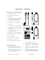
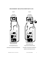
m
co
.
k
ni
o
r
kt
e
el
s
j
.h
w
ww
EUROTEST
EUROTEST 701/702 S
OPERATING INSTRUCTIONS
( Version "A3/C/S2" )
EUROTEST 701/702 S (A3/C/S2)
1
© HJS ELEKTRONIK
TABLE
CHAPTER/PAGE
2
FUNCTIONAL ELEMENTS
3
SAFETY PRECAUTIONS
4
UTILITZATION
4
SAFETY ELEMENTS
4
LITERATURE
5
MEASUREMENTS:
PROTECTIVE CONDUCTOR RESISTANCE R-PE
6,7
INSULATION RESISTANCE R-ISO
8,9
PROTECTIVECONDUCTORCURRENTI-SL (direct method)
10
PROTECTIVECONDUCTORCURRENTI-SL (equ.leakage curr.method) 11
TOUCH CURRENT I-BR (direct method)
12
TOUCH CURRENT I-BR (equ. leakage curr. method)
13
TECHNICAL SPECIFICATION
14
LIMITS +DISPLAY OF LIMIT VALUES
15
DISPLAY OF MEASUREMENT VALUES
15
GENERAL INFORMATION
Es irrt der
Mensch
solang
er
strebt
jwg
15,16
REPAIR SERVICE
16
CALIBRATION SERVICE
16
DATA INTERFACE
16
WARRENTY
16
CALIBRATION RECORD
17
MADE IN GERMANY
...we do our very best
2
EUROTEST 701/702 S (A3/C/S2)
© HJS ELEKTRONIK
FUNCTIONAL
ELEMENTS
DESCRIPTION OF FUNKTIONSELEMENTE
(1)
MEASURING INSTRUMENT
(2)
Test socket for R-PE, R-ISO, and I-EA measurement.
(3)
Mains connector.
(4)
Test lead w. crocodile clip for R - PE measurement.
(The line resistance is length independently compensated for > fourpole measurement)
(5)
PLL-controlled LCD for display of values.
(5')
Limit display, 3 LEDs per measurement range
(6)
Range selector.
(7)
I-ABL terminal for leakage current measurement.
(8)
L/N terminal for R-ISO and I-EA measurement.
Connected to the test socket (2) via the outer
conductors L and N .
(9)
PEi terminal for R-PE measurement only . Connected to PE in the test socket (2) .
(9')
R-ISO, and I-EA.
PEu terminal for R - PE,
measurement. Connected to PE in the test socket (2).
(10)
Test lead with probe tip.
(11)
Test lead with probe tip.
(12)
KROKO terminal for R-PE measurement.
(13)
Data interface to PC or notebook
(14)
Switch for (de)activating the PE in the test socket.
Z2
insulating pad for tester and test sample.
Z3
Test adapter for R-PE, R-ISO, and I-EA measurement. (CEE 3L/N/PE on earthing-contact type L/N/
PE) (i.V.)
ACCESSORIES (OPTIONAL)
Z0.1
Software set: WINDOWS analysis program +
interface adaptor (Z0.2) for the preparation of test
record.
Z4
Test adapter with RCD for leakage current measurement. (3 - ph.: CEE 3L/N/PE on CEE 3L/N/
PE)(i.V.)
Z1
Test adapter with RCD, for leakage current measurement. (1- ph.: earthing-contact type L/N/PE on
earthing-contact type L/N/PE)
Z5
Set of test leads: lead with crocodile clip , as (4), but
2 m long + Y adapter (Z6) for bridging longer
distances between the measurement points.
EUROTEST 701/702 S (A3/C/S2)
© HJS ELEKTRONIK
3
SAFETY
SAFETYPRECAUTIONS
Before taking the INSTRUMENT into operation, make sure
that the instrument's nominal voltage matches the mains
voltage.
The INSTRUMENT serves for electronically testing electrical devices in accordance with DIN VDE 0701/ DIN VDE
0702. It has been manufacutured and tested as defined in
DIN VDE 0404, DIN EN 61010, DIN EN 61557, and has been
shipped in a safety technological perfect condition.
To maintain this conditition and ensure a safe operation,
the user has to observe the warnings and notes included
in these operating instructions :
ATTENTION
This INSTRUMENT may be exclusively used for electrical
testings. Please note that the respective standards may
require additional manual and visual inspections, temperature, functional, and drop tests etc. depending on the
type of test sample.
ATTENTION
The INSTRUMENT may be exclusively connected to an
intact and safe 230V AC mains. The mains socket must
provide for an intact connection of the protective conductor (earthing -contact type PE).
ATTENTION
A voltage supply to the PE at the mains socket may result
in incorrect leakage current measurements.
ATTENTION
At a faulty power supply, the INSTRUMENT and the test
sample are to be immadiately disconnected from the
mains.
ATTENTION
Using the INSTRUMENTS for measurements in electrical equipments is not permissible.
ATTENTION
Carrying out measurement in the immediate vicinity of electrical or electromagneticfieldsaswellasHF-emittingdevicesorequipmentshouldbe
avoided.
4
EUROTEST 701/702 S (A3/C/S2)
ATTENTION
Please account for the occurence of unexpected voltages
at the test samples. The anti-radio-inference-capcitor may
be charged after the insulation resistance has been measured.
Please, always check the test sample's protective conductor resistance R - PE first .
Without an intact connection of the protective conductor
to the test sample the results of an insulation resistance
and protective conductor current measurement are meaningless.
If a safe operation of the INSTRUMENT seems to be no
longer ensured the INSTRUMENT is to be taken out of
operation and has to be protected against accidental use.
It is to be assumed that a safe operation of the INSTRUMENT is no longer ensured if the INSTRUMENT
>
>
>
>
is visibly damaged,
does not work any more,
has been stored under unfavourable conditions,
has been subject to heavy strain during transport.
UTILIZATION
The INSTRUMENT is exclusively suited for the testing and
measurement on repaired or modified electrical devices
as set out in DIN VDE 0701 and for repetitive testings
according to DIN VDE 0702 .
Following these provisions i.a. the protective conductor
resistance R - PE, the insulation resistance R - ISO, the
protective conductor current I - SL, the touch current I - BR
and the non prevailence of stress I - SF (T240) is to be
tested.
PROTECTIVE ELEMENTS
The INSTRUMENT features a PE connector for the protective conductor and is therefore rated protection class I.
ThePE connector is only needed for the leakage current
measurement (direct method).
In the I - ABL position, it is connected to the INSTRUMENT's
chassis via reversible protective elements. In case of
overload voltages of more than 253 V all 3 limit LEDs will
start flashing signalling the reponse of the protective
elements.
In all other switch positions the INSTRUMENT is galvanically disconnected from the mains.
© HJS ELEKTRONIK
L I T E R A T U R E
REFERENCE STANDARDS
SUGGESTED READING
VDE 0100 Teil 200
Errichten von Starkstromanlagen
mit Nennspannungen bis 1000 V
Bödeker:
Prüfung ortsveränderlicher Geräte,
Verag Technik
VDE 0104
Errichten und Betreiben elektrischer
Prüfanlagen
Bödeker:
Der Prüfplatz in der Elektrowerkstatt,
Verag Technik
VDE 0105 Teil 100
Betrieb von elektrischen Anlagen
VDE 0106 Teil 1
Schutz gegen elektrischen Schlag
Bödeker,
Kindermann,
Kammerhoff,
Matz:
Prüfung elektrischer Geräte nach
DIN VDE 0701, 0702, VDE 0751
Anwendung in der Praxis
VDE-Verlag (08-2001)
VDE 0404 Teil 1
Allgemeine Festlegungen
VDE 0404 Teil 2
Geräte für Wiederholungsprüfung.
Bödeker,
Kindermann:
Fachpublikationen zum Thema:
VDE 0411
Sicherheitsbest. für el. Messgeräte
VDE 0413
Geräte zum Prüf. v. Schutzmaßnahmen
VDE 0701 Teil 1
Allgemeine Anforderungen
VDE 0701 Teil 2
Rasenmäher und Gartenpflegegeräte
VDE 0701 Teil 3
Bodenreinigungsgeräte und Maschinen
VDE 0701 Teil 4
Sprudelbadgeräte
VDE 0701 Teil 5
Großküchengeräte
VDE 0701 Teil 6
Ventilatoren und Dunstabzugshauben
VDE 0701 Teil 7
Nähmaschinen
VDE 0701 Teil 8
Ortsfeste Wasserwärmer
VDE 0701 Teil 200
Netzbetriebene elektronische Geräte
VDE 0701 Teil 240
Datenverarb-Einrichtg u.Büromasch.
VDE 0702 Teil 1
Wiederholungsprüfungen
VDE 0711 Teil 1
Leuchten, allgemeine Anforderungen
VDE 0751 Teil 1
Wiederholungsprüfungen von
med. elektrischen Geräten
VDE 0805
Sicherheit von el. Büromaschinen
VDE 1000 Teil 10
DIN EN 13306
Prüfung el. Geräte nach Instands..
ep 09/2000
Kennwerte für den Ableitstrom......
de 09+10/2000
Prüfgeräte nach DIN VDE 0404....
ep 09/1999
Pflicht zur Wiederholungsprüfung..
ep 01/2000
Umfang zur Wiederholungsprüfg...
ep 02/2000
Wiederholungsprüfg nach VBG4...
ep 03/2000
PC: - ortsfest oder ortsveränderl..?..
ep 09/2000
L-Stromzange u.Fehlerstrommessg.
ep 12/2000
Messung des Ersatz-Ableitstroms
de 01/2001
Prüfplätze ohne Berührungsschutz
ep 04/2001
Egyptien:
Unterweisung in der Elektropraxis
Verlag Technik
Jeiter:
Das neue Gerätesicherheitsgesetz,
Verlag C.H.Beck
ZVEH (Hrsg):
Handwerksordnung,
Verlag Heider
Honig:
Handwerksordnung, Kommentar,
Verlag C.H.Beck
Anforderungen an die im Bereich
der Elektrotechnik tätigen Personen
Gothsch:
VBG4, Elektrische Anlagen und Betriebsmittel, BG F+E (Hrsg), Köln
Begriffe der Instandhaltung
Rosenberg
VDE-Prüfung nach VBG4/VDE-Verl.
EUROTEST 701/702 S (A3/C/S2)
© HJS ELEKTRONIK
5
MEASUREMENT: PROTECTIVE CONDUCTOR RESISTANCE R-PE
MEASUREMENT: PROTECTIVE CONDUCTOR
RESISTANCE R-PE
(Sample connections fig. 1, 2, and 3 )
Figure 1
Test Sample
Protection Class I
The protective conductor resistance R - PE must not be
measured until after a visual inspection of the instrument
and all parts representing a possible electrical or mechanical danger or risk of fire!
As for instruments classified protection class I the low ohm
passage of the PE between the test sample's PE output and
its housing or all touchable and conductive parts connected to the PE is measured.
> The test sample may be "in operation" or diconnected
from mains.
> During this measurement, the power cord has to be
sectionwise moved over the entire length especially near
the connection points.
> Please note that with hard-wired devices and/or such
being "in operation" parallel earth connections and protective conductor currents may negatively affect the measurement results.
The line resistances of the test leads are length independently compensated for (fourpole measurement), however, if adapters or adapter leads are used this compensation is ineffective.
Therefore, we recommend to determine the adapter leads'
resistance before measuring the R - PE and to account for
this value when documenting the measurement results.
If the protection class I test sample features no mains plug
- e.g. stationary devices - or if the plug does not match the
test socket, the measurement can be made using the
terminals PEi+PEU .
In this case, the PE in the test socket has to be deactivated
via the selector (14) .
Alternatively to the test leads supplied the test lead with
crocodile clip (Z5) and the Y-adaptor (Z6) should be used
for bridging larger distances between the measurement
points.
For limits and the display of limit values please refer to:
page 15
6
EUROTEST 701/702 S (A3/C/S2)
Selector Position: R-PE
Test sample with mains plug
Test sample "out of operation"
© HJS ELEKTRONIK
MEASUREMENT: PROTECTIVE CONDUCTOR RESISTANCE R-PE
Figure 2
Figure 3
Test Sample
Protection Class I
Test Sample
Protection Class I
extension
cord
Selector position: R-PE
Selector position: R-PE
Test sample with mains plug
Exception: Interruption impossible
Test sample "out of operation"
Test sample "in operation"
EUROTEST 701/702 S (A3/C/S2)
© HJS ELEKTRONIK
7
MEASUREMENT: INSULATION RESISTANCE R-ISO
MEASUREMENT:
INSULATION RESISTANCE R-ISO
(Sample connection figure 4, 5, and 6)
Figure 4
Test Sample
Protection Class I
The R-ISO is measured as follows:
a) for protection class I devices: between the test sample's
PE connector and all active parts,
b) for protection class I devices between all active parts as
well as all touchable conductive parts not being connected to PE .
c) for protection class II devices: between all active parts
as well as all touchable conductive parts or such being
connected to the housing.
> The test sample is "out of operation" but switched on.
> Devices to be used in water must (or can) be covered with
water during the measurement ! (see standards)
> The measurement is to be made in all switch positions
(step-by-step systems, relays, controllers, temperature
switches etc.) .
> The correct measurement value is the smallest ! value
measured.
> 500 VDC test voltage! Touching the test lead tips may
result in shock reactions poses, however, no hazard at all!
If the protection class I or II Prüfling has no mains plug - e.g.
stationary devices - or if the plug does not match the test
socket, the measurement can also be made via the terminals PEU + L/N .
(Applies analogously to polyphase test samples)
If the measurement is carried out in accordance with b) on
protection class I devices with an earthing -contact type
plug, the PE in the test socket has to be deactivated via
the selector (14).
For limits and the display of limit values see page 15
Selector position: R-ISO
Exception: test sample without mains plug
Test sample "out of operation" but switched on
8
EUROTEST 701/702 S (A3/C/S2)
© HJS ELEKTRONIK
MEASUREMENT: INSULATION RESISTANCE R-ISO
Figure 5
Figure 6
Test Sample
Protection Class II
Test Sample
Protection Class I
Selector position: R-ISO
Selector position: R-ISO
Test sample with mains plug
Exception: hard-wired DS test sample
Test sample "out of operation", but switched on
Test sample "out of operation" but switched on
Attention: Set test sample stress-free!
EUROTEST 701/702 S (A3/C/S2)
© HJS ELEKTRONIK
9
MEASUREMENT: PROTECTIVE CONDUCTOR CURRENT I-SL
MEASUREMENT: PROTECTIVE CONDUCTOR
CURRENT I-SL (direct method*)
(Sample connections: figure 7)
Figure 7
Test Sample
Protection Class I
If operated set out herein, the protection conductor current
I-SL is a leakage current of a protection class I device
flowing via the insulation and protective conductor to the
earth.
The measurement has to be made if there is no other
chance to ensure that all parts affected by the mains
voltage have been tested during the R - ISO measurement
of if the R - ISO test has not been passed or carried out.
Page 15!
> Test sample and INSTRUMENT are connected to the
same circuit.
> During this measurement, the test sample is "in operation"!
> If possible, the measurement is made in all! plug
positions of the test sample's mains plug and in all selector
positions (step-by-step systems, relays, controllers, temperature switches etc.). The correct measurement value
is the highest value measured.
> The test sample must be set insulated! Except for the
power cord no other conductive connections to other devices or the earth potential may be made.
Measuring the protective conductor current I-SL using this
direct method should be made using the measurement
adapter (Z1) with integrated RCD because of the dangers
resulting from touching possibly defect test samples. Connect the test lead with the adapter first and then the
adapter/test sample to the mains.
*) This method is also called "direct method " since the test
circuit is directly connected to the mains. Using the direct
measurement method for the exclusive documention of
the test sample's insulating capacity is permissible.
For limits and the display of limit values see page 15
Selector position: I-ABL
Test sample with mains plug
Test sample "in operation"
Measurement made using the direct method
10
EUROTEST 701/702 S (A3/C/S2)
© HJS ELEKTRONIK
MEASUREMENT: PROTECTIVE CONDUCTOR CURRENT I-SL
Figure 8
Test Sample
Protection Class I
MEASUREMENT: PROTECTION CONDUCTOR
I-SL (equivalent leakage current method*)
(Sample connection figure 8)
If the protective conductor current I-SL is measured using
the "equivalent leakage current method ", the R-ISO test
has to be passed first!
This measurement is made:
on protection class I devices: between the test sample's
PE-connector and all active parts.
> The test sample is "out of operation" but switched on.
> The measurement is made in all selector positions (stepby-step systems, relays, controllers, temperature switches
etc.). The correct measurement value is the highest value
measured.
> As for test samples with switches controlling all poles
and symetric capacitive power input, the measurement
values may be divided by 2! (See standard)
If the protection class I test sample has no mains plug - e.g.
stationary devices - or if the plug does not match the test
socket, the measurement can be made using the terminals
PEU + L/N .
(Applies analogously to polyphase test samples)
*) When using the "equivalent leakage current method" the
test circuit is not directly connected to the mains and the
"leakage current" is generated by the INSTRUMENT.
The word "equivalent" refers to the fact that in this test an
artifical mains network is simulated.
Selector position: I-EA
This method has its advantages and disadvantages. The
advatages: The test setting is small, cost efficient, simple
and safe application as well as a high reproductivity of the
measurement values. The disadvantages: The test can
only be made if the R-ISO test has been passed and all
switches can be switched on..
For limits and the display of limit values see page 15
Test sample with mains plug
Test sample "out of operation" but switched on
Measurement using the eq. leakg. current method
EUROTEST 701/702 S (A3/C/S2)
© HJS ELEKTRONIK
11
MEASUREMENT: TOUCH CURRENT I-BR
MEASUREMENT: TOUCH CURRENT I-BR
(direct method*)
(Sample connection figure 9)
Figure 9
Test Sample
Protection Class I
The touch current I-BR is a leakage current generated at
proper operation of the device. It flows through the insulation, touchable conductive parts and the person touching them to the ground.
The measurement is made if it can not be ensured that all
parts affected by the mains voltage have been covered in
the R - ISO test or if the R - ISO has not been passed or
carried out.
The touch current is measured:
Page 15!
a) with protection class I devices: on all touchable conductive parts not being connected to the PE ,
b) with protection class II devices: on all touchable conductive parts.
> Test sample and INSTRUMENT are connected to the
same circuit.
> During the measurement the test sample is "in operation"!
> If possible, the measurement is made in all! plug
positions of the test samples's mains plug and in all
selector positions (step-by-step systems, relays, controllers, temperature switches etc.). The correct measurement value is the highest value measured.
> The test sample must be insulated! Except for the power cord no other conductive connections to other devices or the earth potential may exist.
Measuring the touch current I-BR using this direct method
should be made using the measurement adapter (Z1) with
integrated RCD because of the dangers resulting from
touching possibly defect test samples. Connect the test
lead with the adapter first and then the adapter/test sample
to the mains..
*) This method is also called "direct method " since the test
circuit is directly connected to the mains. Using the direct
measurement method for the exclusive documentation of
the test sample's insulation capacityis permissible.
Selector position: I-ABL
Test sample with mains plug
Test sample "in operation"
For limits and the display of limit values see page 15
Measurement using the direct method
12
EUROTEST 701/702 S (A3/C/S2)
© HJS ELEKTRONIK
MEASUREMENT: TOUCH CURRENT I-BR
Figure 10
Test Sample
Protection Class II
MEASUREMENT: TOUCH CURRENT I-BR
(equivalent leakage current method*)
(Sample connection figure 10)
If the touch current I-BR is measured using the "equivalent
leakage current method" the R-ISO test must have been
passed first!
The touch current I-BR is measured:
a) with protection class I devices: between all active parts
as well as all touchable conductive part not being
connected to the PE,
b) with protection class II devices: between all active parts
as well as all those being in contact with the housing
or being touchable and conductive respectively..
> The test sample is "not in operation" but switched on.
> The measurement is to be made in all selector positions
(step-by-step systems, relays, controllers, temperature
switches etc.) .The correct measurement value is the
highest value measured.
> As for test samples with switches controlling all poles
and symetric capacity power input, the measurement
values may be devided by 2! (See standard)
If the protection class I or II test sample has no mains plug
-e.g. stationary devices - or if the plug does not match the
test socket, the measurement can also be made using the
terminals PEU + L/N .
(Applies analogously to polyphase test samples)
If the measurement on protection class I devices with
earthing-contact type plug is made in accordance with a)
the PE in the test socket has to be deactivated via the
selector (14) .
Selector position: I-EA
Test sample with mains plug
Test sample "out of operation", however, switch on
*) When using the "equivalent leakage current method" the
test circuit is not directly connected to the mains and the
"leakage current" is generated within the INSTRUMENT .
(also see p. 11)
NOTE: In DIN VDE 0701 part 240 the touch current I-BR is
called "stress-free I-SF" !
For limits and the display of limit values see page 15.
Measurement using the eq. leakg. current method
EUROTEST 701/702 S (A3/C/S2)
© HJS ELEKTRONIK
13
TECHNICAL SPECIFICATION
NOMINAL CONDITIONS OF USE
MEASUREMENT RANGE R-PE
ENVIRONMENT
0 .....19,99 MΩ
max. 600 VDC
max. 5 mA
+- 2,5% +2D
+ - 10% +2D
253 V
permanet
POWER
MEASUREMENT RANGE R-ISO
Nominal range of use
open-circuit voltage
Short-circuit current
Intrinsic error M. 1) 2)
Operating error M. 2)
Overload value
Overload time
MEASUREMENT RANGE I-EA (Eq. Leakg. Cur. Method)
Nominal range of use
Open-circuit voltage
Short-circuit voltage
Reference voltage / Ri / Rref
Intrinsic error M. 1) 2)
Operating error M. 2)
Overload value
Overload time
0......19,99mA
max. 40 VAC
max. 2 mA
230 VAC /~20 K / ~2 K
+- 2,5% +2D
+ - 10% +2D
253 V
permanent
MESAUREMENTRANGEI-ABL(DirectMethod)
Nominalrangeofuse
Method / Ri
Intrinsic error M. 1) 2)
Operating error M. 2)
Overload value
Overload time
Nominal voltage
Nominal frequency
Curvature
Ambient temperature
0......19,99 Ω
max. 20 VAC
max. 350 mA
+- 2,5% +2D
+ - 10% +2D
./.
./.
Nominal range of use
Open-circuit voltage
Short-circuit current
Intrinsic error M. 1) 2)
Operating error M. 2)
Overload value
Overload time
0......3,99mA
direct, AC+DC /~2 K
+ - 2,5%+2D
+ - 10% +2D
253 V
permanent
Temp. storage
Temp. operation
Accuracy
Humidity
Climate class
Height above sea level
Application
207 V ... 253 V
48 Hz ... 52 Hz
< 10 VA
ELECTRICAL SAFETY
Protection class
I (one)
Nominal voltage
230 V
Test voltage
3,7 KV
Overvoltage category
II
Degree of soiling
2
EMV: emmittance of/immunity from noise acc. DIN EN 61326
MECHANICAL CONSTRUCTION
Display
LCD 3,5 - 13 / PLL gest.
Display of m. values
3LEDinallmeasurementranges
Protection class
Housing IP 40, Conn. IP 20
Dimensions/weight w/o leads
100x195x40mm/~500g
DATA INTERFACE
REFERENCE CONDITIONS
OPERATING ERROR
230 V + - 0,1%
50 Hz + - 0,1%
Sinus, K<0,5%
+23 °C +- 1 K
48% ... 52%
linear
- 20 °C ... + 60 °C
0 °C ... + 35 °C
+ 15 °C ... + 30 °C
no Dew!
2z/0/50/-20/75%
max. 2000 m
only indoor
Nominal voltage
Nominal frequency
Power consumption
If the current exceeds 3,99 mA , the LC display
indivates an overrun condition (I. ) and the 3 LEDs
are flashing. The INSTRUMENT is reset by removing
the load and turning the range selector once.
Nominal voltage
Nominal frequency
Curvature
Ambient temperature
Humidity
Load resistances
207 V ... 253 V
48 Hz ... 52 Hz
Sinus
0 °C ... 35 °C
Type
Format
Connector
seriell
2400, N, 8,1; o.Handshake
Detend-Box 3,5 mm
When documenting the measurement values the
INSTRUMENT's Operating error in relation to the limit
value is tobe accounted for.
When using the analysis program, the abweichung may be
accounted for.
STANDARDS + REGULATIONS APPLYING TO THE PRODUCTION
1) only under reference conditions!
14
2)>20D
EUROTEST 701/702 S (A3/C/S2)
DIN EN 61010-1 / DIN EN 61557-1 / DIN VDE 0404 -1,2
© HJS ELEKTRONIK
GENERAL INFORMATION
DISPLAY OF MEASUREMENT VALUES
In all measurement ranges, the most significant limit
values are displayed via 3 LEDs. For further limit values
refer to the standards. Any changes to the set of limit values
to be displayed, e.g due to modifiied standards, can be
accounted for by replacing a micro chip . (Manufactuer's
service)
R-PE MEASUREMENT RANGE
Display
Cause / Interpretation
"OVERRUN", all 3 limit LED are flashing
R - PE
DISPLAY OF LIMIT VALUES
R - PE > 20 Ω
PE disrupted
>Test sample not connected
Displayed value: 0,30 Ω
1. + 2. limit LEDs are lit
"OVERRUN"
V-Line
Standard
Exception
R-ISO MEASUREMENT RANGE
R - ISO
R - ISO > 20 MΩ
Test sample not connected
Test sample not switched on
All 3 limit LEDs are lit
Sample short-circuited btw. PE + L/N
Displayed value: 0,30 MΩ
All 3 limit LEDs are lit
"OVERRUN", all 3 limit LEDs are lit
PC I
Exception
I-EA MEASUREMENT RANGE (Eq. Leakg. Cur. Method)
I - EA
I - EA > 20 mA
PC II
Sample short-circuited btw. PE + L/N
Terminals PE + L/N short-circuited.
Test sample not connected
Test sample not switched on
Displayed value: 3,50 mA
All 3 limit LEDs are lit
"OVERRUN", all 3 limit LED are flashing
I-BR
I-SL
I-ABL MEASUREMENT RANGE (Direct Method)
I - ABL
(I-SF,part 240)
Sample poses risk of electrical shock,
i.e. current > 4,00 mA!
Disconnect test sample immediately from mains!
Test sample not connected
Test sample "not in operation"
Risk of el. shock (Ideal value)
Displayed value: 0,50 mA
(I-SF,part 240)
I-BR
I-SL
NOTES ON I - ABL MEASUREMENT RANGE
1. + 2. limit LEDs are lit
NOTES ON I - ABL MEASUREMENT RANGE
Leakage current measurements (I-SL,I-BR,I-SF) on test
samples being properly connected to the mains have been
defined as "works carried out in the near of live components" (DIN VDE 0104 and 0105 ). Therefore, the following
safety precautions must be taken i.a.:
Connect RCD in series! (s. accessories Z1/Z4, opt.)
1.) "If the test circuit is directly connected to the low voltage
net RCD protective elements of 10...30 mA must be used"
and 2.) "On test stations with voltages up to 1000 V the
tester's position must be insulated ".(quote: Standard)>>>
Insulate tester's position ! (s. accessories Z2, opt.)
EUROTEST 701/702 S (A3/C/S2)
Insulate test sample!
(s. accessories Z2, opt.)
Ensure proper connection to mains !
© HJS ELEKTRONIK
15
GENERAL INFORMATION
REPAIR SERVICE
WARRANTY
If the hazardfree operation of the INSTRUMENT seems to
be no longer ensured, the INSTRUMENT is to be taken out
of operation and to be protected against accidental use.
A safe operation of the INSTRUMENT is likely to be
impossible if :
Any shortcomings attributable to defective material or poor
workmanship being reported to the manufacturer within 24
months after the INSTRUMENT has been purchased will
be eliminated free of charge. The manufacturer decideds
at his sole discretion whether to repair or replaceme the
respective component or the INSTRUMENT.
> there are visible damages to the INSTRUMENT,
> the INSTRUMENT does no longer work,
> it has been stored under unfavourable conditions,
> it has been subject to excessive strain during transport.
In case of a warranty claim, please return the INSTRUMENT including all accessories in its original packing
together with the receipt or invoice to your local dealer or
our factory service.
When opening the housing live components may be
accessible. Before calibrating, maintaining, repairing or
replacing components, the INSTRUMENT is to be disconnected from all voltage sources, provided an opening of
the housing is necessary .
Any misuse or use other than for the purpose described
herein as well as the deployment of "foreign", i.e. unauthorized and non-accepted accessories, will result in
the exiration of the warranty. Any repairs under warranty
will not result in an extension of the warranty period.
If a calibration, maintainance or repair on the open and
live INSTRUMENT is unavoidable , these works must be
carried out be a qualified technician being aware of the
risks.
We do not accept any liability for damages, subsequent
damages or consequential damages attributable to improper use, failure or defective components.
The capacitors in the INSTRUMENT may still be charged
even if the INSTRUMENT has been disconnected from all
voltage sources. The capacitors in the high voltage component are to be discharged by short-circuiting them if
necessary.
However, any repairs should exclusively be carried out by
our factory technicians in order to maintain the approval.
LIMITED LIABILITY (R-ISO MEASUREMENT)
CALIBRATING SERVICE
If operated in accordance with the instructions given herein, the INSTRUMENT is maintainance free. In order to
long-term ensure the reproducability and accuracy of the
measurement results, the INSTRUMENT is, however, to be
re-calibrated in regular intervals. We recommend to have
the INSTRUMENT re-calibrated once per annum by our
factory service.
DATA INTERFACE
The INSTRUMENT features an interface for transmitting
the data to a PC or notebook.
The manufacturer and/or distributor and/or reseller of the
INSTRUMENT accept no liability for any direct or indirect
damages to devices, EDP systems, computers, peripherial
devices or data, possibly attributable to a R-ISO test.
During the R-ISO test voltages of up to
750 VDC may
occur at the device under test and/or any networked
devices/systems.
TEST CERTIFICATION
We hereby certify that the INSTRUMENT complies with
the specifications given herein and has been shipped ex
works in a safety technologically perfect condition.
The standards and measurement instruments applied in
the production process and used for the calibration of the
INSTRUMENT comply with the requirements towards
accuracy specified in the respective national and international standards.
A WINDOWS analysis program and the interface adapter
are optionally available .
16
EUROTEST 701/702 S (A3/C/S2)
© HJS ELEKTRONIK
CALIBRATION
RECORD
SERIAL NUMBER:
DATE
/
PLACE
/
CAL.
LAB.
/
NAME
NEXT
CALIBRATION
/
TEST
BADGE
DATE
/
PLACE
/
CAL.
LAB.
/
NAME
NEXT
CALIBRATION
/
TEST
BADGE
DATE
/
PLACE
/
CAL.
LAB.
/
NAME
NEXT
CALIBRATION
/
TEST
BADGE
DATE
/
PLACE
/
CAL.
LAB.
/
NAME
NEXT
CALIBRATION
/
TEST
BADGE
DATE
/
PLACE
/
CAL.
LAB.
/
NAME
NEXT
CALIBRATION
/
TEST
BADGE
EUROTEST 701/702 S (A3/C/S2)
© HJS ELEKTRONIK
17
These operating instructions are a guide to the applicable testing methods and operation of the INSTRUMENT.
The testing procedures, diagrams, limits etc. given
herein are examples and correspond to the state-oftechnology at the date of publishing.
Any changes in standards and requirements will be
accounted for at the time they take effect.
Therefore, we recommend to always observe the current standards and legal provisions:
Standards +PROVISIONS APPLYING TO THE OPERATION
DIN VDE 0701-1 ff / DIN VDE 0702-1 / DIN VDE 0105-100
BGV A2 / (old:VBG4) / GUV 2.10 / UVV 1.4 / MedGV / MPG
subject to change and errors excepted / GB-EURObda04.p65.010501
© HJS ELEKTRONIK GMBH & CO.KG, 28309 BREMEN
Funkschneise 5-7, Tel: 0421-413323, Fax: 0421-413326
net: www.hjs-elektronik.com, mail: [email protected]
18
EUROTEST 701/702 S (A3/C/S2)
© HJS ELEKTRONIK