1
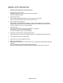
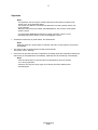
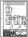
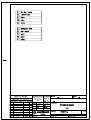
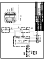
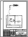
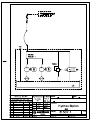
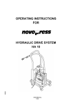
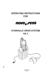
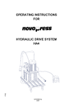
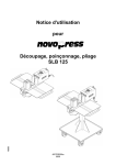
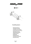
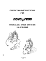
OPERATING INSTRUCTIONS
FOR
16487
HYDRAULIC DRIVE SYSTEMS
HA1ES / HA2
31070\B04eng
0306
Table of contents
Page
CE Conformity Declaration
Safety regulations
Technical data
1
Intended use
2
Construction
2
Connecting system tools
3
Three-phase safety pedal switch
4
Operation
5
Maintenance
6
Appendix: - Circuit diagram
- Hydraulics diagram
31070\B04eng
0306
CE - KONFORMITÄTSERKLÄRUNG
entsprechend EG-Maschinenrichtlinie 98/37/EG, Anhang II A
Novopress GmbH & Co KG
Scharnhorststr. 1
D-41460 Neuss
Hydr. Antriebsaggregat
HA1ES
Ser-nr:
HA2
..............................................
1.
EN 292, EN 294, EN 349, EN ISO 9001, EN 60947-1, EN 60947-4-1
2.
UVV VBG1, UVV VBG4, UVV VBG5, VDE 0100, VDE 0106
Hiermit erklären wir, daß die nachfolgend bezeichnete
Maschine aufgrund Ihrer Konzipierung und Bauart sowie
der von uns in Verkehr gebrachten Ausführung den
einschlägigen grundlegenden Sicherheits- und
Gesundheitsanforderungen entspricht.
Bei einer nicht bestimmungsgemäßen Anwendung der
Maschine oder bei einer nicht mit uns abgestimmten
Änderung der Maschine verliert diese Erklärung ihre
Gültigkeit.
We hereby declare that with respect to its design and
construction the machine stated below and the
model thereof which we have brought into circulation
conform with the applicable basic requirements on
health and safety.
Any use of the machine other than that for which it is
intended and any modification made thereto without
our consent shall render this declaration null and
void.
Angewandte harmonisierte Normen, insbesondere:
Applied harmonized standards, in particular:
siehe Punkt 1
see Item 1 above
Angewandte nationale Normen, insbesondere:
Applied national standards, in particular:
siehe Punkt 2
see Item 2 above
Nous déclarons par la présente que par sa conception
et son type ainsi que par l'exécution que nous avons
mise sur le marché, la machine désignée ci-après
répond aux exigences de sécurité et de prévention de la
santé applicables.
La présente déclaration perd sa validité si la machine
n'est pas utilisée conformément aux instructions ou
dans le cas d'une modification de la machine à laquelle
nous n'avons pas donné notre accord.
Hiermede verklaren wij, dat de hierna genoemde
machine op grond van haar constructie en type
alsmede de door ons in de handel gebrachte
uitvoering aan de desbetreffende fundamentele
eisen ten aanzien van de veiligheid en de
gezondheid voldoet.
Wordt de machine niet overeenkomstig haar
bestemming gebruikt of worden hieraan niet met ons
overeengekomen wijzigingen aangebracht, dan
verliest deze verklaring haar geldigheid.
Normes harmonisées utilisées, en particulier :
voir point 1
Normes nationales utilisées, en particulier :
voir point 2
Toegepaste geharmoniseerde normen, in het
bijzonder:
zie punt 1
Toegepaste nationale normen, in het bijzonder:
zie punt 2
Datum / Herstellerunterschrift:
Angaben zum Unterzeichner:
Formular-Nr: Norm\001NP037.doc
01.04.04
Geschäftsführer
s:\31070\ce\31070c04.doc
Con la presente declaramos que la máquina
denominada a continuación, por su concepto y por su
construcción, cumple con los requisitos
fundamentales de seguridad y sanidad en vigor. Lo
dicho aplica exclusivamente a la máquina en su
versión original, tal y cual ha sido fabricada por
nosotros.
El empleo inapropiado de la misma, así como
cualquier modificación ejecutada sin nuestra
intervención hace que esta declaración pierda su
validez.
Si dichiara che la macchina appresso descritta
soddisfa, per concetto, tipo e modello messo in
commercio, le esigenze di base di sicurezza e sanità
relative a tali apparecchiature.
In caso di uso non appropriato della macchina o in
caso di una sua modifica eseguita senza il nostro
accordo, questa dichiarazione non ha più effetto.
Norme armonizzate applicate, in particolare
vedi punto 1
Norme nazionali applicate, in particolare
Normas armonizadas aplicadas, en particular:
vedi punto 2
véase bajo el punto 1
Normas nacionales aplicadas, en particular:
véase bajo el punto 2.
Härmed försäkrar vi att nedan nämnd maskin
motsvarar de tillämpliga och principiella säkerhetsoch hälsoföreskrifterna både gällande koncipieringen
och konstruktionen samt gällande den av oss sålda
modellen.
Används denna maskin inte enligt anvisningarna eller
förändras maskinen på ett sätt som vi inte har
godkänt, gäller denna försäkran ej.
Täten vakuutamme, että seuraavassa nimetty kone
vastaa suunnittelunsa, rakenteensa sekä meidän
taholtamme liikenteeseen päästetyn mallinsa puolesta
asiaankuuluvia perustavaa laatua olevia turvallisuus- ja
terveysmääräyksiä.
Jos konetta ei käytetä määräysten mukaisesti tai jos
koneeseen tehdään muutos ilman meidän
suostumustamme ei tämä selvitys enää päde.
Tillämpade harmoniserade normer, i synnerhet:
Käytetyt harmonisoidut standardit, varsinkin:
se punkt 1
katso Kohta 1
Tillämpade nationella normer, i synnerhet:
Käytetyt kansalliset standardit, varsinkin:
se punkt 2
katso Kohta 2
Herved erklærer vi at den i det følgende betegnede
maskinen på grunn av dens konsipering og
konstruksjon samt utførelsen som vi har brakt på
markedet tilsvarer de respektive grunnleggende krav
til sikkerhet og helse.
Ved en bruk av maskinen som ikke er formålstjenlig
eller ved en endring av maskinen som ikke er avstemt
med oss mister denne erklæringen sin gyldighet.
Declaramos pelo presente, que a máquina a seguir
designada, na sua planificação e construção, assim
como no modelo por nós comercializado, obedece às
respectivas exigências fundamentais de segurança e
de saúde.
A presente declaração perde a validade em caso de
uso impróprio da máquina ou em caso de modificações
na máquina, que não tenham sido acordadas
antecipadamente connosco.
Benyttede harmoniserte standarder, særlig:
se punkt 1
Normas harmonizadas aplicadas, especialmente:
Benyttede nasjonale standarder, særlig:
vide parágrafo 1
se punkt 2
Normas nacionais aplicadas, especialmente:
vide parágrafo 2
Formular-Nr: Norm\001NP037.doc
s:\31070\ce\31070c04.doc
GENERAL SAFETY REGULATIONS
Read all safety regulations and instructions!
1.
Keep the place of work clean.
Disorderly work-places and work-benches invite accidents.
Ensure that lighting is good.
2.
Keep children away.
Do not allow unauthorised persons to touch the device or the cable.
Keep unauthorised persons away from your place of work.
3.
Wear suitable working clothing.
Do not wear any wide clothes nor jewellery - they may get caught up in moving parts.
When working in the open it is recommended that you wear rubber gloves and non-slip
footwear. Wear a hair- net if you have long hair.
4.
Always be alert.
Only use a device after having been instructed in its operation.
Concentrate on your work. Proceed sensibly.
Do not use the device when you are distracted.
5.
Do not lean too far forward. Avoid abnormal stance.
Make sure that you have a secure standing position, and maintain balance at all times.
6.
Leave safety devices where they belong.
7.
Hand tools may not be installed as fixtures.
8.
Repair and maintenance.
Have repairs and maintenance work carried out in an authorised NOVOPRESS specialist
workshop.
Only use original and identical NOVOPRESS spare parts.
We reject all responsibility and liability for work carried out by third- party personnel.
009NP004.DOC
SAFETY INSTRUCTIONS FOR HYDRAULIC EQUIPMENT
1.
Please read the operating instructions.
Acquaint yourself with the hydraulic equipment.
2.
Provide the equipment with the necessary care.
Always keep the equipment in operational condition.
Cleanness is an essential requirement for good and safe working.
3.
Switch off the electric power supply to the hydraulic equipment,
• when the equipment is not in use
• when maintenance work is to be carried out.
4.
Avoid unintentional switching - on.
Keep hands and feet away from the switch when the equipment is not being used.
5.
Do not use the equipment in a manner in contravention of the instructions.
Never carry the equipment by the pipe or pull on the pipe.
Protect the piping from heat, oil, sharp edges and high levels of weight strain.
6.
Use only piping, fittings and accessories wich have been designed for the operating pressure of
the hydraulic unit.
BURSTING PRESSURE OR TEST PRESSURE IS NOT OPERATING PRESSURE!
Avoid squashing or bending of the piping.
Piping must not be painted over.
7.
Replace the hydraulic piping
• when cracks, squashed or bent points are to be seen
• when blistering is established
• when hydraulic fluid escapes
• when pipe fittings are damaged
• when discolouration is established on the outer layer,
e.g. due to the influence of solvents.
8.
The hydraulic fluid used in the system is kerosene-based.
This requires particular care and attention.
• Avoid continuous contact with the skin
• ensure that the hydraulic fluid does not get into the eyes or mouth.
Hydraulic pipes have to be replaced after 5 years of usage, despite of the circumstance that no
damages should be remarkable.
9.
The equipment must not be operated, if it has leaks and there is a danger of hydraulic fluid
coming into contact with persons, open fire, heating equipment, electric cabling, ground water,
foods and other substances which are intended for human consumption.
10. Hydraulic units with petrol engines
• must not be operated in closed rooms, due to the
DANGER OF INTOXICATION!
• do not pour in petrol while the motor is running or in the vicinity of open fire.
DANGER OF EXPLOSION!
009NP006.DOC
SAFETY TIPS FOR ELECTRIC TOOLS
ATTENTION: In order to avoid electric shock, danger of injury and burning the following
basic safety measures are always to be taken when using electric tools.
Read and observe the notes before using the device. Keep the safety tips in
a safe place.
1.
Take influences of the surroundings into account.
Do not expose electric devices to rain.
Do not use electric devices in damp or wet surroundings.
Do not use electric devices in the vicinity of flammable liquids or gases.
2.
Protect yourself from electric shock.
Do not fix additional rating plates or symbols with rivets or screws.
Use adhesive signs. When working with electric devices avoid
body contact with earthed objects such as pipes, heating appliances, refrigerators etc.
3.
Use the correct tools.
Only use the tools and accessories outlined in the operating instructions.
Do not use the electric device to do work for which it is not intended.
4.
Secure the work piece.
Use gripping devices or vice grips to hold the work piece steady.
It is more securely held than by hand and you can operate the device with two hands.
5.
Do not overload your electric device.
You can work better and more securely in the indicated power range.
6.
Do not use the cable for purposes for which it is not intended.
Do not carry the electric device by the cable.
Do not use the cable in order to pull the plug out of the socket. Protect the cable from heat, oil,
acids and sharp edges.
For working in wet rooms or in the open only use the authorised extension cables with the
corresponding marking.
7.
Avoid unintentional starting.
Ensure that the electric device is switched off before connecting the mains plug.
Do not carry the electric device in such a way as that your finger is on the switch.
Do not use the electric device if the ON/OFF switch does not work perfectly.
8.
Disconnect the mains plug:
• if the device is not in use
• before maintenance of the electric device
• when changing tools
9.
Carefully maintain the electric device. The best and most secure work is guaranteed if you:
• keep the electric device clean
• observe the instructions for greasing, changing the tools and ancillary equipment
• regularly check the connection cable and the extension cable
• have damaged cables repaired by a specialist
• keep hand grips dry, clean and free form oil and fat
• have the electric device examined and cleaned by a specialist after 900 operating hours.
009NP005.DOC
10. Keep electric devices in a safe place.
Store electric tools and accessories out of the reach of children, in dry, high-lying places or in
locked rooms.
11. Electric devices are often used by more than one person. Therefore before beginning to work
you should check:
• the socket to ensure it is securely fixed and is not damaged in such a way as can be
seen from the outside
• the connection cable for outward damage to the insulation and for sharp kinks
• that the cable is securely fixed to the device and whether the insulating plastic tube is
damaged
• that the switch is secure and shows no outward signs of damage
• whether protective appliances or damaged parts function properly
• whether movable parts jam or are damaged
• do not use the device in the event of finding defects
• only allow the device to be repaired by a specialist or in an authorised NOVOPRESS
specialist work-shop
• only use original and identical NOVOPRESS spare parts.
009NP005.DOC
1
Technical data
Electric motor:
Connection voltage:
See identification plate
Power consumption:
800 W
Rotational speed:
max. 10000 min-1
Mode of operation:
S 3; 25 % 100 s
Protection class:
1
Mode of protection:
IP - 44
Radio interference:
As per VDE 0875
Power connection:
Cable, 5 m long, with a three-phase safety
pedal switch and earthing contact-type plug
Hydraulics:
Hydraulic connection:
Quick-action coupling plug with back-pressure valve
Operating pressure:
150 bars max.
Delivery capacity:
at n = 1000 min-1:
Dimensions:
HA 1 ES:
HA 2:
H = 470 mm;
H = 470 mm;
Weight incl. oil:
HA 1 ES:
HA 2:
18 kg
34 kg
Hydraulic oil:
Oil filled in at works:
ISO VG 10 DIN 51519
(suitable for external temperatures from-5 to +35 °C)
HA 1 = 0.45 l/min
HA 2 = 0,9 l/min
B = 250 mm;
B = 280 mm;
Oil usable:
Oil in viscosity class:
ISO VG DIN 51519 from 10 to 46
(viscosity in CSt 7.4 - 30 at 50 °C)
Oil for temperatures < - 5 °C:
ISO VG 5 DIN 51519
31070\B04eng
0306
L = 280 mm
L = 460 mm
2
Hydraulic control units (basic equipment)
With respect to the hydraulic control units there are the following versions:
1.
HA 1 ES
Order No. 31070
Hydraulic control unit with 1 electric motor
2.
HA 2
Order No. 31375
Hydraulic control unit with 2 electric motors
Intended use
NOVOPRESS hydraulic control units operate in the low-pressure range up to 150 bars, and they are
used as drive units for our hydraulic system tools.
The hydraulic unit may only be used with Novopress system tools which have been approved for this
unit (see operating manual for the system tool).
Construction
An oil-filling screw with breather valve (3) and an oil gauge (4) are mounted on the oil tank cover.
Oil gauge (4):
The gauge stick of the oil gauge must be between the two markings. If the gauge stick is at the lowest
marking, oil needs to be added.
Bleeding valve (3):
The air-relief valve closes if the tank is on the slant (no oil can emerge).
In the vertical position (operating position), a slight amount of oil vapour may be carried over with the
escaping air. The oil film which this causes on hydraulic equipment should be removed from time to
time.
Note:
The equipment must not be switched on while horizontal. There is a risk
that the pump will not draw in oil and is damaged as a result.
31070\B04eng
0306
3
Connecting system tools
The system tools are connected to the hydraulic control unit by means of the control line (1) and the
hydraulic hose (2), using the quick-action coupling.
Connecting the hydraulic line
Quick-action coupling
Coupling-up
Hold the coupling socket (KM) up to the sliding sleeve
(SH), and slide it onto the coupling plug (KS).
Uncoupling
Hold the coupling socket (KM) at the sliding sleeve
(SH) and pull it of the coupling plug (KS).
Note:
- When changing the system tools, a small amount of oil will remain between the
back-pressure valves of the coupling.
- Handle the hydraulic hose with care. Bends at the connection points will lead to
premature breakdown. When coupling up, make sure that dirt does not penetrates the
coupling.
- Before coupling up another system tool, wipe out the coupling socket with a clean cloth that is free of fluff.
- The system tools should, as far as possible, remain coupled up at all times.
Connecting electrical leads
HA 1 ES
• Connect the control line (1) of the hydraulic control unit (HA 1 ES) to the system tool with the aid of
the plug connector (5).
HA 1 ES + HA 2
• Connect the mains cable to the power suply line.
Note:
Observe the mains voltage (see identification plate)!
31070\B04eng
0306
4
Three-phase safety pedal switch
1.
2.
3.
1. Pedal not actuated
System tool "OFF"
2. Pedal actuated as far as detectable stop of pressure point
System tool "ON"
3. Pedal actuated beyond pressure point
"EMERGENCY OFF"
Pedal switch locked.
Note!
When EMERGENCY OFF is actuated:
-The hydraulic control unit is switched off and cannot be restarted by pressing the pedal again.
-To release the system, press the blue pushbutton (6).
31070\B04eng
0306
5
Operation
Note!
- The hydraulic unit can only be actuated with the manual button (located on the
system tool), or by the pedal switch.
The system tool which is connected will determine how the hydraulic device has
to be operated.
When the manual key is actuated, the EMERGENCY OFF function of the pedal
switch is active.
- The equipment must not be switched on while horizontal. There is a risk
that the pump will not draw in oil and is damagedas a result.
• Actuate the manual key or pedal switch, and hold it down.
Note!
When the manual or pedal switch is released, the piston of the system tool will return
immediately.
• The piston of the conected system tool will travel forwards.
The system tool is "working".
• Once the work process has been completed or the safety valve has responded, release the
manual key or the pedal switch immediately. Otherwise the oil will heat up unnecessarily.
Note!
- Care should be taken to ensure that the oil temperature does not exceed
70 °C during operation.
- Pressure can only be built up again once the key has been released and
actuated again.
31070\B04eng
0306
6
Maintenance
We recommend that our authorized NOVOPRESS specialist workshops be used for repair and
maintenance work.
Only have the equipment maintained by a specialist.
Caution!
BEFORE ANY MAINTENANCE OR REPAIR WORK,
ALWAYS PULL OUT THE MAINS PLUG!
Check oil level
The gauge stick of the oil level indicator (4) must be between the two markings.
If it is at the lowest marking, oil must be added.
Top up the oil if necessary.
Oil change
First oil change:After about 1,000 starts, or after 3 months
Other oil changes:
After every 15,000 starts, but at least once annually
Oil volume for:
HA1 ES
HA 2
3.5 litres
6.5 litres
Hydraulic oil:
See Technical Data
Oil filter:
The oil filter is the suction strainer with a mesh width
of 0.06 mm.
• Unscrew the oil filling screw with the air-relief valve (3) on the oil tank cover.
• Draw off the old oil by means of suction.
• Fill with new oil.
Note!
The gauge stick of the oil level oil gauge (4) must be between the two markings.
Cleaning:
Remove the oil film from the hydraulic unit every month.
Hydraulic hose:
The hydraulic hose is to be checked for damage every month.
Replace hydraulic hose:
- If any cracks, crush points, or kinks are visible on the outer layer
- If blister formation is visible
- If pressurised fluid is escaping
- If the hose armature is damaged
- If any discolouration of the outer layer is visible,
e.g. due to the effect of solvents.
Hydraulic hoses must be replaced after 5 years, even if no
damage is visible.
31070\B04eng
0306
7
Visual and electrical inspection
Regularly:
Check mains cable including plug and extension cord with plug connectors for
visible damage and have repaired, if necessary.
Every 6 months:
Have an inspection complying with DIN VDE 0701-1 and
DIN VDE 0702 for electric devices of the protection class 1 carried out by a
qualified technician, an authorized workshop or Novopress Neuss.
Hydraulic drive unit H A 1 E S
Legend:
1 = Control line
2 = Hydraulic hose
3 = Air-relief valve
4 = Oil gauge
5 = Plug-in connector
6 = Pushbutton
7 = Pedal switch
31070\B04eng
0306
Repairs / Service
Scharnhorststraße 1
D-41460 Neuss
Federal Republic of Germany
PO Box
101163
D-41411 Neuss
Tel.
02131 / 2880
Telefax 02131 / 28855