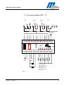
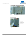
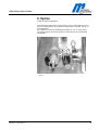
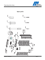
1
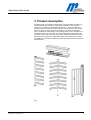
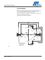
Operating Instructions
Operating Instructions
Pedestrian Turnstile
Type MPT 33
Contents
1. Delivery ........................................................2
2. Safety...........................................................2
3
Description and operation ............................3
4. Foundation ................................................4-5
5. Assembly and installation..........................6-9
6. Electrical connection .............................10-11
7. Access control devices............................... 12
8. Options....................................................... 13
9. Commissioning........................................... 14
10. Technical support....................................... 14
11. Spare parts and accessories.................14-15
12. Warranty .................................................... 16
13. Controler MSC 10....................
581E,5811 10.03_MPT 33
......... 20-22
1
Operating Instructions
1. Delivery
The Security Turnstile consists of:
1 x Semi cage made of stainless steel or mild steel
1 x Center column 3 x 120°, stainless steel or mild steel
1 x Top housing with locking unit
1 x U-bar locking unit
1 x Electronic controller MSC10
1 x Set of documents inside the lockable top cover
1 x Fixing achors (in Europe only)
2 x Keys for the top cover
Technical Data:
Typ
MPT 33
Protection
Voltage VAC
Frequency
Current
Duty Cycle
Weight
Height
Diameter
IP
54
230
50
2,5
100
320
2230
1300
Hz
A
%
Kg
mm
mm
2. Safety
2.1 General safety notes
The Magnetic pedestrian turnstile has been designed, built and tested
according to the latest technology. Although it has left the factory in a fully
operational and safe condition, it is important that the installation is carried out
correctly therefore the operating instructions must be read carefully and the
safety notes must be observed.
Any liability and warranty is declined by the manufacturer in the case of
incorrect use and use for purposes other than intended.
2.2 Use for the intended purpose
The Magnetic pedestrian turnstile may be used only to control pedestrians
entering or exiting restricted areas, usually under surveillance.
The Magnetic Universal Controller may be used only for controlling the
Magnetic pedestrian turnstile. Any other use is not permitted.
Conversions and modifications to the turnstile or to the control modules are
not permitted.
Only original spare parts and accessories from Magnetic may be used.
581E,5811 10.03_MPT 33
2
Operating Instructions
2.3 Identification of risks
Possible risks and notes are identified with the following symbols in the
operating instructions:
Warning!
This symbol in the operating instructions identifies actions and conditions
which can give rise to danger for life and limb of persons.
Observe the instructions carefully.
Caution!
All actions and conditions which can possibly give rise to damage to objects
are identified with this symbol in the operating instructions.
Observe the instructions carefully.
Note!
Relevant and useful notes for the user are identified with this symbol.
2.4 Safety notes
● Disconnect all external opening or closing devices (remote control, control
desk, etc.) during maintenance work
● It is prohibited to install the barrier without proper mounting to the
foundation
● A main power switch or residual current operated device is compulsory
● Risk of bodily harm while cover is open
● Pedestrian barriers are maintenance free
● Documentation should be easily accessible.
● Before commissioning make sure all electrical and functional features are
tested.
● Permissible environmental conditions
● The electrical wiring of the barrier must comply with the included drawings.
● Only certified and trained electrical technicians may perform the electrical
connections
● Only certified and trained electrical technicians may remove covers for
mains plug,mains receivers or wirings
● Before repairing electrical failures disconnect fuse
● Risk of bodily harm if while closing the cover
● During maintenance work the fixing bolt must be checked and tighten, if
necessary.
● Current carrying components like transformers, solenoids, resistors, stator
housings of motors, lamps etc. shall not be touched while in operatingtemperature condition; this can cause skin burns
581E,5811 10.03_MPT 33
3
Operating Instructions
3. Product description
The MPT series of turnstiles are designed to control pedestrians entering or
exiting restricted areas outside in high security situations. The turnstile
consists of four different component parts (see fig. 1) It can be used for bidirectional access control by means of keys or card readers (access control
devices in general). Entry and exit of the barrier can either be operated in
open, controlled or closed modus. The rotating centre column consists of 3 x
120 degreeU bars. The controller, the drive units and the locking device are
mounted on top of the centre unit in a powder coated sheet metal enclosure,
where there is also space for additional access control equipment .Locking
and release of the centre is realized by an electro-mechanical locking device
with solenoids.
Fig.1
581E,5811 10.03_MPT 33
4
Operating Instructions
4. Foundation
A level concrete mounting surface is required to secure the turnstile housing.
For the dimensions please refer to figure 2. The cables should finish a
minimum of 5 meters above the finished concrete surface.
NOTE: This foundation is also required in connection with a foundation frame.
Conduits for mains supply and data lines
should finish 50 mm approx. above foundation
Passage direction
Empty conduit
Empty conduit
bearing
Passage direction
Foundation anchor pin
with inside thread M10
Drilling hole Ǿ 16
Drilling depth 90 mm
Fig. 2
581E,5811 10.03_MPT 33
5
Operating Instructions
Foundation, smoothed finish
to be positioned in water
in a level and horizontal manner
Lay seperate conduits for
power supply and data cables,
50 mm approx. above foundation
All power supply and
data lines are to be 5 m at least
above the empty conduit
After mounting
glue set screw with LOCTITE 241
or similar
Concrete PC 250
with iron reinforcement
empty conduit
O 25 mm
srew
split washer
washer
socket
bearing neck
washer
bearing
Fig.3
581E,5811 10.03_MPT 33
6
Operating Instructions
4.1 Foundation frame
The foundation frame is required for turnstiles to be mounted on a subground,
for example in case of pavers. A level concrete mounting surface is required
for correct mounting of the foundation frame. It should be 150 mm approx.
below the finished surface. Mounting of the foundation frame: correct
positioning of foundation frame, drilling of fixing holes, install fixing bolts, lay
the foundation frame into water by means of jackscrews and tighten the
foundation frame.
Fundamentdübel(F)
Express-Anker M12x153/55 A4
Bohrloch Ǿ12
Bohrtiefe 145 mm incl. U-Profilhöhe
Fig.4
Cable routing from foundation
into turnstile
581E,5811 10.03_MPT 33
Jackscrews
For positioning the foundation
Frame on the concrete, if necessary.
7
Operating Instructions
5. Assembly and installation
5.1 To fit the turnstile (above ground foundation)
• The turnstile should be positioned in its desired location taking care on
which side (right or left) you want part 2 to place for access the system.
This is important in case you want to mount housings for access control
units at part 2.
• Foundation drillings 7 x M16 as per drilling plan figure 2
• Mount threaded rod (see enclosed separate description)
• Wait till bolts are cured (see separate description)
• Mount the components in correct order (part 1, 2..) onto the foundation,
however, do not tighten entirely the bolts in order to compensate any drilling
offset which may occur afterwards. Use screws 6 x M 10 x35. Grease the
screws before.
part 3
part 1
part 2
part 4
Fig.5
•
•
•
•
581E,5811 10.03_MPT 33
Place part 3 upon part 1 and 2. Use screws 8 x M12 x 35 and counternut.
Mount lower bearing (see fig. 8). Using screws M10 x 70. Grease them
before.
Put part 4 on the lower bearing, see fig. 9 and screw it up by means of
4 x M16 x 40 with U-discs and flange. Be sure that the turnstile is in locked
position.
Now tighten all fixing bolts.
8
Operating Instructions
5.2 Fixing on foundation frame
See section 5.1 fixing the foundation.
However in this case the turnstile is mounted on the flanges of the foundation
frame.
Fixing of foundation frame, see section 4.1
5.3 Opening of the top cover
Fig.6
Opening by key. The cover is secured by means of a chain.
Two keys are included in the delivery.
581E,5811 10.03_MPT 33
9
Operating Instructions
5.4 To fit the turnstile (above ground foundation)
Fixing of the turnstile is done by means of the 8 fixing bolts M8 and plain
washer.
After final positioning tighten all bolts firmly.
Note:
1.Mark the dimensions
onto foundation acc. to fig.4
2. Drill
3. Install turnstile
4. screw together (see fig. 5.1
Fig. 7
5.5 To fit the centre column
Fig. 8
581E,5811 10.03_MPT 33
10
Operating Instructions
Fig. 9
Mount the lower bearing on the foundation and stick the centre column on it.
Fig. 10
Fix the centre column by means of the delivered screws M16 at the top
flange.
Make sure the centre is in correct position (centre in locked position).
581E,5811 10.03_MPT 33
11
Operating Instructions
5.6 Assembly of roof with drain
Please see fig. 11.
Fig.11
581E,5811 10.03_MPT 33
12
Operating Instructions
6. Electrical connections
Connection of mains supply should only be performed b y a certified electrian
and According to the connecting diagram or after discussion with the supplier.
Fig. 12
Fig.12
Connection unit with control unit MSC10
Fig.13
581E,5811 10.03_MPT 33
13
Operating Instructions
6.1 Connecting diagram MSC - 10
counter
X17
passage
right
passage
left
X18
X19
X20
X21
X22
X23
X24
alarm
X25
X26 X27
X28
X29
X30
not occupied
K2K
K1K
K3K
K4K
K5K
24V / 400mA
+10%/ -20%
17
18
19
20
21
22
23
24
25 26
27
28
29
30
31
32
MSC
Alarm
ON OFF
RS232
1
2
3
4
5
6
7
8
9
10
11
12
13
14
15
16
n.c.
19VAC
or
24VDC
PE
24V 24V
Sol.
left
Sol.
right
IN1 = opening left
IN2 = opening right
IN3 = emergency release
IN4 = reserve
IN5 = limit switch left
IN6 = limit switch right
IN7 = reserve
FIG.14
581E,5811 10.03_MPT 33
14
Operating Instructions
7. Housings / access control units
Fig.15
Possible adaption of surface control devices
Rear side of the mounting
Lead the cable
from the rear side
of the mounting plate
to the steel tube
and drill the hole.
Here, for example
Fig.16
581E,5811 10.03_MPT 33
15
Operating Instructions
8. Option
Power fail locking mechanism
This mechanism will lock the centre column in one or both directions in the
event of a power failure. This requires changing of the solenoid, see fig. 17,
the components
are available on request ( additional kit for MPT 33, ref. no. 1031,5303).
The centre column can be turned freely in both directions in its standard
configuration.
Fig.17
581E,5811 10.03_MPT 33
16
Operating Instructions
9. Commissioning
Once the mechanical and electrical installation of the turnstile has been
completed, it can be put into service.
Check before startup that all assembly and installation instructions have been
followed and the electrical connections have been performed correctly.
Warning:
Incoming mains supply and
connections should only be
performed by a certified
electrician.
When power is first applied and the isolating circuit breaker is turned on, the
torque drive turns the centre column several times to find the home position
and then locks.
The turnstile is then ready for operation.
Operation of the Turnstile
The Turnstile is generally operated by an access control system or control
switches.
Special control panels are also available for operation.
10. Technical Support
Should faults occur that cannot be rectified by a technician, please contact our
authorised aftersales service representative.
In special cases our Technical Support is available to you: Telephone:
Please refer to the name plate on the turnstile housing for the data required in
the case of queries. This is found under the mechansim cover.
11. Spare parts and accessories
See Figure 14 for the exploded drawing which details the individual parts and
their identification numbers.
581E,5811 10.03_MPT 33
17
Operating Instructions
Spare parts
581E,5811 10.03_MPT 33
Abb.18
18
Operating Instructions
12. Warranty
The manufacturer reserves the right to adapt technological progress without
special announcement. Magnetic will be pleased to provide up to date
information and possible changes or additions to the operating instructions.
Under the precondition that the operating conditions are complied with and no
inadmissible interventions have been made to the interior of the equipment
and the equipment has no mechanical damage, a warranty of 2 year after
delivery of the equipment applies on all mechanical and electrical
components.
581E,5811 10.03_MPT 33
19
Operating Instructions
13. Control Unit MSC 10
Functions
13.1 Functions of digital inputs
Input 1 terminals X21 / X22 = Opening of passage direction left
Opening pulse passage left (entry).
Input 2 terminals X24 / X 25 = Opening of passage direction right
Opening pulse passage right (exit)
Input 3 IN3, terminal 11 = input emergency situation
In case of emergency passage free in both directions.
13.2 Function of semi conductor outputs
Output 1 terminal X6 = solenoid left
Output 2 terminal X7 = solenoid right
Output 3 terminal X8 = reserve
13.3 Function of relay outputs
Relay 1 = counter pulse left terminal X18
If the end position in passage direction left is reached a counter pulse of 300
ms is given. This applies to permanent release also.
Relay 2 = counter pulse right terminal X19
If the end position in passage direction left is reached a counter pulse of 300
ms is given. This applies to permanent release also.
Relay 3 = Display passage free left terminals X22 + X21
In case of free passage left a permanent signal is given. This output can also
be used
to lock a pulse transmitter for passage right if passage left is given free.
Relay 4 = Display passage free right terminals X 24 + 25
In case of free passage right a permanent signal is given. This output can also
be used
to lock a pulse transmitter for passage left if passage right is given free.
Relay 5 = Error-/Alarm output terminal X27
In case of certain errors a permanent signal is given as long as the error is not
eliminated.
Relay 6 = Reserve
13.4 Safety functions
In case of an error in the microcontroller the watchdog function releases a
hardware reset.
581E,5811 10.03_MPT 33
20
Operating Instructions
14. Adjustable parameters
The following parameters can be adjusted by means of DIP switches and
the trimming potentiometer:
DIP
Function
OFF
ON
1
Barrier type
MPT
MPP
2
Pulse storage
Off
3
Locking delay time
Off
On = 4 pulses per
direction
On = 1 sec.approx.
4
Hardware tests
*)
*)
5
Hardware tests
*)
*)
6
Solenoid left
Normal
inverted
7
Solenoid right
Normal
inverted
8
Opening duration via LEDs
No display
display
DIP 1 Selection of barrier type
One of the following barrier types must be selected:
-
MPP
MPT
At present this demand is locked; in every case barrier type MPT is selected.
DIP 2 Pulse storage
In case the function is switched-off the demand pulses from one direction only
can be processed. Demand pulses from the other side are then ignored.
In case the function is switched-on max. 4 demand pulses per passage
direction can be stored.
DIP 3 Locking delay time
In order to avoid a rotation of more than 120° in case of permanent release or
several stored pulses a locking delay time can be activated via a dip switch.
The turnstile is then locked for 1 sec. approx after rotation of 120° and will
then be released for passing.
DIP 6 Solenoids
Via DIP 6 and DIP 7 the function of both solenoids can be inverted separately
for both directions. This depends on whether the solenoids are integrated
currentless open or closed. DIP 6 affect the left solenoid output and DIP 7
the right one.
581E,5811 10.03_MPT 33
21
Operating Instructions
DIP 5 Opening duration
To be adjusted via trimming potentiomenter between 1 – 32 sec..
15. Operating modes
15.1 Pulse operation in both directions without pulse storage
15.2 Pulse operation in both directions with pulse storage
15.3 Permanent release in both directions
15.4 Pulse operation in one direction, permanent release in the other
direction
Recommendations
Recommendation 89/392/EWG of 14.06.89 incl. modifications up to
93/68/EWG of 22.07.03
Recommendation 73/23/EWG of 19.02.73 incl. modifications up to
93/68/EWG of 22.07.03
Recommendation 89/336/EWG of 03.05.89 incl. modifications up to
93/68/EWG of 22.07.03
DIN VDE 0113 T1 06.93 (EN 60204-1-1992, IEC 204-1-1992)
DIN EN 292 T2 11.91
581E,5811 10.03_MPT 33
22