1
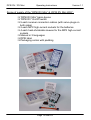
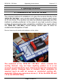
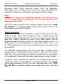
Operating Instructions DPSI RV / RV Mini Operating Instructions Version 1.1 Table of contents 1. Foreword .......................................................................................... 3 2. Features ........................................................................................... 4 3. The “DPSI RV / RV Mini” in bullet points ...................................... 7 3.1. LDO-Versions .......................................................................... 8 3.2. HFIB (High Frequency Interference Blocking) ......................... 9 3.3. APP (Advanced Push Pull Servo Pulse Amplification) ............ 9 3.4. IVM (Intelligent Voltage Monitoring)....................................... 10 3.5. Safety Features of the “DPSI RV / RV Mini“ .......................... 10 4. Packing Contents.......................................................................... 11 5. Operating Information .................................................................. 13 5.1. Installation of the “DPSI RV / RV Mini” .................................. 13 5.2. Connecting the Switch ........................................................... 15 5.3. Connecting the Receiver ....................................................... 18 5.4. Selection of Batteries............................................................. 19 5.5. Soldering the Battery Sockets ............................................... 23 5.6. Charging of the Storage Batteries ......................................... 24 5.7. Setting the Voltage ................................................................ 25 5.8. Programming the Batteries .................................................... 26 5.9. Connecting the Servos .......................................................... 29 5.10. Connecting Additional Products........................................... 32 5.11. Operation ............................................................................. 33 5.12. Error Indicator ..................................................................... 34 6. Safety Instructions........................................................................ 37 7. Technical Data of the “DPSI RV / RV Mini (LDO)”...................... 39 8. Warranty......................................................................................... 41 9. Notizen / Notes .............................................................................. 43 Page 2 from 43 DPSI RV / RV Mini Operating Instructions Version 1.1 1. Foreword The “DPSI RV / RV Mini“ (Dual Power Servo Interface – Regulated Voltage) that you have just acquired is an ultra-modern, electronic product that was developed in Germany by experienced engineers and is manufactured on our own production line. The highest quality, functionality and fail-safe operation were all taken into account in the development of this product. Following the establishment of the DPSI2001 precursor model as the most successful power supply system of its kind throughout the world, we integrated all of the experience gained from this model into the new products including some additional improvements. The wishes of the best RC pilots in the world have been integrated into its development. A costly optical and electronic final inspection of each system that leaves our plant ensures that you, the customer, receive an absolutely dependable product that will considerably increase the operational safety of your valuable RC model. As a matter of course, the “DPSI RV / RV Mini“ was subjected to an intensive flight test in addition to extensive laboratory tests. We thus carried out costly series of tests, for example, with data loggers that were specially developed for measuring the actual power consumption in model airplanes. Carrying out an FMEA analysis (Failure Mode and Effects Analysis), a standard in the automotive industry, reduces to a minimum the possibility of damage and malfunction in the case of faulty operation. We encourage you to read this manual carefully and pay close attention to the installation instructions. This can prevent errors in advance. We welcome your requests and inquiries at any time. Please provide us with the challenge! Bobingen, August 2003 Page 3 from 43 DPSI RV / RV Mini Operating Instructions Version 1.1 2. Features The “DPSI RV / RV Mini“ is used as a redundant power supply and distribution for receivers and servos (steering gear) in RC models. Redundancy is achieved by means of two connected storage batteries. If one battery fails, the second battery ensures reliable operation. In most cases, both storage batteries are discharged simultaneously. In addition, the current of each individual battery is cut in half (for batteries connected in “parallel”), meaning that even cells with a lower level of maximum admissible current can be used. As with the DPSI-2001, all servos directly connected to the “DPSI RV / RV Mini“ are provided with full battery capacity and each servo receives the maximum possible current with no impact on the sensitive receiver. Because the distribution voltage is switched on electronically (the switch does not activate any current, but rather only the switch-on signal), no losses, contact errors or transition resistance occur. This internal electronic switch is fail-safe. Thus, a switched-on “DPSI RV / RV Mini“ remains switched on even if, for example, the On/Off switch is separated or interrupted. The new “DPSI RV / RV Mini“ (Dual Power Servo Interface Regulated Voltage) ensures a previously unattained level of safety for RC receiving stations. Another significant factor to consider is the stabilized output voltage, which supplies both the receiver and the steering gear (servos). Thus, the “DPSI RV / RV Mini“ is the first system worldwide to offer: battery switching function complete constant voltage control for all RC components electronic, fail-safe On/Off switch servo-current distribution with HF anti-jamming intelligent battery monitoring with acoustic warning all in a single housing. Page 4 from 43 DPSI RV / RV Mini Operating Instructions Version 1.1 Up until now the receiving station was supplied directly from the connected batteries (or by a corresponding battery switch). The output voltage of batteries depends largely on the current discharge status. Since 5 NiCd or NiMH cells are almost always used in large models, a fully charged battery reaches up to 7.5 V when the battery charger is switched off (depending on the charging current and internal resistance of the battery) Of course this peak voltage sinks rather quickly to about 6.4 volts (within 5-10 minutes under load), but can result in a shorter service life of the servo in the worst-case scenario, since the manufacturer normally only approves them up to 6 V. The electronics of the “DPSI RV / RV Mini“ then ensures that the voltage of the batteries is limited to a permissible level, regardless of the higher input voltage of the batteries. Jumpers (small links) can be used to adjust the output voltage in 4 stages. In this way the power requirement can be adjusted to the needs of the pilot. In addition, servos that are only approved for 4.8 V can also be used. The main advantage of the constant voltage control in the „DPSI RV / RV Mini“, however, is that now new, future-oriented battery technology that was previously reserved for driving electric motors can also be used. Lithium ion (Lilon) and, in particular, plastic lithium polymer cells (PLi or LiPoly) will replace the previously well-known battery types for the medium term. These new cells have a nominal output voltage of 3.7 V per cell. A series circuit of two cells thus results in a rated voltage of 7.4 V (as much as 8.4 V after charging), which was previously unsuitable for receiver applications. This changes in the case of the “DPSI RV / RV Mini“, which is specially designed for using these cells. The advantages of the lithium polymer cells can be found in their low weight (extremely high energy density), the low level of self-discharge, the capacity to charge quickly and their environmental friendliness. The energy density of the lithium polymer batteries is approximately 400% greater than traditional NiCd cells! Page 5 from 43 DPSI RV / RV Mini Operating Instructions Version 1.1 A micro-controller was integrated into the “DPSI RV / RV Mini“ for the first time in order to notify the user of the charge status of the batteries. The intelligent algorithm enables it to monitor all voltages. Unmistakable error messages (e.g. battery voltage is too low) are acoustically delivered by means of a built-in signal transmitter. Compared to the previous depiction of voltage using light-emitting diodes, direct eye contact with the LEDs is now no longer needed. The “DPSI RV / RV Mini“ also provides the option of connecting external LED displays (battery controllers) directly. The „DPSI RV / RV Mini“ can be adjusted to the type of battery so as to enable the use of different storage batteries. Simple programming allows you to choose between 5, 6, and 7-cell NiCd/NiMH batteries or Longgo batteries (plastic lithium polymer / LiPoly). The „DPSI RV / RV Mini“ is delivered complete. All inputs and outputs are pluggable. This means that a (damaged) cable can be replaced at any time or the length of cable (to the receiver) can be selected as desired. In order to save on superfluous weight, only the amount of cable actually needed is run from the “DPSI RV / RV Mini“ to the receiver. It is a matter of course that the proven characteristics of the DPSI-2001 (a market leader in its field for receiver power supply for large models), is also integrated into the new “DPSI RV / RV Mini“. To allow for various applications, two systems were developed (the DPSI RV and the DPSI RV Mini). The DPSI RV is predestined for large models requiring a large number of servos. Another unique feature of this system is the option of connecting 12 receiver outputs, which are distributed to a total of 32 servos. Mainsail pilots in particular have felt the need for this diversity. The DPSI RV Mini is directed toward pilots in the 2 to 2.5-meter stunt flying class, who do not require as many servos in their models. Therefore the DPSI RV Mini only supplies the heavily impacted rudders (aileron, elevator, and vertical rudder), while the remaining functions (engine, extendable landing gear, etc.) are supplied directly from the receiver. Page 6 from 43 DPSI RV / RV Mini Operating Instructions Version 1.1 3. The “DPSI RV / RV Mini” in bullet points Double power supply with controlled voltage for receiver AND servos Output voltage adjustable in 4 stages from 4.8 V to 6.0 V (per jumper) Compliance with all manufacturer specifications for RC receiving stations Continually constant servo-actuating power from constant power supply Lilon / PLi (LiPoly) Longgo cells can be used 5, 6 and 7-cell NiCd / NiMH batteries can be used Electronic, fail-safe On/Off switch with additional connection option for external LED voltage displays Short circuit-proof servo pulse amplification in power-saving APP technology (Advanced Push Pull) HFIB (High Frequency Interference Blocking), blocking of injected high frequency interference from long servo-cables (separate for each servo) Capable of bearing up to 56 A peak current (14 A for the DPSI RV Mini) 12 receiver channels with current distribution to 32 servoconnections for the DPSI RV 5 receiver channels with current distribution to 8 servoconnections for the DPSI RV Mini IVM (Intelligent Voltage Monitoring) – intelligent voltage monitoring with acoustic status indicator for four different types of batteries (programmable) Cable-free system, i.e. all inlets are pluggable and therefore replaceable at any time Trouble-free operation with two receivers possible Special grounding concept for trouble-free operation and maximum safety. Page 7 from 43 DPSI RV / RV Mini Operating Instructions Version 1.1 A housing of high-quality plastic injection molding with integrated holding clamps for the battery connector plugs and reverse connector protection of the servo-plugs Large-surface cooling elements for deflecting heat loss Each system 100% inspected and provided with a unique serial number Developed and produced by the market leader (Made in Germany) A global innovation – the first system of its kind to date! 3.1. LDO-Versions For users who would like to continue using their previous 5-cell batteries, or users who would prefer to use 5-cell batteries, the “DPSI RV LDO / RV Mini LDO“ is now available. “LDO” stands for “Low Drop Out”, which means lower loss of voltage. By means of a special, ultramodern constant voltage control, losses in the electronic components are so low (only about 0.3 V), that an output voltage of 5.5 or 6.0 V is possible even when using 5-cell batteries. Of course the output voltage naturally drops somewhat with a setting of 6.0 V, if the battery voltage drops below 6.3 V. With a rated battery voltage of 6.0 V, there is still always an output voltage of 5.7 V available. Page 8 from 43 DPSI RV / RV Mini Operating Instructions Version 1.1 3.2. HFIB (High Frequency Interference Blocking) To increase safety, a highly effective T-filter is connected to the existing circuit (looped in) in the signal pathway for every servo of the “DPSI RV / RV Mini“ (32 each for the DPSI-TV and 8 each for the DPSI RV Mini). This is indeed more expensive than the simple filtering of 12 or 5 receiver channels – but it results in the interference being eliminated directly at the servo plug so that it does not pass through the entire circuit board. These filters enable HF interference, which can be “captured” by long servo-cables, to be reduced by up to 90%. Ferrite rings, as previously used, can now be eliminated, which saves on weight and cost. Anti-jamming of the “DPSI RV / RV Mini“ is also considerably more effective than anti-jamming using ferrite rings. Trouble-free operation using digital servos is also possible with these filters. 3.3. APP (Advanced Push Pull Servo Pulse Amplification) In order to optimally prepare the control pulses from the receiver and make them available for each servo, they are electronically amplified. Normally the pulse signal with parallel connection of servos (V-cables) is dampened, making it more susceptible to interference. With the „DSPI-RV / RV Mini“ the pulse is fully maintained on one channel, even when 4 (2) servos are connected. The special feature of pulse amplification is the short-circuit stability against plus and minus. If there is an error in wiring, which short-circuits the stepping line of a servo at the plus or minus pole, the pulse amplifiers are not destroyed and all other servos on this channel can continue to operate troublefree. Another advantage is the power-saving APP technology. The amplifiers have push/pull high-level stages, which actively control both the low and high phase of the servo pulse. This eliminates the high switching current of traditional open collector high-level stages, where the low phase of the servo pulse is generated as a “short-circuit current” by means of a load resistor. Page 9 from 43 DPSI RV / RV Mini Operating Instructions Version 1.1 3.4. IVM (Intelligent Voltage Monitoring) An internal 8-bit micro-controller monitors all voltages using an intelligent algorithm and shows various faults (overload, low voltage, voltage faults) acoustically by means of a built-in piezo buzzer. 3.5. Safety Features of the “DPSI RV / RV Mini“ Short circuits on the servo stepping lines, regardless of whether they are toward the plus or minus of the servo cable, do not result in damage to the “DPSI RV / RV Mini”. All other servos of the channel in which the short circuit occurs remain fully functional. Even if the servo’s polarity is reversed, the “DPSI RV / RV Mini“ is not damaged. A servo cable that is accidentally short-circuited will generally burn out or melt, without damaging the “DPSI RV / RV Mini“ (in the case of thick cable diameters, however, the strip can also be affected, since the „permissible“ current for strips is only about 2-3 A). The cooling elements of the “DPSI RV / RV Mini“ naturally become very hot when this type of short circuit occurs! The decoupling of the two batteries as well as the electronic switches is completely separate (including peripheral electronics) and therefore carried out twice. No double diodes are used (two diodes in one housing). Thus the failure of one component can never lead to the failure of the entire system. The switching mechanism has already proven to be outstanding in several thousand systems (DPSI-2001). The “DPSI RV / RV Mini“ does not need to be separated from the batteries during long breaks (e.g. in winter), since the self-charging of the batteries is considerably greater than the no-signal current consumption of the “DPSI RV / RV Mini“, which is virtually unmeasurable. Page 10 from 43 DPSI RV / RV Mini Operating Instructions Version 1.1 To enable optical switch-on control, an ultra-bright light-emitting diode was installed into the switch of the “DPSI RV / RV Mini“. This signals that the system is turned on, even at great distances. All commercial remote control systems (Graupner JR, Multiplex, Futaba) were successfully tested in all types of modulation (PCM, SPCM, PCM1024, PPM, IPD) in connection with the “DPSI RV / RV Mini“. Thus, all systems can be used trouble-free. The “DPSI RV / RV Mini“ offers the option of connecting a second receiver. Both receivers should be the identical type (the type of modulation must always be the same). Based on the sophisticated safety characteristics from extensive tests, operating errors and external influences do not usually result in damage to the “DPSI RV / RV Mini“. 4. Packing Contents Scope of supply of the “DPSI RV” & „DPSI RV LDO“: “DPSI RV” basic device “DPSI RV” On/Off switch 12 each receiver connection cables (with servo-plugs on both sides) 2 each MPX high-current sockets for the batteries 4 each heat-shrinkable sleeves for the MPX high-current sockets Manual in 3 languages DPSI label Packaging carton with padding Page 11 from 43 DPSI RV / RV Mini Operating Instructions Version 1.1 Scope of supply of the “DPSI RV Mini” & „DPSI RV Mini LDO“: “DPSI RV Mini” basic device “DPSI RV” On/Off switch 5 each receiver connection cables (with servo-plugs on both sides) 2 each MPX high-current sockets for the batteries 4 each heat-shrinkable sleeves for the MPX high-current sockets Manual in 3 languages DPSI label Packaging carton with padding Page 12 from 43 DPSI RV / RV Mini Operating Instructions Version 1.1 5. Operating Information 5.1. Installation of the “DPSI RV / RV Mini” The simplest method of installation is to glue the receiver directly to the “DPSI RV / RV Mini“ using double-sided adhesive cellular rubber strips (5-10 mm thick). The receiver can also be attached separately and this method is actually preferred. In the case of very high current (a large number of servos) and under competitive conditions, the upper side of the “DPSI RV / RV Mini“ should always remain open to allow for unobstructed dissipation of heat. Receiver fastening with double-sided adhesive cellular rubber: The underside of the “DPSI RV / RV Mini“, which contains the cooling element, may not have anything pasted on it or be covered up and should be at an interval of at least 30 mm from the nearest surface (fuselage floor or similar)! Good ventilation is required (such as with air scoops or conducted cooling air), especially if there are numerous servos (> 16 for the DPSI RV and > 8 for the DPSI RV Mini). Page 13 from 43 DPSI RV / RV Mini Operating Instructions Version 1.1 Since the “DPSI RV” is most often used in large models, it is advisable to fasten the entire package with rubber bands on 4 sides, oscillating freely in the fuselage (see photo). Bracing the DPSI RV with rubber bands: The “DPSI RV Mini” was developed for smaller models, which are narrower. Fastening onto 4 silicone hose pieces has proven to work well in this case. Thus the entire package is fastened to 4 “stilts”, with vibration reduction, as shown in the photo. This method of fastening is of course possible with the “DPSI RV” as well. Page 14 from 43 DPSI RV / RV Mini Operating Instructions Version 1.1 As a general rule, your must always ensure that the fastening is as vibration-free as possible and has sufficient air circulation. Reduction of vibration is particularly important for the receiver, since it reacts far more sensitively to mechanical vibrations than the “DPSI RV / RV Mini”. Hole spacing for fastening: 67,7 mm DPSI-RV Mini DPSI-RV 75,7 mm 152,3 mm 78,7 mm 5.2. Connecting the Switch Mechanical switches contain the risk of failure. In large models, vibrations at the fuselage side are quite high. Thus rocker switches failures, for example, have already been observed. In order to rule out any possible mechanical influence, the “DPSI RV / RV Mini“ includes a pin for switching the receiver station on or off. The pin is a gold-plated 2mm plug pin, which when plugged into the “On” socket (red), switches on the “DPSI RV / RV Mini“ and when plugged into the „Off“ socket (black), switches it off. Many tests (a qualification test in an environmental lab, among others) proved that the pin could not be lost due to vibrations. Even if the pin should get lost, the „DPSI RV / RV Mini“ remains switched on (in switched-on mode). The „DPSI RV / RV Mini“ can only be switched off if the pin plug is plugged into the off socket. Of course a pin plug may not be plugged into every socket, even though this does not damage the “DPSI RV / RV Mini“. In this case, the “DPSI RV / RV Mini“ would be switched off and the batteries would slowly discharge with approx. 12mA. Page 15 from 43 DPSI RV / RV Mini Operating Instructions Version 1.1 The contact pin should always remain plugged into the On-socket when operation is “on”! If the pin should get lost, a 2 mm wire or a 2 mm screw can be used; simply plug it into the respective pin socket. The On/Off switch can be placed wherever desired (e.g. on a fuselage side wall). A drilling jig for the switch is included with these instructions. The connection cable with plug is plugged into the respective multiple plug of the “DPSI RV / RV Mini“ until it locks into place on impact (see photo). In the event that replacement or removal is necessary, the plug can be disengaged from the multiple plug by carefully pulling it out parallel (take hold of the cable directly at the plug). A switch correctly mounted on the DPSI RV: Page 16 from 43 DPSI RV / RV Mini Operating Instructions Version 1.1 DPSI RV switch: The central, ultra-bright light-emitting diode (LED) in the switch always illuminates when the „DPSI RV / RV Mini“ is switched on (pin plug in the red On-socket). Two commercial battery controllers can be plugged directly to the backside of the switch. The inscription “B1” stands for battery 1, and “B2” for battery 2. This enables additional optical voltage monitoring of the batteries. When using this type of battery controller, you must ensure that the required number of cells is correctly set. If the pin plug is plugged into the black (off) socket, the entire receiver station is switched off (any battery controllers that may be connected as well). In switched-off position, the storage batteries will not discharge. The minimum “no-signal current” of the „DPSI RV / RV Mini“ is far below the self-discharge of the connected batteries. Theoretically, it would take 274 years for the no-signal current to discharge a battery with 2.4 Ah. Page 17 from 43 DPSI RV / RV Mini Operating Instructions Version 1.1 5.3. Connecting the Receiver Not all of the 12 or 5 inputs of the „DPSI RV / RV Mini“ need be contacted when connecting the receiver. In both cases the supplied cable is sufficient for all DPSI inputs – however, only the number of cables (channels) required should be plugged in. This saves on weight and cabling expense. All receiver connecting cables supply the receiver with the controlled rated voltage. It therefore does not make any difference which cable (which channel) is connected. In the case of the “DPSI RV Mini“, it is important that the plug be correctly connected, since the servo and receiver connections are located on a multipoint connector. Receiver connection on the DPSI RV Mini: If two receivers are to be used, this is likewise feasible. The connection cables desired in each case are then connected to the receiver at which they are needed. Page 18 from 43 DPSI RV / RV Mini Operating Instructions Version 1.1 Two receivers on the DPSI RV: Servos can be connected directly to the receiver for both the “DPSI RV“ and the”„DPSI RV Mini“. This only makes sense for the “DPSI RV Mini“, however, since it only has 5 channels available (distribution to 8 servos). When all components of the receiver station (receivers and servos) have been supplied with the same controlled voltage, the regulating speed of all servos also remains the same (so they are of the same type). 5.4. Selection of Batteries Regular commercial batteries can be considered for use as batteries (NiCd and NiMH), but lithium-ion, lithium-polymer and in particular our “Longgo” batteries may also be used. The number of cells of the storage batteries being used complies with the output voltage. The control electronics in the „DPSI RV / RV Mini“ results by principle in a loss voltage, which is converted to heat. This loss voltage must be added to the selected output voltage. The following values can be used as an empirical formula for the number of cells to be selected: Page 19 from 43 DPSI RV / RV Mini Operating Instructions Version 1.1 DPSI RV / RV Mini Output voltage 4.8 V 5.2 V 5.5 V 6.0 V Number of cells NiCd/NiMH 5 or 6 6 6 6 or 7 Longgo battery Well-suited Very well-suited Very well-suited Well-suited In the case of a servo-current of 4A, the dropout loss is approx. 1.40 V For applications for which only 5 cells (NiCd or NiMH) should be used, but an output voltage of 4.8 V is too low, the “DPSI RV LDO / RV Mini LDO“ can be used as an alternative. “LDO” stands for LowDropOut (low loss of voltage). By means of a special voltage regulator, the loss of voltage is considerably reduced, so that even when using 5-cell batteries it is possible to have an output voltage of 5.5 V or 6.0 V. DPSI RV LDO / RV Mini LDO Output voltage 4.8 V 5.2 V 5.5 V 6.0 V Number of cells NiCd/NiMH 5 5 5 5 or 6 Longgo battery Well-suited Very well-suited Very well-suited Very well-suited In the case of a servo-current of 4A, the dropout loss is approx. 0.3 V We recommend a voltage of 5.5 V as supply voltage for the entire receiver system (also for servos that are approved up to 6 V). The leeway up to the 6.0 V - limit should not be utilized. The servos are barely any faster at 6.0 V, while consumption and wear are both higher. Page 20 from 43 DPSI RV / RV Mini Operating Instructions Version 1.1 Especially when using electronic aides (such as MagicBox, gyroscopes, etc.), it is better to use “only” 5.5 V, since almost all semiconductors (and micro-controllers) “cope better” with this voltage. Note: The output voltage of the “DPSI RV / RV Mini” should only be set to 5.5 V even with 6 V servos (for 4.8 V servos to 4.8 V or a maximum of 5.2 volts). Due to the dropout losses in the constant voltage control of the “DPSI RV / RV Mini“, it is definitely NOT possible and not permissible to use 4-cell battery packs (NiCd / NiMH)! Battery capacities In general, the maximum admissible current and the capacity of the batteries being used must be observed. Thus, 2 battery packs with 450mAh for a 3m model with, say, 15 servos, would be far too small. At least two “2000’s” should be used in this case, which can be discharged with 6C (peak current). (C is the rated capacity in Ah => a battery with 2.0 Ah can therefore be loaded at 6 C with 6 * 2.0 A = 12 A). When digital servos are used, increased power consumption can be assumed. Our elaborate measurements of a 3m model with 15 digital servos showed a power consumption of about 0.6 Ah – 0.8 Ah for a 10-minute flight time. You must therefore proceed very carefully when calculating for the batteries! Check with the model manufacturer in case of doubt. In addition, when selecting the batteries, you should ensure that the connection cables for the batteries are sufficiently thick. If a battery with a cable diameter of 0.25mm2 is used, the advantage of the “DPSI RV / RV Mini“ is partially negated, since losses will occur in the thin cable. Page 21 from 43 DPSI RV / RV Mini Operating Instructions Version 1.1 The following calculation applies: A highly flexible copper cable with a diameter of 0.25 mm2 and a length of about 25 cm has a resistance (back and forth) of about 0.05 Ohm. The power handling capacity of this type of cable is at a maximum of 2.5 A. With a theoretical current of 10 A, the drop in voltage in this cable is already 0.5 V. Instead of 6.0 V reaching the „DPSI RV / RV Mini“, for example, there are now only 5.5 V. The battery lines for the 3 m models should therefore have a diameter of 1.0 – 1.5 mm2. The battery connection cables must be soldered to the included Multiplex high-current pin-and-socket connectors so that they are compatible with the “DPSI RV / RV Mini“. A heat-shrinkable sleeve for insulating the soldered connections is also included. If, due to center of gravity, the batteries are placed far away from the “DPSI RV / RV Mini“ (the connection cable is therefore quite long), it is advisable to twist the cable of the storage batteries. We recommend using our Longgo cells. These are supplied completely cabled and can be attached immediately to the “DPSI RV / RV Mini“. An additional charging cable enables charging without having to disconnect the battery from the “DPSI RV / RV Mini“. Loading devices for the Longgo cells are also available from EMCOTEC. Page 22 from 43 DPSI RV / RV Mini Operating Instructions Version 1.1 5.5. Soldering the Battery Sockets The included Multiplex high-current sockets are marked + and – on the solder side. It is imperative to observe this marking! The cable is first stripped about 5 mm and then tin-plated. Before soldering to the socket, the included heat-shrinkable sleeve must be pushed over the respective cable. During soldering the cable is then soldered to all 3 connecting pins of one side of the socket, so that it comes to rest in the middle of the 3 small legs (see sketch). When using thin cables, the connecting pins of the socket can be bent somewhat toward the middle. Plenty of solder should be used to ensure good contact with all of the contacts. The heat-shrinkable sleeve is now shrunk using a hot air dryer. Soldering the Multiplex socket: Note: The „DPSI RV / RV Mini“ is not reverse polarity protected due to type of construction! Please ensure that the batteries are always correctly connected, i.e. the red line must always be at the plus and the black line always at the minus. It is better to check one time too many than not enough times! Page 23 from 43 DPSI RV / RV Mini Operating Instructions Version 1.1 5.6. Charging of the Storage Batteries The „DPSI RV / RV Mini“ operates with battery plus, i.e., the two batteries are connected to the minus (ground), as long as they are connected to the “DPSI RV / RV Mini“. In order to enable charging of the battery, even if it is connected to the “DPSI RV / RV Mini”, a second cable must be soldered to the battery, or the battery must be connected by means of a V-cable. If using a second or V-cable, you must observe how the charging device is working if both (attached) batteries are to be charged at the same time. The simultaneous charging of both batteries is not always possible. Separate charging of the batteries using a V-cable is possible at any time, however! In case of doubt, it is therefore practical and safer to detach the batteries from the “DPSI RV / RV Mini“ for charging. To do so, pull the plug from the holding clamps of the “DPSI RV / RV Mini” in zigzag movements and slightly tilted (to the side). Removing the battery plug on the DPSI RV / RV Mini: Page 24 from 43 DPSI RV / RV Mini Operating Instructions Version 1.1 Note: The battery can be charged (e.g. using a V-cable) when it is attached to the “DPSI RV / RV Mini”. But only one battery should be charged at a time and not both batteries at the same time. Please observe the correct polarity at all times! 5.7. Setting the Voltage The output voltage of the “DPSI RV / RV Mini“ can be set in 4 stages for receivers and servos. This is done using the provided jumpers, which – depending on the output voltage - are coded and plugged to the strips of the “DPSI RV / RV Mini”. It is best to use tweezers or a small pincer for this purpose. A small strip of adhesive tape (Tesa or the like) protects the jumper from slipping out. If the “DPSI RV / RV Mini“ has been attached so as to be free of oscillation, the jumpers generally cannot fall out. Setting the voltage of the “DPSI RV Mini ” to 5.5 volts: The jumper position is printed on the housing of each DPSI RV. Page 25 from 43 DPSI RV / RV Mini Operating Instructions Version 1.1 Note: We recommend 6-cell battery packs or our Longgo batteries, with the voltage being set to 5.5 V (when using 6 V servos). We recommend 5-cell batteries for the “DPSI RV LDO / RV Mini LDO“. 5.8. Programming the Batteries Since the “DPSI RV / RV Mini“ has intelligent battery voltage monitoring, the battery type being used must be communicated to it (whether 5, 6 or 7-cell batteries or Longgo batteries are being used, for example). The type of battery only needs to be programmed one time – the programmed status then remains saved in the microcontroller of the „DPSI RV / RV Mini“ until eventually replaced by a new program. Programming starts up when only one battery (regardless of which type and to which battery connection) is connected to the “DPSI RV / RV Mini“ and when the latter is turned on. After it is turned on, the internal buzzer (signal transmitter) of the “DPSI RV / RV Mini“ switches on for three seconds, to then insert a pause of three seconds. This displays the operating mode “programming”. Following this is a one-time beep, which displays “Battery type No. 1”. If, at this point, the missing battery is connected to the “DPSI RV / RV Mini“ within three seconds, this „Battery Type No. 1“ is selected and will be programmed. If the missing battery is not attached within the three seconds, a two beeps for “Battery type No. 2” are emitted. Here again the user has three seconds to attach the missing battery, if he wishes to select (program) this type. This principle is repeated until the buzzer has beeped five times (deactivate all tests). If the missing battery is not attached within three seconds, no programming is done and the system changes to the normal operating mode. Page 26 from 43 DPSI RV / RV Mini Operating Instructions Version 1.1 The types of batteries are defined as follows: Buzzer code 1 beep 2 beeps 3 beeps 4 beeps 5 beeps Type of battery / programming 5 cell battery (NiCd / NiMH) 6 cell battery (NiCd / NiMH) 7 cell battery (NiCd / NiMH) Longgo battery (PLi or LiPoly) Deactivate all tests At delivery, “Battery type No. 4” (the Longgo battery) is programmed by default. When “5 beeps” is selected (all tests deactivated), the “DPSI RV / RV Mini“ does not carry out any voltage tests. Therefore, no empty batteries or other faults are acoustically notified. Note: Two identical batteries must be used at all times (i.e. the same battery type (NiCd, NiMH or Longgo) with the same number of cells. The battery capacity may vary, on the other hand (even if this is not practical). Page 27 from 43 DPSI RV / RV Mini Operating Instructions An overview of programming the type of battery: Page 28 from 43 Version 1.1 DPSI RV / RV Mini Operating Instructions Version 1.1 5.9. Connecting the Servos The “DPSI RV” distributes 12 servo outlets of the receiver on a total of 32 servo connections. The “DPSI RV Mini” distributes 5 servo outlets of the receiver on a total of 8 servo connections. For this purpose, a distribution that enables a number of combinations has been selected. The following examples using a Graupner JR system should clarify the connection scheme. Of course the servo arrangement as well as the receiver arrangement can be adjusted according to individual concepts or needs. Connection scheme of the “DPSI RV”: Receiver Channel DPSI RV Number of Servos Function (JR) Example model 1 2 Throttle 1 Servo 2 4 Aileron left 3 Servos 3 4 Elevetor left 2 Servos 4 4 Rudder 4 Servos 5 4 Aileron right 3 Servos 6 4 Elevetor right 2 Servos 7 4 Free --- 8 2 Smoke 1 Servo 9 1 Choke 1 Servo 10 1 Free --- 11 1 Free --- 12 1 Free --- In this example, a total of 17 servos are connected to the „DPSI RV“. For all servos, the pulse cable is at the bottom (as specified by the plug-in direction (beveled nose) of the housing). If two or more servos are soldered directly together in the respective rudder and run to the “DPSI RV” with one cable, then this cable must carry the current of both servos, which can result in loss of voltage. Page 29 from 43 DPSI RV / RV Mini Operating Instructions Version 1.1 Connection scheme of the “DPSI RV Mini”: In this example, a total of 8 servos are connected to the “DPSI RV Mini“, while the remaining throttle servo is connected directly to the receiver. For all servos attached to the “DPSI RV Mini“, the pulse cable is at the bottom (as specified by the plug-in direction (beveled nose) of the housing). We do not advise connecting more than 10 servos of an entire system to the “DPSI RV Mini“, since this could cause the power limits to be reached. When using digital servos, it is very important to ensure that the cooling element cools well. Note: Depending on the number and power of the servos being used, the overall current consumption of the system changes. The higher the overall current, the more energy will be transformed into heat. The cooling element of the “DPSI RV / RV Mini“ can therefore become very hot (up to 100°C). This is not a fault, but rather represents normal functioning. Thus, sufficient heat dissipation must be provided for (interval to neighboring walls, such as fuselage sidewalls or the like; cooling air supply, if possible). When the DPSI RV is fully equipped (more than 20 servos), it is possible to install an additional cooling element. Page 30 from 43 DPSI RV / RV Mini Operating Instructions Version 1.1 Safeguarding the servo connection cable: Many pilots fear that the servo cables attached to the “DPSI RV / RV Mini“ can become loose from vibration and that this would then lead to a malfunction. This type of occurrence has not yet been observed (not even in the case of intense vibrations). In order to operate with maximum safety nevertheless, each servo-cable inserted in the plug can be safeguarded with a drop of hot-melt adhesive (or silicone sealer) on the upper or lower edge of the housing. This has also been proven in practice. This bond can also be easily broken. Theoretically, you may also place a strong string around the longitudinal side of the “DPSI RV / RV Mini“, which is then always guided between two lines of the servo/receiver connection cable, and then fasten it with knots. Safeguarding the servo cable using a drop of hot-melt adhesive. Page 31 from 43 DPSI RV / RV Mini Operating Instructions Version 1.1 5.10. Connecting Additional Products Operation of the “DPSI RV / RV Mini” with gyroscopes It is also possible to operate the “DPSI RV / RV Mini” using gyroscopes. In this case, you must ensure that the servo(s) are not attached to the gyroscope, but directly to the “DPSI RV / RV Mini“. The gyroscope is connected to the existing circuit directly between the “DPSI RV / RV Mini“ and the receiver. Example: The gyroscope is to be connected to channels 2 and 5 of the receiver (for the ailerons). For this purpose, the gyroscope is connected as usual directly to the receiver (channels 2 and 5). The cables, that otherwise lead from the “DPSI RV / RV Mini“ to the receiver, are now attached to the servo outputs (plugs) of the gyroscope. The servos are contacted to the “DPSI RV / RV Mini“ following the usual procedure. Operation of the “DPSI RV / RV Mini” with MagicBox It is also possible to operate the “DPSI RV / RV Mini” using the Graupner/JR MagicBox. In this case, you have two options: The simplest way is to attach the servo connection (Rx) of the MagicBox directly to the receiver. The servos are then attached directly to the MagicBox (servos 1, 2, 3, and 4) according to the instructions. The supply voltage for the servos (plug batt. of the MagicBox) can be drawn from the “DPSI RV / RV Mini“ using a suitable cable. The transection of the signal line of the cable is important, so that only the plus and minus are conducted to the MagicBox. The second installation option is to supply the servo completely by means of the “DPSI RV / RV Mini“. For this purpose, the MagicBox is likewise attached directly to the receiver (Rx). Only the pulses (orange lines) are drawn from the MagicBox outputs (servos 1, 2, 3, and 4). The supply voltage for each servo is drawn from the “DPSI RV / RV Mini“. Special “splitting cables” must be prepared for this, however, which draw pulses and supply voltage from different sources (here: MagicBox and the “DPSI RV / RV Mini“. Page 32 from 43 DPSI RV / RV Mini Operating Instructions Version 1.1 Varios, smoke pumps, extendable landing gear and other consumer loads All other consumer loads can be connected directly to the “DPSI RV” like a normal servo. With the “DPSI RV Mini“, additional consumer loads can also be contacted directly at the receiver if the slots (channels) in the “DPSI RV Mini“ are not sufficient. You simply need to observe the maximum possible current (see technical data). 5.11. Operation To switch on the “DPSI RV / RV Mini“, the 2 mm pin plug is pulled from the disconnect socket (black) and plugged into the turn-on socket (red). The LEDs in the switch and on the circuit board of the “DPSI RV / RV Mini“ light up (even if only one battery is connected). This signals operation. Immediately after switching on, the signal transmitter (buzzer) plays back the programmed battery type (one, two, three, four or five beeps). Following this, the algorithm for error detection (or voltage monitoring) is started. If one of the batteries is not connected, the “DPSI RV / RV Mini“ starts in programming mode. This program mode is automatically abandoned after approximately 22 seconds. During this approximately 22-second interval, the missing battery must not be connected unless new programming of the battery type is desired. If the pin plug for the switch should get lost, a 2 mm steel wire or a 2 mm screw can be used to turn the “DPSI RV / RV Mini“ on or off. Page 33 from 43 DPSI RV / RV Mini Operating Instructions Version 1.1 5.12. Error Indicator The “DPSI RV / RV Mini“ has an internal 8-bit micro-controller that constantly monitors all voltages. An intelligent algorithm ensures that low voltage of the connected batteries is detected not only by the shortterm drop in voltage during movement of all servos. The internal resistance of the battery cells, which is indeed different for different types of batteries, thus has relatively little influence. The algorithm was specially designed for operation in RC model airplanes (therefore a cyclical load of the batteries), e.g. not for permanent load of the batteries. Positive detection of low voltage is therefore possible. The internal piezo buzzer indicates various types of errors: 1. Overload (short circuit): Error signal: Continuous beep If the power consumption of the “DPSI RV / RV Mini“ becomes too high, a continuous buzz tone is emitted. In this case there is an external short circuit, which can lead to destruction of the “DPSI RV / RV Mini“ (depending on the duration of the short circuit). In this case, turn it off immediately or remove the batteries. This type of error has the highest priority. Once the short circuit (during operation) has been corrected, the buzzer stops buzzing after a de-qualification time of about 4 seconds. 2. Batteries empty: Error signal: continuous 0.1 second beep / 0.1 second pause If the voltage at the receiver (or at the servos) drops below a value of about 4.3 volts, this error will be emitted. In this case, the batteries (regardless of which type are being used) are completely discharged and safe operation is no longer possible. This error is extremely critical, since the entire RC system can completely “abort” at any time (due to the low voltage). Page 34 from 43 DPSI RV / RV Mini Operating Instructions Version 1.1 Error type 2 has the second highest priority and remains active until the “DPSI RV / RV Mini“ is turned off. When using Longgo cells (LiPoly), a condition is created whereby the batteries can be irreparably destroyed if not turned off immediately and if the batteries are not immediately charged. 3. Low voltage in Battery 1: Error signal: 3 x 0.1 second beeps, each with a 0.1 second pause, then a 1 second beep If the voltage of Battery 1 drops below a certain value, this buzzer code is emitted. The capacity of the battery is generally still sufficient for one flight before it needs to be recharged. Nevertheless, the battery should be recharged immediately after the error code sounds. It is always a prerequisite that the correct type of battery has been programmed (5, 6, 7 cells or Longgo). This error code is repeated in 7-second intervals. Once the error has been qualified, it remains active until the “DPSI RV / RV Mini“ is turned off. 4. Low voltage in Battery 2: Error signal: 3 x 0.1 second beep with a 0.1 second pause each time, then 2 x 0.65 second beep with a 0.1 second pause If the voltage of Battery 2 drops below a certain value, this buzzer code is emitted. The capacity of the battery is generally still sufficient for one flight before it needs to be recharged. Nevertheless, the battery should be recharged immediately after the error code sounds. It is always a prerequisite that the correct type of battery has been programmed (5, 6, 7 cells or Longgo). This error code is repeated in 7-second intervals. Once the error has been qualified, it remains active until the “DPSI RV / RV Mini“ is turned off. If both Battery 1 and Battery 2 exhibit low voltage, both error codes will be emitted alternately. Error types 2 and 3 have lower priority than error code 1 (short circuit). Therefore, in case of a short circuit, error code emissions 2 or 3 will be interrupted. Page 35 from 43 DPSI RV / RV Mini 5. Number of cells too low: Operating Instructions Version 1.1 Error signal: 0.1 second beep, then a 5-second pause This error is displayed when the output voltage of the “DPSI RV / RV Mini“ is set too high for the battery being used. If, for example, an output voltage of 6.0 V is selected, but only 5 cells are connected to the “DPSI RV / RV Mini“, it will not be possible to actually generate 6.0 V at the output (due to the drop-out losses; see also “Selecting the batteries“). For 5 cells, the output voltage may only be set to 4.8 V. Because the 6.0 V level cannot be reached in this example, this error is displayed. This error has the lowest priority and is only displayed when no other error occurs. This error also remains active until the “DPSI RV / RV Mini“ is turned off. Note: The limits for detecting low voltage of the algorithm are designed especially for the operation of RC flight models. When the “DPSI RV / RV Mini“ is used for other applications, it is possible that incorrect information may be given. If this is the case, the error message (if it is perceived as disturbing) can be completely hidden (see “Programming of batteries”). Page 36 from 43 DPSI RV / RV Mini Operating Instructions Version 1.1 6. Safety Instructions In general, all connecting lines should be run so that they do not come into contact with moving or hot parts of the model (such as servos, gears or sound absorbers). The “DPSI RV / RV Mini“ must be protected from humidity and moisture. The “DPSI RV / RV Mini“ must be located at a sufficient distance from neighboring surfaces to enable good heat dissipation of the cooling element. Improper handling of the “DPSI RV / RV Mini“ can result in serious damage/injury to property or persons! Carry out a general inspection of all connections in your model before each use! All plugs must be correctly polarized and have clean contacts (i.e. fit tightly). Loose cables present a potential hazard! Under no circumstances may power sources that do not meet the specified voltages be used. The current-conducting contacts of the connector plugs may not be short-circuited. If you fail to observe this warning, the shortcircuited cables may overheat and even melt. The “DPSI RV / RV Mini“ may not be taken apart or technically altered under any circumstances. None of the components of the “DPSI RV / RV Mini” can be maintained or repaired by you. Never use the “DPSI RV / RV Mini“ for purposes other than for RC model making as a hobby. Above all, their use in passengercarrying equipment is strictly prohibited. Operate the “DPSI RV / RV Mini“ only with the remote control components provided for model making. Always ensure that you have fully charged batteries when operating your model. Empty batteries inevitably lead to failure of the RC components, which cause the model to crash. Page 37 from 43 DPSI RV / RV Mini Operating Instructions Version 1.1 Do not expose the “DPSI RV / RV Mini“ to any extremely hot or extremely cold temperatures, moisture or humidity. This would lead to danger of malfunction, damage or decreased efficiency. Use only additional components that have been approved by us in conjunction with the “DPSI RV / RV Mini“ (On/Off switch, external voltage indicators (battery controllers)). Longgo Plastik-Lithium-Polymer-Akkus: Page 38 from 43 DPSI RV / RV Mini Operating Instructions Version 1.1 7. Technical Data of the “DPSI RV / RV Mini (LDO)” Power sources 5, 6, 7-cell NiCd / NiMH cells, lithium ion batteries, plastic lithium polymer batteries (Longgo, LiPoly) Operating voltage range 5.0 V … 10 V Rated input voltage 6.0 V … 8.4 V Output voltage 4.8 V / 5.2 V / 5.5 V / 6.0 V adjustable per jumper Quiescent current (when off) approx. 2-3 µA per battery Quiescent current (when on) approx. 90 mA total Max. continuous current @ 5.5 V (15 minutes for 6 cells) 8A DPSI RV 4A DPSI RV Mini Max. peak current @5.5 V (10 seconds for 6 cells) 56A DPSI RV 14A DPSI RV Mini Drop-out losses @ 4 A 1,40V DPSI RV 1,43V DPSI RV Mini 0,30V DPSI RV LDO 0,30V DPSI RV Mini LDO Number of servos 32 servo outputs (DPSI RV) resulting from 12 receiver channels 8 servo outputs (DPSI RV Mini) resulting from 5 receiver channels CE Test in accordance with 89/336/EEC Environmental conditions -10°C … +50°C Permissible temperature range -25°C … +85°C LCL filtering (EMI) 32 filters for 32 servo outputs (DPSI RV) 8 filters for 8 servo outputs (DPSI RV Mini) Interference signal suppression at 35 MHz -20 dB @ 35 MHz, -34 dB @ 100 MHz Dimensions including latches for battery connection 173 mm x 85 mm x 15.8 mm DPSI RV 77 mm x 99 mm x 15.8 mm DPSI RV Mini Screw diameter for fastening 4 x 4.2 mm Hole spacing for fastening 152.3 mm x 75.7 mm (DPSI RV) 78.7 mm x 67.7 mm (DPSI RV Mini) Weight 215g DPSI RV 105g DPSI RV Mini 15g On/Off switch Warranty 24 months Technical modifications and errors excepted! Page 39 from 43 DPSI RV / RV Mini Operating Instructions Version 1.1 Special features: Double power supply with controlled voltage for receivers AND servos Output voltage adjustable in 4 stages from 4.8 V to 6.0 V (per jumper) Compliance with all manufacturer specifications for RC receiving stations Continually constant servo-actuating power from constant power supply Lilon / PLi (LiPoly) Longgo cells can be used 5, 6 and 7-cell NiCd / NiMH batteries can be used Electronic, fail-safe On/Off switch with additional connection option for external LED voltage displays Short circuit-proof servo pulse amplification in power-saving APP technology (Advanced Push Pull) HFIB (High Frequency Interference Blocking), blocking of injected high frequency interference from long servo-cables (separate for each servo) Capable of bearing up to 56 A peak current (14 A for the DPSI RV Mini) 12 receiver channels with current distribution to 32 servo-connections for the DPSI RV 5 receiver channels with current distribution to 8 servo-connections for the RV Mini IVM (Intelligent Voltage Monitoring) – intelligent voltage monitoring with acoustic status indicator for four different types of batteries (programmable) Cable-free system, i.e. all inlets are pluggable and therefore replaceable at any time Trouble-free operation from two receivers possible Special grounding concept for trouble-free operation and maximum safety High-quality housing of plastic injection molding with integrated holding clamps for the battery connector plugs and reverse battery protection of the servo-plugs Large-surface cooling elements for deflecting heat loss Each system 100% inspected and provided with a unique serial number Developed and produced by the market leader (Made in Germany) A global innovation – the first system of its kind to date! Page 40 from 43 DPSI RV / RV Mini Operating Instructions Version 1.1 8. Warranty EMCOTEC GmbH shall issue a 24-month warranty on the “DPSI RV / RV Mini“. The guarantee period shall begin with delivery of the equipment by the retailer and shall be not extended by any guarantee repair or guarantee replacement. During the period of guarantee, the warranty shall cover the repair or replacement of any proven manufacturing or material defects at no charge. There shall be no specific entitlement to repair work. In case of a guarantee claim, the manufacturer shall reserve the right to exchange the equipment for a product of equal value if repair of the item is not feasible for economic reasons. There shall be no assumption of liability for consequential damages that are brought about by a proven defect during operation of the “DPSI RV / RV Mini“. There shall be no extended claims for damages. All transportation, packaging and travel expenses shall be borne by the purchaser. No liability shall be assumed for any damages during transport. If repair is needed, the equipment must be sent to the appropriate service center of the respective country or directly to EMCOTEC GmbH. The guarantee shall only be valid when the following conditions are met: The guarantee document (original invoice) must include the delivery date, the company stamp, the serial number and signature of the retailer. No intervention in the equipment may have been undertaken. It must have been operated in accordance with our operating instructions. Only the power sources and other accessory devices and components that were recommended by us may have been used. Page 41 from 43 DPSI RV / RV Mini Operating Instructions Version 1.1 The guarantee document, the original invoice and other pertinent information regarding the malfunction (a short description of the defect) must be included with the transmittal. The equipment must still be the property of the initial purchaser. If equipment is sent in that later proves to be functional following an initial inspection, we shall impose a flat processing fee of € 15. In all other respects, the general business terms and conditions of EMCOTEC embedded controller technologies GmbH shall apply for any items not listed. (C) EMCOTEC embedded controller technologies GmbH (P) July 2003 Version 1.1 dated October 20, 2003 Robert Hussmann www.emcotec.de www.rc-electronic.com Legal information: Trademarks: The following names are registered trademarks: EMCOTEC DPSI - Dual Power Servo Interface DPSI RV Other product names mentioned in this manual may also be trademarks or registered trademarks of their respective owners. Copyright information: This manual is copyrighted by EMCOTEC GmbH. All rights reserved. This document may not be copied either entirely or in part, nor may it be transferred to any type of medium or translated into any other language without the express written approval of EMCOTEC GmbH. Manual Note: EMCOTEC GmbH reserves the right make changes to this manual and to equipment described herein without notice. Considerable effort has been made to ensure that this manual is free of errors and omissions. We shall not assume responsibility or liability for any errors that may be contained in this manual nor for any incidental, concrete or consequential damage that may arise from the provision of this manual, or the use of this manual in operating the equipment, or in connection with the performance of the equipment when so operated. Page 42 from 43 DPSI RV / RV Mini Operating Instructions Version 1.1 9. Notes _____________________________________ _____________________________________ _____________________________________ _____________________________________ _____________________________________ _____________________________________ _____________________________________ _____________________________________ EMCOTEC GmbH Auwald Gewerbepark Waldstr. 21 D – 86399 Bobingen +49 (8234) 95 98 95 0 +49 (8234) 95 98 95 9 [email protected] Page 43 from 43