1
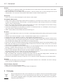
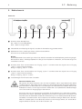
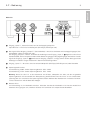
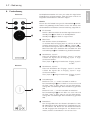
A2
KOPFHÖRERVERSTÄRKER
HEADPHONE AMPLIFIER
Bedienungsanleitung
Operating Instructions
A 2 – Sicherheit
2
1. Merkmale
•
•
•
•
•
•
•
•
Diskreter Aufbau der integrierten Audiobauteile
Zwei Kopfhörerausgänge, parallel geschaltet
Lautstärkeregler für beide Kopfhörerausgänge (ALPS-Potentiometer mit Motorsteuerung)
Zwei Eingänge, davon ein durchgeschleifter Eingang
zum Anschluss von Hochpegelsignalquellen (CD-Player, DVD-Player) und Verstärkern
Fernbedienung für alle Funktionen
Kopfhörerständer
Einstellbare Empfindlichkeit und Ausgangsimpedanz
Umschaltbare Netzspannung für 110 - 120 V und 220 - 240 V
2. Lieferumfang
•
•
•
•
•
•
•
Kopfhörerverstärker A 2
Fernbedienung RC 2
Kopfhörerständer
Befestigungsset für Kopfhörerständer
Netzkabel
Bedienungsanleitung
Sicherheitshinweise
3. Sicherheitsinformationen
1.
2.
3.
4.
5.
6.
7.
Bitte lesen Sie diese Anweisungen.
Bitte bewahren Sie diese Anweisungen auf.
Bitte beachten Sie alle Warnhinweise.
Folgen Sie allen Anweisungen.
Verwenden Sie dieses Gerät nicht in der Nähe von Wasser.
Reinigen Sie das Gerät nur mit einem trockenen Tuch.
Montieren Sie das Gerät nicht neben Hitzequellen wie Heizkörpern, Wärmespeichern, Öfen oder anderen Geräten
(auch Leistungsverstärkern), die Hitze abstrahlen.
8. Nehmen Sie keine Veränderungen am Netzstecker dieses Gerätes vor. Ein polarisierter Stecker hat zwei
Kontakte, von denen einer breiter ist als der andere. Ein geerdeter Stecker hat zwei Kontakte sowie einen
dritten Kontakt, der zur Erdung dient. Der breitere Kontakt beziehungsweise der Erdungskontakt dient Ihrer
Sicherheit. Wenn der Stecker an dem mit diesem Gerät gelieferten Kabel nicht zur Steckdose am Einsatzort
passt, lassen Sie die entsprechende Steckdose durch einen Elektriker ersetzen.
9. Sichern Sie das Netzkabel gegen Einquetschen oder Abknicken, insbesondere am Gerät selbst sowie an
dessen Netzstecker.
10. Verwenden Sie nur das vom Hersteller benannte Zubehör für dieses Gerät.
11. Trennen Sie das Gerät vom Stromnetz, wenn ein Gewitter aufkommt oder wenn Sie es voraussichtlich für längere
Zeit nicht verwenden werden.
12. Alle Wartungsarbeiten müssen von hierfür qualifizierten Servicemitarbeitern durchgeführt werden. Eine Wartung
ist erforderlich, wenn das Gerät selbst oder dessen Netzkabel beschädigt wurde, Flüssigkeiten oder Gegenstände in das Gerät gelangt sind, das Gerät Regen oder starker Feuchtigkeit ausgesetzt wurde, das Gerät nicht
ordnungsgemäß arbeitet oder es heruntergefallen ist.
Haftungsausschluss
• Die Firma beyerdynamic GmbH & Co. KG übernimmt keine Haftung für Schäden am Produkt oder Verletzungen
von Personen aufgrund unachtsamer, unsachgemäßer, falscher oder nicht dem vom Hersteller angegebenen Zweck
entsprechender Verwendung des Produkts.
3
Standort
• Das Gerät muss so aufgestellt werden, dass der Netzanschluss, Netzschalter und alle Anschlüsse auf der Rückseite des Gerätes leicht zugänglich sind.
• Wenn Sie das Gerät an einen anderen Ort transportieren, achten Sie darauf, dass es ausreichend gesichert ist und
niemand durch ein eventuelles Herunterfallen oder Stoßen am Gerät verletzt werden kann.
Brandschutz
• Stellen Sie niemals offene Brandquellen (z.B. Kerzen) auf das Gerät.
Feuchtigkeit / Wärmequellen
• Setzen Sie das Gerät niemals Regen oder hoher Feuchtigkeit aus. Installieren Sie es daher nicht in unmittelbarer Nähe von Swimming Pools, Duschanlagen, feuchten Kellerräumen oder sonstigen Bereichen mit außergewöhnlich hoher Luftfeuchtigkeit.
• Stellen Sie niemals mit Flüssigkeiten gefüllte Gegenstände (z.B. Vasen oder Trinkgläser) auf das Gerät. Flüssigkeiten in den Geräten können einen Kurzschluss verursachen.
• Installieren und betreiben Sie das Gerät auch niemals in unmittelbarer Nähe von Heizkörpern, Beleuchtungsanlagen oder anderen wärmeerzeugenden Geräten.
• Setzen Sie das Gerät niemals direkter Sonneneinstrahlung aus.
Anschluss
• Verlegen Sie alle Kabel stets so, dass sie nicht durch scharfe Gegenstände geknickt oder gar durchgetrennt werden
können.
• Verlegen Sie alle Anschlusskabel so, dass niemand darüber stolpern und sich verletzen kann.
• Schalten Sie bei allen Arbeiten an den Ein- und Ausgängen die Stromzufuhr aus.
• Überprüfen Sie, ob die Anschlusswerte mit der vorhandenen Netzstromversorgung übereinstimmen. Bei Anschluss
des Systems an die falsche Stromversorgung können ernsthafte Schäden entstehen. Eine falsche Netzspannung
kann das Gerät beschädigen oder einen elektrischen Schlag verursachen.
• Beachten Sie, dass für verschiedene Netzspannungen entsprechende Netzkabel und Anschlussstecker erforderlich sind.
• Wenn durch das Gerät eine Sicherung defekt oder ein Kurzschluss verursacht wurde, nehmen Sie es vom Netz
und lassen Sie es überprüfen und reparieren.
• Fassen Sie das Netzkabel nicht mit nassen Händen an. An den Kontaktstiften darf sich kein Wasser oder Staub
befinden. In beiden Fällen könnten Sie einen elektrischen Schlag erleiden.
• Das Netzkabel muss fest angeschlossen sein. Ist es lose, besteht Brandgefahr.
• Ziehen Sie das Netzkabel immer am Stecker vom Netz und/oder vom Gerät - niemals am Kabel. Das Kabel könnte
beschädigt werden und einen elektrischen Schlag oder Brand verursachen.
• Setzen Sie das Gerät nicht ein, wenn der Netzstecker beschädigt ist.
• Wenn Sie defektes oder ungeeignetes Zubehör anschließen, kann das Gerät beschädigt werden. Verwenden Sie
daher nur die von beyerdynamic lieferbaren oder empfohlenen Anschlusskabel.
• Zum Trennen des Gerätes vom Netz, schalten Sie es aus und ziehen Sie den Netzstecker aus der Netzsteckdose.
Reinigung
• Reinigen Sie das Gerät nur mit einem leicht feuchtem oder trockenem Tuch. Verwenden Sie niemals Lösungsmittel, da diese die Oberfläche beschädigen.
Fehlerbeseitigung / Reparatur
• Öffnen Sie nicht eigenmächtig das Gerät.
• Überlassen Sie alle Servicearbeiten nur autorisiertem Fachpersonal.
4. Entsorgung
Dieses Produkt darf am Ende seiner Lebensdauer nicht über den normalen Haushaltsabfall entsorgt
werden, sondern muss an einem Sammelpunkt für das Recycling von elektrischen und elektronischen Geräten abgegeben werden. Das Symbol auf dem Produkt, der Gebrauchsanweisung oder der
Verpackung weist darauf hin.
deutsch
A 2 – Sicherheit
A 2 – Bedienung
4
5. Bedienelemente
Vorderseite
Hinterleuchtete Standby-Taste.
Rot = Gerät ist im Standby-Modus.
Grün = Gerät ist eingeschaltet.
Infrarotdiode zum Empfang der Signale, die über die Fernbedienung gesendet werden.
Kopfhöreranschluss, parallel geschaltet, 6,35 mm Stereo-Klinke.
Zum Anschluss handelsüblicher Kopfhörer.
Wichtig:
Da die Kopfhörerbuchsen parallel geschaltet sind, wird die Lautstärke für beide Kopfhörer gemeinsam geregelt.
Wir empfehlen daher, unbedingt Kopfhörer mit der gleichen Impedanz zu verwenden, um für beide die gleiche
Lautstärke zu erzielen.
Hinterleuchtete Taste zum Auswählen von Eingang „Input 1“ und Aufschalten des Signals des an Eingang
„Input 1“ angeschlossenen Gerätes.
Orange = Eingang „Input 1“ ist aktiv.
Hinterleuchtete Taste zum Auswählen von Eingang „Input 2“ und Aufschalten des Signals des an Eingang
„Input 2“ angeschlossenen Gerätes.
Orange = Eingang „Input 2“ ist aktiv.
Lautstärkeregler zum Einstellen der Lautstärke.
Warnhinweis/Gehörschutz:
Wir möchten Sie darauf hinweisen, dass zu hohe Lautstärken und zu lange Hörzeiten das Gehör
schädigen können. Hörschäden stellen immer eine irreversible Beeinträchtigung des Hörvermögens dar. Drehen Sie daher bitte den Lautstärkeregler vor Inbetriebnahme und beim Wechsel der
Audioquellen zurück, da die angeschlossenen Geräte bzw. auch reproduzierte Audiodatenträger
sehr unterschiedliche Ausgangspegel haben können.
Achten Sie stets auf eine angemessene Lautstärke. Als Faustformel gilt: je höher die Lautstärke,
desto kürzer die Hörzeit. Gemäß der Berufsgenossenschaftlichen Vorschrift für Sicherheit und
Gesundheit bei der Arbeit BGV B3 darf die Lärmbelastung z.B. am Arbeitsplatz 85 dB (Zimmerlautstärke) nicht überschreiten. Dies entspricht einer maximal zulässigen Hörzeit von 8 Stunden.
Wird die Lautstärke jeweils um 3 dB erhöht, halbiert sich die zulässige Hörzeit, d.h. bei 88 dB beträgt die Hörzeit 4 Stunden, bei 91 dB 2 Stunden usw.
A 2 – Bedienung
deutsch
5
Rückseite
Eingang „Input 1“, Stereo-Cinchbuchsen für Hochpegelsignalquellen.
Input-Buchsen = Anschluss für Audioquelle (CD-Player, DVD-Player usw.)
Durchgeschleifter Ausgang „Output 1“ (hart verdrahtet) = Anschluss für Geräte mit Hochpegeleingängen (Stereoverstärker, aktive Lautsprecher usw.)
Am Ausgang „Output 1“ können Sie direkt das Audiosignal vom Eingang „Input 1“ abgreifen und an Ihren
Stereoverstärker, aktive Lautsprecher oder andere Geräte mit gängigen Hochpegeleingängen weiterleiten. Da das
Signal des Eingangs „Input 1“ permanent am Ausgang „Output 1“ anliegt, können Sie das durchgeschleifte
Audiosignal selbst bei ausgeschaltetem A 2 über Ihre Stereoanlage hören.
Eingang „Input 2“ = Anschluss für eine weitere Audioquelle (CD-Player, DVD-Player usw.) oder Verstärker
Spannungswahlschalter
Schalterstellung 230 V: für den Spannungsbereich 220 - 240 V
Schalterstellung 115 V: für den Spannungsbereich 110 - 120 V
Warnung: Bevor Sie den A 2 an das Stromnetz anschließen, überprüfen Sie bitte, ob der ausgewählte
Spannungsbereich mit der ortsüblichen Netzspannung übereinstimmt. Der Anschluss an eine andere Netzspannung bzw. ein Umschalten des Spannungswahlschalters während des Betriebs kann im Gerät einen Kurzschluss verursachen und das Gerät beschädigen.
Netzanschluss
Im Lieferumfang ist ein Netzkabel enthalten. Sollte der Stecker des Netzkabels nicht für den ortsüblichen
Stromanschluss geeignet sein, erwerben Sie bitte im Fachhandel ein entsprechendes Netzkabel.
A 2 – Bedienung
6
Unterseite
Ausgangsimpedanzschalter
Stellen Sie die Ausgangsimpedanz entsprechend der Impedanz des verwendeten Kopfhörers ein.
Empfohlene Einstellungen:
0Ω
= Bei Anschluss von niederohmigen Kopfhörern mit z.B. 16 Ω oder 32 Ω.
100 Ω = Bei Anschluss von mittel- und hochohmigen Kopfhörern mit z.B. 80 Ω, 250 Ω oder 600 Ω.
Hinweis:
In beiden Schalterstellungen ist der Kopfhörerausgang des A 2 gegen Kurzschluss geschützt.
Die Verstärkungsfaktoren des A 2 sind so kalibriert, dass beim Anschluss eines Kopfhörers mit 32 Ω in beiden
Schalterstellungen dieselbe Lautstärke erzielt wird.
Empfindlichkeitsschalter
Dient zur Anpassung an das angeschlossene Zuspielgerät und den Kopfhörer.
0 dB = Grundeinstellung (Auslieferzustand).
-4 dB = Bei Anschluss von Kopfhörern mit einem hohen Wirkungsgrad oder einem leistungsstarken Zuspielgerät.
+6 dB = Bei Anschluss von Kopfhörern mit einem niedrigen Wirkungsgrad oder einem leisen Zuspielgerät.
A 2 – Bedienung
7
Der Kopfhörerverstärker A 2 kann auch über die mitgelieferte
Fernbedienung gesteuert werden. Über die Tasten sind die im
Folgenden beschriebenen Funktionen möglich.
Vorderseite
Hinweis:
Richten Sie die Fernbedienung auf die Infrarotdiode am Verstärker. Für größtmögliche Reichweite achten Sie darauf, dass
der Verstärker keiner direkten Sonneneinstrahlung ausgesetzt ist.
Ein-/Austaste
Zum Ein- oder Ausschalten des am Netz angeschlossenen A 2.
Standby-Taste rot: Gerät ist im Standby-Modus.
Standby-Taste grün: Gerät ist eingeschaltet.
Mute-Taste
Zum Stummschalten des Kopfhörers.
Je nachdem welcher Eingang aktiv ist, erlischt am A 2 die
hinterleuchtete Taste für „Input 1“ oder „Input 2“ .
Die Stummschaltung kann durch nochmaliges Drücken der
Mute-Taste oder durch Verändern der Lautstärke mit dem
Lautstärkeregler der Fernbedienung deaktiviert werden.
Auswahltaste „Input 1“
Taste zum Auswählen des Eingangs „Input 1“ und Aufschalten des Signals des am Eingang „Input 1“ angeschlossenen Gerätes.
Taste „Input 1“ orange hinterleuchtet: Eingang „Input 1“
ist aktiv.
Auswahltaste „Input 2“
Taste zum Auswählen des Eingangs „Input 2“ und Aufschalten des Signals des an Eingang „Input 2“ angeschlossenen Gerätes.
Taste „Input 2“ orange hinterleuchtet: Eingang „Input 2“
ist aktiv.
Lautstärkeregler
Drücken Sie auf „+“, um die Lautstärke zu erhöhen.
Der Lautstärkeregler am A 2 dreht sich nach rechts und
die Taste „Input 1“ oder „Input 2“ am A 2 blinkt orange,
solange der Lautstärkeregler der Fernbedienung gehalten
wird.
Drücken Sie auf „-“, um die Lautstärke zu reduzieren.
Der Lautstärkeregler am A 2 dreht sich nach links und
die Taste „Input 1“ oder „Input 2“ am A 2 blinkt orange,
solange der Lautstärkeregler der Fernbedienung gehalten
wird.
Batteriefach
Zum Einlegen/Wechseln der Batterie (Knopfzelle Li-Mn,
CR 2032) öffnen Sie das Batteriefach. Verwenden Sie hierfür eine Münze und drehen Sie den Batteriefachdeckel
um 90° entgegen dem Uhrzeigersinn. Um Kratzer zu vermeiden, wickeln Sie die Münze in ein weiches Tuch.
Rückseite
deutsch
6. Fernbedienung
A 2 – Bedienung
8
7. Anwendungsbeispiel
Lautsprecher
Phono
PHONO IN
DVD-Player
DVD IN
TUNER IN
Endverstärker
CD IN
AUX OUT
TAPE OUT
TV IN
Tuner
Input 2
Output 1
Input 1
TV
CD-Player
A2
Kopfhörer
A 2 – Bedienung
9
• Schließen Sie an den Eingang „Input 1“ des A 2 einen CD-Player an.
• Schließen Sie den Ausgang „Output 1“ des A 2 an den CD-Eingang des Verstärkers an.
• Schließen Sie den Ausgang „Aux Out“ oder „Tape Out“ des Verstärkers an den Eingang „Input 2“ des A 2 an.
• Schließen Sie einen oder zwei Kopfhörer am Kopfhöreranschluss an. Je nach Wirkungsgrad und Impedanz des
Kopfhörers, können Sie die Empfindlichkeit und Ausgangsimpedanz auf der Unterseite des A 2 einstellen.
• Schließen Sie den A 2 über den Netzanschluss am Stromnetz an.
Warnung: Bevor Sie den A 2 an das Stromnetz anschließen, überprüfen Sie bitte, ob der über den Spannungswahlschalter ausgewählte Spannungsbereich mit der ortsüblichen Netzspannung übereinstimmt. Der Anschluss
an eine andere Netzspannung bzw. ein Umschalten des Spannungswahlschalters während des Betriebs kann
im Gerät einen Kurzschluss verursachen und das Gerät beschädigen.
• Sobald der A 2 an das Stromnetz angeschlossen wurde, leuchtet die Standby-Taste rot.
• Schalten Sie den A 2 über die Standby-Taste am A 2 oder über die Fernbedienung ein. Die Standby-Taste leuchtet grün und die Taste oder des beim letzten Ausschalten aktiven Eingangs leuchtet orange.
• Sie können nun mit den Tasten oder am A 2 oder über die Tasten oder der Fernbedienung eine von
den beiden Audioquellen auswählen, d.h. über die Taste „Input 1“ oder wählen Sie den CD-Player bzw. über
die Taste „Input 2“ oder ein anderes am Verstärker angeschlossenes Gerät wie z.B. TV, DVD-Player, Tuner
oder Phono aus.
• Das Signal des Eingangs „Input 1“ liegt zusätzlich permanent am Ausgang „Output 1“ an. Das bedeutet,
Sie können ohne Umstecken das durchgeschleifte Audiosignal selbst bei ausgeschaltetem A 2 über Ihre Stereoanlage hören.
• Stellen Sie die gewünschte Lautstärke mit dem Lautstärkeregler oder über die Fernbedienung ein.
• Soll der Kopfhörer vorübergehend stummgeschaltet werden, drücken Sie die Mute-Taste der Fernbedienung.
Die orange leuchtende Taste oder des ausgewählten Eingangs 1 oder 2 erlischt. Die Stummschaltung
deaktivieren Sie durch nochmaliges Drücken der Mute-Taste oder durch Betätigen des Lautstärkereglers über
die Fernbedienung.
• Zum Ausschalten des A 2 drücken Sie auf die Standby-Taste am A 2 oder auf die Taste der Fernbedienung.
• Eine von einem Microcontroller gesteuerte, intelligente Relaisschaltung sorgt dafür, dass Ihnen beim Umschalten von einer Audioquelle zur anderen, beim Ein- und Ausschalten des A 2 sowie bei einem Stromausfall kein
Knacken den Hörgenuss verdirbt oder das Gehör schädigt.
deutsch
Bedienhinweise zum Anwendungsbeispiel
10
A 2 – Bedienung
8. Montage Kopfhörerständer
Zur Aufbewahrung des Kopfhörers ist im Lieferumfang des Kopfhörerverstärkers A 2 ein Kopfhörerständer enthalten.
Diesen können Sie am A 2 montieren.
• Legen Sie das Gerät mit der Oberseite nach unten auf eine weiche Unterlage ganz vorne an die Tischkante.
• Legen Sie die Bohrungen des Kopfhörerständers auf die entsprechenden Bohrungen des Kopfhörerverstärkers
A 2. Siehe Zeichnung unten.
• Befestigen Sie den Kopfhörerständer mit den beiliegenden Inbusschrauben. Ziehen Sie die Inbusschrauben mit
dem Inbusschlüssel im Uhrzeigersinn fest.
A 2 – Technische Daten
11
Kopfhörerverstärker A 2
Frequenzgang . . . . . . . . .
Fremdspannungsabstand .
Klirrfaktor . . . . . . . . . . .
Eingangsimpedanz . . . . .
Ausgangsimpedanz . . . . .
Ausgangsleistung . . . . . .
.
.
.
.
.
.
.
.
.
.
.
.
.
.
.
.
.
.
.
.
.
.
.
.
.
.
.
.
.
.
.
.
.
.
.
.
.
.
.
.
.
.
.
.
.
.
.
.
.
.
.
.
.
.
.
.
.
.
.
.
.
.
.
.
.
.
.
.
.
.
.
.
.
.
.
.
.
.
.
.
.
.
.
.
1 Hz - 100 kHz (-1 dB)
>101 dB (unbewertet)
0,001% bei 170 mW/250 Ω
50 kΩ
Kopfhörerausgang 0 Ω/100 Ω (umschaltbar)
100 mW / 600 Ω
170 mW / 250 Ω
150 mW / 32 Ω
Kanaltrennung L/R . . . . . . . . . . . . . . . . . . . >89 dB
Maximalverstärkung . . . . . . . . . . . . . . . . . . 18 dB
Versorgungsspannung . . . . . . . . . . . . . . . . . 110 - 120 V / 220 - 240 V (umschaltbar), 50/60 Hz
Leistungsaufnahme (Betrieb) . . . . . . . . . . . . <15 W
Leistungsaufnahme (Standby) . . . . . . . . . . . <0,45 W
Audioanschlüsse . . . . . . . . . . . . . . . . . . . . . 2 x Line-Eingang, Cinchbuchsen vergoldet
1 x Line-Ausgang, Cinchbuchsen vergoldet
2 x Kopfhörerausgang, Klinkenbuchse 6,35 mm,
vergoldete Kontakte
Abmessungen (B x T x H) . . . . . . . . . . . . . . . 216 x 235 x 55 mm
Höhe inkl. Kopfhörerständer . . . . . . . . . . . . . 320 mm
Gewicht . . . . . . . . . . . . . . . . . . . . . . . . . . . 2230 g
Zubehör . . . . . . . . . . . . . . . . . . . . . . . . . . . IR-Fernbedienung, Kopfhörerständer, Netzkabel
Fernbedienung RC 2
Abmessungen (B x T x H) . . . . . . . . . . . . . . . 36 x 120 x 9 mm
Gewicht . . . . . . . . . . . . . . . . . . . . . . . . . . . 36 g
Batterie . . . . . . . . . . . . . . . . . . . . . . . . . . . 1 x CR 2032
deutsch
9. Technische Daten
12
A 2 – Safety
1. Features
•
•
•
•
•
•
•
•
Discrete design of the integrated audio components
Two headphone outputs connected in parallel
Volume control for both headphone outputs (motor controlled ALPS potentiometer)
Two inputs, one of them is looped-through to connect signal sources with high levels
(CD player, DVD player) and amplifiers
Remote control for all functions
Headphone stand
Selectable gain and output impedance
Switchable supply voltage for 110 - 120 V and 220 - 240 V
2. Supplied Accessories
•
•
•
•
•
•
•
A 2 Headphone Amplifier
RC 2 Remote Control
Headphone stand
Mounting set for headphone stand
Power cable
Manual
Safety Instructions
3. Safety Instructions
1.
2.
3.
4.
5.
6.
7.
Read these instructions.
Keep these instructions.
Heed all warnings.
Follow all instructions.
Do not use this apparatus near water.
Clean only with a dry cloth.
Do not install near any heat sources such as radiators, heat registers, stoves, or other apparatus (including
amplifiers) that produce heat.
8. Do not defeat the safety purpose of the polarized or grounding-type plug. A polarized plug has two blades with
one wider than the other. A grounding type plug has two blades and a third grounding prong. The wide blade
or the third prong are provided for your safety. If the provided plug does not fit into your outlet, consult an
electrician for replacement of the obsolete outlet.
9. Protect the power cord from being walked on or pinched particularly at plugs, convenience receptacles, and the
point where they exit from the apparatus.
10. Only use attachments/accessories specified by the manufacturer.
11. Unplug this apparatus during lightning storms or when unused for long periods of time.
12. Refer all servicing to qualified service personnel. Servicing is required when the apparatus has been damaged
in any way, such as power supply cord or plug is damaged, liquid has been spilled or objects have fallen into
the apparatus, the apparatus has been exposed to rain or moisture, does not operate normally, or has been
dropped.
Exemption from liability
• beyerdynamic GmbH & Co. KG will not be liable if any damage, injury or accident occurs due to negligent,
incorrect or inappropriate operation of the product.
Location
• The equipment must be set up so that the mains switch, mains plug and all connections on the rear of the
device are easily accessible.
• If you transport the equipment to another location take care to ensure that it is adequately secured and can never
be damaged by being dropped or by impacts on the equipment.
A 2 – Safety
13
Humidity / heat sources
• Never expose the equipment to rain or a high level of humidity. For this reason do not install it in the immediate
vicinity of swimming pools, showers, damp basement rooms or other areas with unusually high atmospheric
humidity.
• Never place objects containing liquid (e.g. vases or drinking glasses) on the equipment. Liquids in the equipment
could cause a short circuit.
• Do not install near any heat sources such as radiators, heat registers, stoves or other apparatus (including
amplifiers) that produce heat.
• Never expose the equipment to direct sunlight.
Connection
• Protect the power cord from being walked on or pinched particularly at plugs, convenience receptacles, and the
point where they exit from the apparatus.
• Lay all connection cables so that they do not present a trip hazard.
• Whenever working on the inputs and outputs of the equipment switch off power.
• Check whether the connection figures comply with the existing mains supply. Serious damage could occur due
to connecting the system to the wrong power supply. An incorrect mains voltage could damage the equipment or
cause an electric shock.
• Please note that different operating voltages require the use of different types of power cable and plugs.
• If the equipment causes a blown fuse or a short circuit, disconnect it from the mains and have it checked and
repaired.
• Do not hold the mains cable with wet hands. There must be no water or dust on the contact pins. In both cases
you could receive an electric shock.
• The mains cable must be firmly connected. If it is loose there is a fire hazard.
• Always pull out the mains cable from the mains and/or from the equipment by the plug – never by the cable. The
cable could be damaged and cause an electric shock or fire.
• Do not use the equipment if the mains plug is damaged.
• If you connect defective or unsuitable accessories, the equipment could be damaged. Only use connection
cables available from or recommended by beyerdynamic. If you use cables you have made up yourself, all claim
to warranty is null and void.
• In order to disconnect the receiver from AC power, switch it off and disconnect the power plug from the power
socket.
Maintenance
• Only clean the equipment with a slightly damp or dry cloth. Never use solvents as these damage the surface.
Troube shooting and servicing
• Do not open the equipment without authorisation. You could receive an electric shock. There are no userserviceable parts inside.
• Leave all service work to authorised expert personnel.
4. Disposal
This symbol on the product, in the instructions or on the packaging means that your electrical and
electronic equipment should be disposed at the end of its life separately from your household waste.
There are separate collection systems for recycling in the EU. For more information, please contact the
local authority or your retailer where you purchased the product.
english
Fire hazard
• Never place naked flames (e.g. candles) near the equipment.
A 2 – Operation
14
5. Controls and Indicators
Front view
Backlit standby button.
Red = Device is in standby mode.
Green = Device is turned on.
Infrared diode to receive the signals, which are transmitted via the remote control.
Headphone sockets, connected in parallel, 1/4" stereo jack (6.35 mm).
In order to connect standard headphones.
Important:
As the headphone sockets are connected in parallel, the volume is controlled for both headphones.
Therefore, we recommend using only headphones of the same impedance to achieve the same volume for both
headphones.
Backlit button to select input 1 and transmitting the signal of the device connected to input 1.
Orange = Input 1 is active.
Backlit button to select input 2 and transmitting the signal of the device connected to input 2.
Orange = Input 2 is active.
Volume control to adjust the volume.
Warning/hearing protection:
We would like to point out that listening at high volumes over a long period of time may damage
your hearing irreversibly. Therefore, reduce the volume before putting into operation and when
changing the audio source, as the connected devices or reproduced audio data can have very
different output levels.
Make sure that the set volume is not too high. Rule of thumb: The higher the volume, the
shorter the time of listening. According to employer’s regulations for safety and health the noise
exposure e.g. when working should not exceed 85 dB (low volume). This is an allowed time of
listening of 8 hours at maximum. If the volume is increased by 3 dB, the allowed time of listening
is halved, i.e. with 88 dB the time of listening is 4 hours, with 91 dB 2 hours and so on.
A 2 – Operation
15
english
Rear View
Input 1, stereo RCA phono sockets for signal sources with high levels.
Input sockets = for the connection of audio sources (CD player, DVD player etc.)
Looped-through output 1 (hard-wired) = for the connection of devices with high level inputs (stereo amplifiers,
active loudspeakers etc.)
At the output 1 you can pick up the audio signal from input 1 and route it to your stereo amplifier, active
loudspeakers or other devices with standard inputs for high levels. As the signal of the input 1 is permanently
available at output 1, you can listen to the looped-through audio signal via your hi-fi system, even when the
A 2 is turned off.
Input 2 = for the connection of another audio source (CD player, DVD player etc.) or amplifier
Voltage selector switch
Position of the switch 230 V: to select the voltage range of 220 - 240 V
Position of the switch 115 V: to select the voltage range of 110 - 120 V
Warning: Before connecting the A 2 to the mains, please check if the selected voltage range corresponds to the
local mains voltage. If you connect the device to a different mains voltage or if you change the position of the
voltage selector switch during operation, a short-circuit can occur inside the device and cause damage to the
device.
Mains connection
The A 2 is supplied with a power cable. If the connector of the power cable is not suitable for the local power
outlet, please purchase an appropriate power cable at your local dealer.
A 2 – Operation
16
Bottom
Output impedance switch
Select the output impedance according to the impedance of the headphone you are using.
Recommended settings:
0Ω
= When connecting headphones with a low impedance such as 16 Ω or 32 Ω.
100 Ω = When connecting headphones with a middle or high impedance such as 80 Ω, 250 Ω or 600 Ω.
Note:
In both settings the headphone output on the A 2 is protected against short-circuit.
The amplification factors of the A 2 are calibrated in a way that in both settings the same volume is achieved
when connecting a headphone with an impedance of 32 Ω.
Gain switch
To adapt the gain to the connected player and the headphone.
0 dB = Base setting (factory default setting).
-4 dB = When connecting headphones with a high efficiency or a high-performance player.
+6 dB = When connecting headphones with a low efficiency or a quiet player.
A 2 – Operation
17
6. Remote Control
Note:
Direct the remote control at the infrared diode of the amplifier.
To achieve a wide range, please make sure that the amplifier is
not exposed to direct sunlight.
On-off button
To turn on or off the A 2 which is connected to the mains.
Standby button red: Device is in standby mode.
Standby button green: Device is turned on.
Mute button
To mute the headphone.
Depending on the active input, the backlit button of the
A 2 for input 1 or input 2 will go out.
Mute can be deactivated by pressing the mute button once
again or by changing the volume with the volume control of the remote control.
Selector button “Input 1”
Button to select the input 1 and to transmit the signal of the
device connected to input 1 on the A 2.
Orange backlit button “Input 1” : Input 1 is active.
Selector button “Input 2”
Button to select the input 2 and to transmit the signal of the
device connected to input 2 on the A 2.
Orange backlit button “Input 2” : Input 2 is active.
Volume control
Press “+” to increase the volume.
The volume control on the A 2 will turn to the right and
the button for input 1 or input 2 on the A 2 will flash orange
as long as the volume control of the remote control is
pressed.
Rear View
Press “-” to reduce the volume.
The volume control on the A 2 will turn to the left and the
button for input 1 or input 2 on the A 2 will flash orange as
long as the volume control of the remote control is pressed.
Battery compartment
In order to insert/replace the battery (round cell Li-Mn,
CR 2032), please open the battery compartment. Use a
coin to turn the cover of the battery compartment 90° anticlockwise. In order to avoid scratches, wrap a soft cloth
around the coin.
english
The A 2 headphone amplifier can also be controlled via the
supplied remote control. The buttons allow the function described
below.
Front View
A 2 – Operation
18
7. Example of Application
Loudspeakers
Phono
PHONO IN
DVD player
DVD IN
TUNER IN
Power amplifier
CD IN
AUX OUT
TAPE OUT
TV IN
Tuner
Input 2
Output 1
Input 1
TV
CD player
A2
Headphones
A 2 – Operation
19
Operating Instruction for the Example of Application
• Connect a CD player to the input 1 on the A 2.
• Connect the output 1 on the A 2 to the CD input of the power amplifier.
• Connect one or two headphones to the headphone connection . Depending on the efficiency and the impedance
of the headphone, select the gain and the output impedance at the bottom of the A 2.
• Connect the A 2 via the mains connection to the mains.
Warning: Before connecting the A 2 to the mains, please check if the voltage range selected with the voltage
selector switch corresponds to the local mains voltage. If you connect the device to a different mains voltage
or if you change the position of the voltage selector switch during operation, a short-circuit can occur inside
the device and cause damage to the device.
• When the A 2 is connected to the mains, the standby button will illuminate red.
• Turn on the A 2 by pressing the standby button on the A 2 or the button of the remote control. The standby
button will illuminate green and the button or will illuminate orange, depending on which input was
active when the A 2 was turned off.
• Now you can select one of the two audio sources with the buttons or on the A 2 or with the buttons or of the remote control, i.e. with the button for input 1 or you select the CD player or with the button for
input 2 or you select another device connected to the amplifier such as a TV, DVD player, tuner or phono
player.
• The signal of input 1 is also permanently available at output 1 . This means you can listen to the loopedthrough audio signal via your hi-fi system, even when the A 2 is turned off.
• Select the desired volume with the volume control or via the remote control .
• If the headphone is to be muted temporarily, press the mute button of the remote control. The orange illuminating button or of the selected input 1 or 2 will go out. Deactive mute by pressing the mute button once
again or by pressing the volume control of the remote control.
• In order to turn off the A 2 press the standby button on the A 2 or the button of the remote control.
• An intelligent, microprocessor-controlled relay ensures silent switching between the two different audio sources
and avoids unpleasant noise or damage to your hearing should a power failure occur or when turning the A 2 on
or off.
english
• Connect the “AUX Out” or “Tape Out” output of the power amplifier to the input 2 on the A 2.
20
A 2 – Operation
8. How to Mount the Headphone Stand
The A 2 headphone amplifier is supplied with a headphone stand for storing the headphone. You can mount this stand
to the A 2.
• Put the device upside down on a soft pad to the very front on the edge of a table.
• Make sure that the holes of the headphone stand match the holes of the A 2 headphone amplifier. Refer to the
drawing below.
• Attach the headphone stand with the supplied Allen screws. Tighten the Allen screws by turning the Allen key
clockwise.
A 2 – Technical Specifications
21
A 2 Headphone Amplifier
Frequency response. . . . .
Signal-to-noise ratio . . . .
T.H.D. . . . . . . . . . . . . . .
Input impedance. . . . . . .
Output impedance . . . . .
Output power . . . . . . . . .
.
.
.
.
.
.
.
.
.
.
.
.
.
.
.
.
.
.
.
.
.
.
.
.
.
.
.
.
.
.
.
.
.
.
.
.
.
.
.
.
.
.
.
.
.
.
.
.
.
.
.
.
.
.
.
.
.
.
.
.
.
.
.
.
.
.
.
.
.
.
.
.
.
.
.
.
.
.
.
.
.
.
.
.
1 Hz - 100 kHz (-1 dB)
>101 dB (unweighted)
0.001% at 170 mW/250 Ω
50 kΩ
Headphone output 0 Ω/100 Ω (switchable)
100 mW / 600 Ω
170 mW / 250 Ω
150 mW / 32 Ω
Channel separation L/R . . . . . . . . . . . . . . . . >89 dB
Maximum gain . . . . . . . . . . . . . . . . . . . . . . 18 dB
Power supply . . . . . . . . . . . . . . . . . . . . . . . 110 - 120 V / 220 - 240 V (switchable), 50/60 Hz
Power consumption (operation) . . . . . . . . . . <15 W
Power consumption (standby). . . . . . . . . . . . <0.45 W
Audio connections. . . . . . . . . . . . . . . . . . . . 2 x line input, gold-plated RCA phono sockets
1 x line output, gold-plated RCA phono sockets
2 x headphone output, 1/4" stereo jack (6.35 mm),
gold-plated contacts
Dimensions (W x D x H) . . . . . . . . . . . . . . . . 216 x 235 x 55 mm
Height incl. headphone stand . . . . . . . . . . . . 320 mm
Weight . . . . . . . . . . . . . . . . . . . . . . . . . . . . 2230 g
Accessories . . . . . . . . . . . . . . . . . . . . . . . . . IR remote control, headphone stand, power cable
RC 2 Remote Control
Dimensions (W x D x H) . . . . . . . . . . . . . . . . 36 x 120 x 9 mm
Weight . . . . . . . . . . . . . . . . . . . . . . . . . . . . 36 g
Battery . . . . . . . . . . . . . . . . . . . . . . . . . . . . 1 x CR 2032
english
9. Technical Specifications
Weitere Vertriebspartner weltweit finden Sie unter www.beyerdynamic.com
For further distributors worldwide, please go to www.beyerdynamic.com
DE 1/BA A 2 (02.14)/642.487 • Abbildungen nicht vertragsbindend. Änderungen und Irrtümer vorbehalten • Non-contractual illustrations. Subject to change without notice.
beyerdynamic GmbH & Co. KG
Theresienstr. 8 | 74072 Heilbronn – Germany
Tel. +49 (0) 7131 617 - 0 | Fax +49 (0) 7131 617 - 204
[email protected] | www.beyerdynamic.com