1
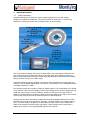
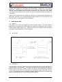
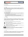
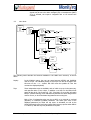
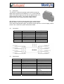
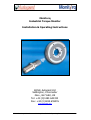
Monitorq
Industrial Torque Monitor
Installation & Operating Instructions
British Autogard Ltd
Siddington, Cirencester
Glos., GL7 6EU, UK
Tel: +44 (0)1285 640333
Fax: +44 (0)1285 659476
www.autogard.com
40611 Monitorq1 Manual
Monitorq Installation & Operating Instructions
-1-
Contents
1
GENERAL DESCRIPTION ................................................................................................................................................... 3
1.1
2
TORQUE RING ASSEMBLY................................................................................................................................................ 4
2.1
2.2
2.3
2.4
2.5
3
GENERAL:.......................................................................................................................................................................... 6
DIMENSIONS ...................................................................................................................................................................... 6
INSTALLATION .................................................................................................................................................................... 6
BASIC WIRING.................................................................................................................................................................... 7
ANALOGUE OUTPUTS ........................................................................................................................................................ 7
TRIPS ................................................................................................................................................................................. 7
EXTERNAL RESET & START ................................................................................................................................................ 7
OTHER INPUTS................................................................................................................................................................... 8
SAFETY .............................................................................................................................................................................. 8
E520A - GETTING STARTED .............................................................................................................................................. 8
5.1
5.2
5.3
5.4
5.5
6
GENERAL ........................................................................................................................................................................... 5
DIMENSIONS ...................................................................................................................................................................... 5
E60RX SPECIFICATIONS .................................................................................................................................................... 5
INSTALLATION .................................................................................................................................................................... 5
E520A DISPLAY UNIT .......................................................................................................................................................... 6
4.1
4.2
4.3
4.4
4.5
4.6
4.7
4.8
4.9
5
GENERAL:.......................................................................................................................................................................... 4
SPECIFICATIONS ................................................................................................................................................................ 4
FITTING ............................................................................................................................................................................. 4
GUARDING......................................................................................................................................................................... 4
RESETTING ZERO ............................................................................................................................................................... 4
E60RX RECEIVER ................................................................................................................................................................. 5
3.1
3.2
3.3
3.4
4
SYSTEM DESCRIPTION: ...................................................................................................................................................... 3
PRE POWER-UP CHECKLIST ............................................................................................................................................... 8
POWER UP......................................................................................................................................................................... 8
SET-UP .............................................................................................................................................................................. 8
INSTALLER MODE .............................................................................................................................................................. 9
USER MODE .................................................................................................................................................................... 10
MAINTENANCE INSTRUCTIONS ................................................................................................................................... 11
6.1
6.2
6.3
REPLACING A FUSE. ......................................................................................................................................................... 11
BATTERY REPLACEMENT .................................................................................................................................................. 11
ZERO TORQUE SETTING ................................................................................................................................................... 12
7
MONITORQ TROUBLESHOOTING................................................................................................................................ 12
8
E70A10 CURRENT DATA MODULE................................................................................................................................ 14
8.1
8.2
8.3
9
DESCRIPTION................................................................................................................................................................... 14
CONNECTIONS ................................................................................................................................................................. 14
SPECIFICATIONS .............................................................................................................................................................. 14
E70V10 VOLTAGE DATA MODULE ............................................................................................................................... 15
9.1
9.2
9.3
10
DESCRIPTION................................................................................................................................................................... 15
CONNECTIONS ................................................................................................................................................................. 15
SPECIFICATIONS .............................................................................................................................................................. 15
E70S10 STATUS DATA MODULE................................................................................................................................ 16
10.1
10.2
10.3
DESCRIPTION................................................................................................................................................................... 16
CONNECTIONS ................................................................................................................................................................. 16
SPECIFICATIONS .............................................................................................................................................................. 16
11
APPENDIX A : E520A MENU NAVIGATION ............................................................................................................ 17
12
APPENDIX B : E520A ENTERING AND CHANGING VALUES............................................................................ 17
13
APPENDIX C: GOOD WIRING PRACTICES........................................................................................................... 18
14
APPENDIX D: E520A RELAY OPERATION DESCRIPTION: .............................................................................. 19
15
APPENDIX E: START & RESET WIRING CONNECTIONS: ............................................................................... 20
40611 Monitorq1 Manual
Monitorq Installation & Operating Instructions
-2-
1
1.1
General Description
System Description:
Autogard’s Monitorq is an electronic torque measuring system for use with rotating
equipment in industrial installations. The system consists of three parts: 1) Torque ring
assembly 2) Telemetry receiver and 3) Output device. As shown below.
T O R Q U E R IN G W IT H
IN T E G R A T E D
R A D IO
T R A N S M IT T E R
E60R X
TELEM ETRY
R E C E IV E R
E520A
TO RQUE
M O N IT O R
D IS P L A Y
U N IT
The Torque Ring is typically of the form as shown above. The outer flange is bolted to one
part of the drive train, and the inner flange to the other part. Strain gauges measure the
torque being transmitted through the Torque Ring and this data is converted via the integral
battery powered circuitry into a radio signal.
Autogard’s Telemetry receiver (E60RX), receives the radio signal from the Torque Ring and
converts it into an RS485 digital signal. The receiver is connected to one of Autogard’s Output
or Display modules by a cable.
The Monitorq system has a range of output or display options. The most popular is the E520A
Torque Monitor with a real time display of the torque reading and on-screen configurable trip
levels that can be used to control machinery, alarms, etc with the two in-built relays. In
addition, the E520A has two analogue outputs of the torque data (0-10V Output, and 4-20mA
Current Loop) that can be used for control purposes or data acquisition.
Autogard can also offer stand-alone modules that convert the RS485 data from the E-60RX
telemetry receiver into a current output (4-20mA) – the E70A module or a voltage output (010V) – the E70V Module. In addition, an E70S Status module can be used to indicate the
status of the telemetry and the torque ring battery. These modules can be used when a
display of the torque or user programmable trips are not required
40611 Monitorq1 Manual
Monitorq Installation & Operating Instructions
-3-
2
2.1
Torque Ring Assembly
General:
The torque ring is usually supplied as an assembly with adapters suitable for direct
connection into the user’s drive train. Adapter flanges are connected to the torque ring using
special fitted bolts that are factory fitted and torqued. The torque ring has no capacity to
absorb misalignments in the drive train. Any misalignment should be taken out using a
suitable flexible coupling. Please refer to Autogard’s full range of flexible coupling products.
Special consideration should be given if the torque ring is to be fitted inside a metal housing.
Close proximity of metal parts to the aerial ring may attenuate the radio signal and cause loss
of telemetry. As a guide, at least 50mm radial clearance is required. There is to be no
metalwork between the receiver and the torque ring as this would act as a barrier to the
radio signal.
2.2
Specifications
Operating temperature limits:
Torque sampling rate
Resolution
Accuracy
Radio Frequency
Radiated power
Battery
Battery life
2.3
0° to +60°C
100Hz
10 bit (0.2% FSD – bipolar)
+/- 5% Full Scale, at 20oC
27.145MHz (FM)
< 1µW
Maxell ER17/33(2/3A), Lithium Thionyl Chloride, 3.6V,
1700mAh (2 or 4 depending on Torque Ring Sise max)
6 Months for 2 battery Torque Rings
12 Months for 4 battery Torque Rings
Fitting
Using suitable equipment, support the torque ring assembly in position in the drive-train and
make connections to mating parts using suitable fasteners. See datasheet for dimensions and
details. It should be noted that the torque ring contains micro-electronic components and
load sensing elements. Although it has been designed to withstand normal handling and
operating loads, undue force should not be used when fitting. Avoid press fitting, impact
loads and, under no circumstances, should heat be applied. Care should also be taken not to
dislodge the plastic aerial ring from around the unit.
When installing the torque ring assembly, the bolts used must not protrude through the
adapter plates and make contact with the torque ring itself. This is likely to give erroneous
torque readings and could cause permanent damage to the torque ring.
2.4
Guarding
As with all rotating equipment, suitable guarding must be provided, in accordance with
statutory requirements and all local and national codes of practice.
2.5
Resetting Zero
All torque rings are adjusted to read zero torque in the free state before leaving the factory.
However, small zero offsets may be evident after installation. These are often due to lockedin torque in the shafting and connections, and are normal. In general, re-setting the zero is
not recommended or necessary. It is recommended that the TARE function on the E520A unit
should be used instead (see Section 5.5)
40611 Monitorq1 Manual
Monitorq Installation & Operating Instructions
-4-
3
3.1
E60RX Receiver
General
The E60RX radio receiver decodes signals from the torque ring and sends the data, via a
cable connection, to the output device. The receiver is housed in a standard M30 threaded
body that is mounted close to the torque ring. The receiving aerial is housed in the plastic
nose – this should be located such that it faces the torque ring.
3.2
Dimensions
3.3
E60RX Specifications
General Specification:
Supply Voltage
Output (Signal) Voltage
Cable Type
Maximum Cable Extension Length (Shielded)
Operating Temperature Range
Environmental Protection Rating
+12V (Supplied from E520A Unit)
RS-485
3m Type 7-2-6C Shielded 6mm OD
800m max
(0 to +60°C)
IP65
LED Functions:
LED Illuminated
Red
Green
Yellow
Meaning
Power OK
Radio Signal Detected
Not Used
Wiring:
Wire Colour
Red
Blue
Green
Yellow
3.4
Function
+12V DC
0V DC
+ Torque Signal
- Torque Signal
Connected to
E-520A terminal 1
E-520A terminal 2
E-520A terminal 3
E-520A terminal 4
Installation
The E60RX is mounted with the plastic nose facing the plastic section of the Torque Ring.
Using a suitable bracket (not supplied) securely mount the E60RX adjacent to the torque ring,
ensuring that it will not come into contact with any rotating parts. The distance between the
end of the E60RX and the Torque Ring should be 5mm or less.
40611 Monitorq1 Manual
Monitorq Installation & Operating Instructions
-5-
The E60RX cable should be routed to the E520A, ensuring that good practice is followed
regarding the avoidance of interference from motor cables. Please refer to the notes in
Appendix C – especially where variable speed drives (VSD’s) are used. The cable supplied
with the E-60RX is shielded and this should be connected to an earth point on the E520A.
Any extension cable should also be shielded. If required, Autogard can supply the E60RX with
a 60ft cable.
Make the cable connections to the E520A with reference to the details above and section 4.4.
With power switched on to the E520A and with batteries fitted in the Torque Ring, the red
and green LED’s on the E60RX should be illuminated.
4
4.1
E520A Display Unit
General:
The E520A is the control and display unit for the Monitorq system. The torque value is
displayed on the E520A screen and features are included for setting trip levels to activate
alarms, process control functions etc. Voltage and current loop outputs are also provided for
use with external monitoring and control equipment.
4.2
Dimensions
4.3
Installation
It is advisable to mount the E520A away from any Variable Speed Drives and preferably in a
separate cabinet. See Appendix C. The E520A is designed for panel mounting and requires a
square cut-out 91 x 91 mm (+0.5mm, -0.0mm). The power unit in the E520A is a universal,
“switch-mode” type and may be connected to any single phase supply in the range 100-240V
AC, 0.5A. The equipment must be installed by suitably qualified personnel in accordance with
statutory regulations and all local and national codes of practice.
40611 Monitorq1 Manual
Monitorq Installation & Operating Instructions
-6-
Insert the E520A into the panel from the front making sure that the sealing strip is in place.
Fit the panel clamps (supplied) to the sides of the unit, slide back so that they locate on the
plastic lugs and tighten the threaded pin to secure the unit to the panel.
4.4
Basic Wiring
Removable connector strips are provided with the E520A and these accept up to 2.5mm
diameter solid or stranded wire. Connect the mains supply and E60RX according to the basic
wiring diagram below. Users of the old E520 should note that the mains connections
have changed!
4.5
Analogue Outputs
The 0-10V voltage output and the 4-20mA current loop output are for connection to external
monitoring equipment, if required. The outputs are referred to 0V, but are floating from earth
so they may be connected to an earthed system without forming a ground loop. In both
cases, zero torque is at mid scale, i.e. at 5V and 12mA respectively.
4.6
Trips
The relays have both normally open (NO) and normally closed (NC) connections. The relays
change state in reaction to the trip settings. See 5.5. They stay in their normal condition on loss
of power. The user should ensure that they are used safely, especially in relation to motor
shutdown. Relays used for motor shutdown should always be configured to latch on trip. Nonlatching relays may typically be used to trigger an audible or visual alarm. Please see Appendix D
for further information about the Relay Operation
4.7
External Reset & Start
The 100-240V AC EXT RST and START inputs are wired up if remote resetting of the E520A
after a trip is required, or the motor START sensing function is selected. See section 5.5 for
40611 Monitorq1 Manual
Monitorq Installation & Operating Instructions
-7-
details of how to configure the function, and Appendix E for details of how these inputs
should be wired.
4.8
Other Inputs
Other inputs (RPM, AUX and 0-10V) are not used in this version of the E520A.
4.9
Safety
Once installation and wiring is complete, the E520A must be enclosed so that protection
against live (hazardous) parts is prevented, in accordance with statutory regulations. The
monitor must be fully isolated from all electrical power sources before carrying out any
installation, servicing or maintenance.
5
5.1
E520A - Getting Started
Pre power-up Checklist
Verify items in the following checklist before powering up the unit. Improper installation can
result in equipment damage.
• If motor shutdown is wired through one of the E520A’s internal relays, it should be wired
to ensure safe shutdown in the event of power loss.
• If any of the Analogue outputs have been wired (0-10V, 4-20mA) verify that they have
been wired back to the 0V connection on the E520A to prevent ground loops.
• The independent, primary disconnection device must comply with statutory wiring
regulations.
5.2
Power Up
After power is applied, the Autogard Logo screen is displayed on the E520A for a few seconds
followed by a second screen with company and contact information. The unit then displays
the normal “run-time” screen. The screen contrast can be adjusted if necessary by holding
the up or down arrow key for a few seconds.
As well as numerical data, the display incorporates the following status symbols:
Filled Circle – bottom RH corner
The unit is unable to detect a valid torque signal – e.g. no E60RX connected, torque
ring not in range or no telemetry being transmitted from the torque ring.
Unfilled Circle – bottom RH corner
An intermittent torque signal is detected – e.g. E60RX not close enough to ring,
signal from ring too weak, external interference present.
Crossed Battery Symbol – bottom LH corner
Battery charge in the torque ring is low. This may also be accompanied by the
“Unfilled Circle” symbol. This indicates that the batteries need to be replaced.
In normal operation these areas remain blank.
5.3
Set-up
The various E520A set-up options are accessed by holding down the front panel LEFT ARROW
key for a few seconds. This displays the initial SETUP menu. To return to normal running, use
the Up and Down arrow keys to select EXIT from the menu, then press the OK key.
40611 Monitorq1 Manual
Monitorq Installation & Operating Instructions
-8-
Two modes, INSTALL and USER, may be entered from the initial SETUP menu. The general
philosophy behind these two modes is that INSTALL is intended for initial set-up (usually on
commissioning) and USER is for customer settings. The HELP item on the menu gives Autogard
contact details that may be used if further assistance is required. To exit HELP, press OK.
Each mode enables various parameters to be set up, via a menu system. The UP and DOWN
arrows on the front panel move a cursor (>) through the menu. To select or change the status
of an item press OK. To adjust a value, use the UP and DOWN arrows. The LEFT and RIGHT
arrow keys are used to select the digit to be changed. To confirm an entry press OK. When the
value is set, press OK again. Further details of menu navigation are given in Appendix A, while
Appendix B details how the various levels, delays and values are set up.
5.4
Installer Mode
SETUP
> INSTALL
USER
HELP
EXIT
INSTALL
> TORQUE
OUTPUTS
EXIT
TORQUE
> CONFIG
IMPERIAL
RING TYPE
EXIT
OUTPUTS
> INST
EXIT
CONFIG
>Nm
F/SCALE
EXIT
OK
AV
kNm
OK
SET VALUE
IMPERIAL
> in lbs
EXIT
OK
ft lbs
RING TYPE
> 10 BIT
EXIT
OK
8 BIT
The following notes describe the functions available using the INSTALL menu, as shown above.
Full-scale Torque
The E520A must be set up so that the value for maximum torque
matches the full scale calibration marked on the torque ring. (This will
have been done at the factory.) Select CONFIG. The scale is set in
Nm or kNm. Select F/SCALE and, if not pre-set to the correct torque,
adjust to the required value.
Units
The choice of metric or imperial units is selected in the USER/DISPLAY
menu. The units of display (Nm. kNm, in-lbs or ft-lbs) are determined
by the settings in this menu. If METRIC is selected in USER, the units
set under INSTALL/CONFIG are used. If IMPERIAL is selected under
USER, the units set under IMPERIAL in the INSTALL menu are used.
Ring Type
For all Monitorq systems sold after mid 2001, the Ring Type setting
should be set to 10-BIT. Users with Strain Rings made before this date
may have to set this to the 8-BIT setting. Consult Autogard if in doubt.
40611 Monitorq1 Manual
Monitorq Installation & Operating Instructions
-9-
Outputs
5.5
The unit is provided with two analogue outputs: 0-10V or 4-20mA. The
signals may be set to be either averaged (AV) or instantaneous (INST)
If AV is selected, the output is integrated with a 0.25 second time
constant.
User Mode
SETUP
> INSTALL
USER
HELP
EXIT
USER
> DISPLAY
TRIPS
START
UTILS
EXIT
DISPLAY
> METRIC
POL ON
EXIT
TRIPS
>TRIP 1
TRIP 2
TRIP 3
T FLT OFF
RELAYS
EXIT
START
>OFF
DELAY
EXIT
UTILS
> VERSION
AVERAGE
TARE
EXIT
OK
OK
OK
IMPERIAL
POL INV
T FLT ON
OK
POL OFF
TRIP 1
> OFF
LEVEL
DELAY
RELAY 1
LATCH OFF
EXIT
OK
RELAYS
> RL1 NORM
RL2 NORM
EXIT
OK
ON
SET VALUE
O/LOAD
U/LOAD
SET VALUE
SET VALUE
OK
RELAY 2
OK
LATCH ON
OK
RL1 INV
OK
RL2 INV
VERSION
NUMBER
OK
TARE
> REAL
EXIT
PEAK
OK
NULL
The following notes describe the functions available in the USER menu structure, as shown
above.
Display
In the DISPLAY option, the user can swap between METRIC and IMPERIAL
units of torque. The indicated polarity of the torque can also be changed: POL
ON turns on the + or – symbol. POL OFF turns the symbols off. POL INV
reverses the displayed polarity
Trips
Three independent trips are available, each of which is set up in the same way,
and operates either of two relays, in addition a red LED on the E520A front
panel will also be lit. The fourth trip, T FLT (Trip-Fault), if set to ON, will switch
Relay 2 (without latching) when bad telemetry between the Strain Ring and the
receiver occurs, or when the Strain Ring batteries are running low.
Each of the 3 independent trips may be set OFF, or to respond to overload
(O/LOAD) or underload (U/LOAD) conditions. The LEVEL (the value of the
displayed parameter) at which the trip occurs is selectable, as well as the
DELAY following the trip level being passed. Each trip may operate either RELAY
1 or RELAY 2, and each trip may be latched if required.
40611 Monitorq1 Manual
Monitorq Installation & Operating Instructions
- 10 -
WARNING: If using the trips to control machinery it should be ensured that the
relays are wired, and the software configured, in such a way that if bad
telemetry or a power failure occurs, the system will behave in a safe manner.
Please see Appendix D for further information about the Relay configuration.
Start
When a motor driving a system is switched on, there is likely to be some
unusual torque peaks, etc whilst the system gets up to running speed. The
START function is included in the E520A to prevent these peaks activating the
TRIPS. If the START function is ON, when an AC Mains input is sensed on Pin
15 of the 15 Pin Connector, the START function is activated and the TRIPS will
ignore any torque value sensed until the time period set in DELAY has elapsed.
The LED labelled “R” on the front panel of the E-520A will be illuminated whilst
there is an AC input on pin 15.
Utilities
If PEAK is selected, then the E-520A displays the largest torque value seen
since the unit was turned on, Reset, or the Start function used. AVERAGE just
displays the normal torque output. The UTILS menu enables the installed
program VERSION to be displayed.
The TARE facility enables a system torque offset to be nulled. With the system
in its nominally zero-torque state, select TARE and set the option to NULL.
The E520A will then subtract the offset value and display the net torque –
this also nulls the analogue outputs. Note: the maximum offset that can be
nulled in this way is 10% of full scale. In normal operation, the TARE setting
should be REAL – i.e., the absolute value of torque transmitted by the torque
ring is displayed.
6
6.1
Maintenance Instructions
Replacing a fuse.
The E520A monitor must be fully isolated from all electrical power sources before carrying out
any installation, servicing or maintenance. Remove the E520A rear panel and withdraw the
power supply board (upper PCB). The fuse is located in a holder on the left hand side when
looking down on the board from the back. (See section 4.2). Remove the fuse and replace
with a ‘slow blow’ type T 315mA rating.
6.2
Battery replacement
When the “battery low” symbol appears on the E520A screen, all batteries should be replaced
at the same time. The replacement sequence is not important. The batteries are special high
capacity lithium type, 3.7V, size 2/3A, 1700mAh (4 batteries used for most units, 2 for
smaller torque rings). The approved brand is Maxell ER17/33. These may be obtained
commercially or be supplied by Autogard.
Access to the batteries is via radial ports (max 4) around the periphery of the plastic aerial
ring. The procedure is:
• Remove one of the battery caps (stainless steel slotted fitting in each port) by unscrewing
(anticlockwise) with a broad bladed tool. NB! Some models have locking grub screws
fitted through the face of the Monitorq ring. Please remove these first.
• The battery, which is spring loaded, will project out of its holder. It may be necessary to
use thin-nosed pliers to grip the battery button to remove it.
• Fit a new battery with the +ve end (button) facing radially outwards.
• Refit the battery cap. Do not over-tighten. Excessive force can damage the battery
holder.
• Repeat the procedure for the other batteries.
40611 Monitorq1 Manual
Monitorq Installation & Operating Instructions
- 11 -
WARNING!
6.3
Do not puncture, crush, or dispose of Lithium batteries in fire.
Observe local regulations for disposal.
Zero Torque Setting
If there is a zero torque offset present once the strain ring has been built into the system,
this can either be removed using the TARE function described in section 5.5, or by actually
adjusting the torque ring output itself. It should be noted that the Torque ring is calibrated at
the factory and changing the zero torque setting will effect the calibration. The zero
adjustment screw is accessible via a radial hole in the plastic aerial ring. Remove the labelled
screw plug (one of a pair of holes) and, using a long screwdriver, locate the small
potentiometer top located at the bottom of the hole. Rotate as required until zero is obtained
on the E520A display. Note: the other screw which is marked with tamperproof
paint, is for calibration setting and must not be adjusted. If in doubt, consult
Autogard.
7
Monitorq Troubleshooting
FAULT
POSSIBLE CAUSE
ACTION
7.1 Display does not
illuminate
Power disconnected
Check mains lead
attachment
Fuse blown in E520A
Check cause of overload and
replace fuse.
Supply voltage outside required
range (100-240V AC)
Contrast needs adjusting
Check supply voltage and
correct, if necessary.
In normal operating mode,
use up and down arrows to
adjust.
Normal RING TYPE is 10
BIT. If the torque ring is old,
(mid 2001 and earlier), the 8
BIT setting may have to be
used Consult Autogard if in
doubt.
7.2 Display difficult to read or
appears blank
7.3 Open circle in bottom left
corner of screen
Incorrect “RING TYPE” selected
on E520A
Radio signal from torque ring is
weak.
Adjust E60RX position to be
as close to ring as possible.
Check that nothing is
screening the receiver from
the aerial.
Move ring away from heavy
metalwork.
Interference present.
7.4 Solid circle in bottom left
hand corner of screen. No
green LED on E60RX, but red
LED ON.
40611 Monitorq1 Manual
No signal received from the
torque ring.
Check for external RF
signals.
Check position of E60RX.
Re-position if necessary.
Check battery condition.
(3.7V). Replace all batteries
if voltage is lower than 3.5
Monitorq Installation & Operating Instructions
- 12 -
Volts.
7.5 Solid circle in bottom left
hand corner of screen. No
green LED or red LED on
E60RX.
Power supply failure in E520A
7.6 E-520A screen “frozen”
7.7 Torque readings appear
incorrect
Processor “hang-up”
Data is corrupt due to weak
radio.
40611 Monitorq1 Manual
E60RX failure
Check for damage to the
aerial ring.
Check power supply. Should
be 12V on terminals 1 and 2
on 15 pin connector
Fit replacement E60RX
Power off, then power on.
See 7.3 above.
Incorrect full scale torque set
on E520A
Set full scale to match
torque ring per the rating
label.
Torque too low in relation to full
scale.
Check torque ring selection.
Consult Autogard re recalibration.
Large zero offset present
Check reading in expected
“zero” torque state. Adjust
offset as necessary.
Fixings interfering with torque
ring
Check mounting design and
ensure no customer fixings
touching torque ring
Monitorq Installation & Operating Instructions
- 13 -
8
8.1
E70A10 Current Data Module
Description
The E70A10 is a DIN rail mounting module which converts the
digital torque signals from the E60RX into a 4-20mA analog
signal. The output changes pro rata with the applied torque. A
12mA output equals zero torque, 20mA output equals maximum
positive torque and 4mA equals maximum negative torque.
LED indicators are used to show the status of the received torque
data, the status of the torque transducers battery and the status
of the E70A’s internal power supply. The E70A10 module
requires a +24 VDC supply, rated at 100mA. This is sufficient to power itself and the E60RX.
8.2
Connections
Terminal
1
2
3
4
5
6
7
8
8.3
Function
E70A10 Gnd
E70A10 Power
- (4-20 mA)
+(4-20 mA)
E60RX Power
E60RX Gnd
E60RX Data +
E60RX Data -
Connects To
24 VDC Supply
24 VDC Supply
Measuring Device
Measuring Device
E60RX Red Wire
E60RX Blue Wire
E60RX Green Wire
E60RX Yellow Wire
Specifications
Electrical
Supply Voltage
Supply Current
Analog Output
Output Resolution
Frequency Response
Input Signal
LEDs
Mechanical
Size
Location
Temperature
Environment
40611 Monitorq1 Manual
+24V
100mA (Max)
4-20mA
0.4% of Full Scale
30 Hz
RS-485 (From E60RX)
Data OK
Batt OK
Power OK
75(h) x 20(w) x 79.5(d) mm
DIN Rail Mounting
-40oC to +50oC
Monitorq Installation & Operating Instructions
- 14 -
9
9.1
E70V10 Voltage Data Module
Description
The E70V10 is a DIN rail mounting module which converts the
digital torque signals from the E60RX to a 0 to +10 volt analogue
signal. The output changes pro rata with the applied torque. A 5v
output equals zero torque, +10V output equals maximum
positive torque and 0V equals maximum negative torque.
LED indicators are used to show the status of the received torque
data, the status of the torque transducers battery and the status
of the E70V’s internal power supply. The E70V10 module requires a +24 VDC supply, rated at
100mA. This is sufficient to power itself and the E60RX.
9.2
Connections
Terminal
1
2
3
4
5
6
7
8
9.3
Function
E70V10 Gnd
E70V10 Power
0-10V Output
Analog Ground
E60RX Power
E60RX Gnd
E60RX Data +
E60RX Data -
Connects To
24 VDC Supply
24 VDC Supply
Measuring Device
Measuring Device
E60RX Red Wire
E60RX Blue Wire
E60RX Green Wire
E60RX Yellow Wire
Specifications
Electrical
Supply Voltage
Supply Current
Analogue Output
Output Resolution
Frequency Response
Input Signal
LEDs
Mechanical
Size
Location
Temperature
Environment
40611 Monitorq1 Manual
+24V
100mA (Max)
0-10 VDC
0.4% of Full Scale
30 Hz
RS-485 (From E60RX)
Data OK
Batt OK
Power OK
75(h) x 20(w) x 79.5(d) mm
DIN Rail Mounting
-40oC to +50oC
Monitorq Installation & Operating Instructions
- 15 -
10
E70S10 Status Data Module
10.1 Description
The E70S10 is a DIN rail mounting module which can only be used
with other Autogard E70 modules. It provided diagnostic signalling
that may be used by a PLC to monitor the operating status of a
Torque Ring and E60RX installation.
LED indicators are used to show the status of the received torque
data, the status of the torque transducers battery and the status of
the E70S10’s internal power supply. Relays are activated along with
these status indicators. The E70S10 module requires a +24VDC
supply, rated at 100mA. (Note that the E70S10 does not provide
power to the E60RX)
10.2 Connections
Terminal
1
2
3
4
5
6
Function
Power Fail
Power Fail
E70V10 Gnd
E70V10 Power
Invalid Data
Invalid Data
Connects To
Relay 3
Relay 3
24 VDC Supply
24 VDC Supply
Relay 2
Relay 2
11
12
13
14
Low Battery
Low Battery
E60RX Data+
E60RX Data-
Relay 1
Relay 1
E60RX Green Wire
E60RX Yellow Wire
10.3 Specifications
Electrical
Supply Voltage
Supply Current
Input Signal
LEDs
Relays
Mechanical
Environment
40611 Monitorq1 Manual
Relays Contacts
Size
Location
Temperature
+24V
100mA (from E-60RX)
RS-485 (From E60RX)
Data OK
Batt OK
Power OK
Relay 1 (Low Battery)
Relay 2 (Invalid data)
Relay 3 (Power Fail)
All 3 Relays are held normally
closed
0.5A @ 110 VAC max
75(h) x 30(w) x 70.5(d) mm
DIN Rail Mounting
-40oC to +50oC
Monitorq Installation & Operating Instructions
- 16 -
11 APPENDIX A : E520A Menu Navigation
Menus are navigated by way of the '>' cursor.
The cursor is moved by selection of UP ARROW or DOWN ARROW.
A menu 'wraps around' from both its top and bottom items when either UP ARROW is selected with the
cursor opposite the topmost item, or when DOWN ARROW is selected at the lowest item.
A menu item is selected by operation of the OK key.
Exit from a menu is affected by operation of the OK key when the cursor is opposite 'EXIT'.
When returning to a menu following the selection of an item, the cursor always positions itself next to the
topmost item, indicating the item it has returned from with a “*”.
12 APPENDIX B : E520A Entering and Changing Values
Entered values have four digits : 'leading zeroes' are acceptable.
Values entered may have no decimal point, a fixed decimal point position, or a selectable decimal point
position. On entry into a 'value entry' box, the left-most digit flashes, indicating that its value may be
changed if desired.
The value of a digit may be increased by use of the UP ARROW key, or decreased using the DOWN ARROW
key. 'Wraparound' occurs when incrementing from 9 (to 0), and when decreasing from 0 (to 9). A new digit
may be selected by use of either the RIGHT ARROW key or the LEFT ARROW key.
If the decimal point position is not selectable, operation of the RIGHT ARROW from the right-most digit
causes selection of the left-most digit. If the decimal point position is not selectable, operation of the LEFT
ARROW from the left-most digit causes selection of the right-most digit.
If the decimal point position is selectable, operation of the RIGHT ARROW key from the right-most digit
results in the left-most decimal point flashing. If there was a decimal point in that position to start with,
then it flashes. If there was no decimal point in that position, then a '*' symbol flashes. A new decimal point
position may be selected by use of the RIGHT ARROW key, while operation of the LEFT ARROW key returns
to the right-most digit.
If the decimal point position is selectable, operation of the LEFT ARROW key from the left-most digit results
in the right-most decimal point flashing. If there was a decimal point in that position to start with, then it
flashes. If there was no decimal point in that position, then a '*' symbol flashes. A new decimal point
position may be selected by use of the LEFT ARROW key, while operation of the RIGHT ARROW key returns
to the left-most digit.
A decimal point may be fixed at the current position by operation of either the UP ARROW key or the DOWN
ARROW key, when the flashing '*' symbol in the selected position becomes a flashing decimal point. Any
existing decimal point in another position is erased when a new position is selected.
40611 Monitorq1 Manual
Monitorq Installation & Operating Instructions
- 17 -
13 APPENDIX C: Good Wiring Practices
Background
These notes cover “good installation practice” and apply especially for data systems installed in the vicinity
of electronic variable speed drives. These are often referred to as VSD’s or VFD’s (variable frequency
drives).
Technical Information
VSD’s work by generating voltage and current signals that are fed directly to the motor. These signals are
generated within the VSD, giving full control over their amplitude, frequency and phase relationship.
There are several methods of generating the signals, all of them employing some form of square wave
modulation technique to approximate a sine wave. As a consequence of this, unwanted high frequency
harmonics are generated which can interfere with other equipment. In the case of the Monitorq system,
the most likely effect is to corrupt the digital torque signal.
Mains Cables
Most VSD manufacturers recommend the use of shielded cables for connection of the VSD to the mains
service supply. This would normally be a 4-core (3 phases and earth) cable and should be connected in
accordance with the VSD manufacturer’s instructions.
Since the E520A derives its power from the mains service supply, it is important that this supply is kept as
“clean” as possible. It may be necessary to add filters on to the mains input to the VSD to prevent the
“noise” it generates being superimposed back onto the mains supply and hence on to the E-520A.
Motor Cables
Most VSD manufacturers also recommend the use of shielded cables for connection of the VSD to the
motor. Again, this would normally be a 4-core (3 phases and earth) cable and should be connected in
accordance with the VSD manufacturer’s instructions. It is usual to keep these wiring runs as short as
possible to minimise the risk of radiated noise.
Earth Connections
Most VSD’s have an earth terminal which should be connected to an earth point provided for the purpose,
using heavy duty cable and the shortest possible route. This ensures a good electrical path for any noise to
pass to earth. It is the responsibility of the user to ensure that earthing conforms to national and local
codes of practice.
Control and Signal Cables
These and other signal or control cables should be wired away from mains and motor wires, since they are
likely to pick up the modulated signals going to the motor. It is again recommended that shielded cable is
used and that the shield is connected to a suitable earth point.
If control or signal cables have to run parallel to mains or motor cables, they should be separated by at
least 1 foot, adding another 1 foot for every additional 30 feet of parallel run.
If control or signal cables cross mains or motor cables, try to arrange them so that they cross at right
angles.
Positioning of the E520A
It is not advisable to mount the E520A in the same cabinet as a VSD. In extreme cases, it would be
possible for the VSD to radiate interference directly into the E520A (known as airborne interference), and
consequently corrupt incoming data from the E60RX.
40611 Monitorq1 Manual
Monitorq Installation & Operating Instructions
- 18 -
14 APPENDIX D:
E520A Relay Operation Description:
Definition of Terms:
Normally Open (NO)
Normally Closed (NC)
Single pole double throw
Relay contact is open while relay is de-energised.
Relay contact is closed while relay is de-energised.
Relay that has one common, one normally open
and one normally closed contact.
Relay is energised in tripped state.
Relay is de-energised in tripped state.
Plant will trip on loss of power to the E520a,
inverted configuration must be used to achieve
this.
"Normal" configuration
“Inverted" configuration
Fail safe
T FLT ON
Relay 2 will assume its tripped state if no
telemetry or low battery is detected (for fail safe
operation, relay 2 must be configured as
inverted).
Relay remains in tripped state until trip conditions
are cleared.
Relay remains in tripped state until trip conditions
are cleared and reset pushbutton or external reset
is operated.
If more than one trip is mapped to a relay, the
relay will assume its tripped state if any mapped
trip condition is detected.
Latch off
Latch on
Relay "mapping"
RELAY 2 CONFIGURED AS "NORMAL"
SHOWN IN NON-TRIPPED CONDITION (RELAY DE-ENERGISED)
SYSTEM IS NOT FAIL SAFE
L N
E-520A
RL2
RL2
RL2
RL1
RL1
RL1
NO
COM
NC
NO
COM
NC
RELAY 2 CONFIGURED AS "INVERTED"
SHOWN IN NON-TRIPPED CONDITION (RELAY ENERGISED)
SYSTEM IS FAIL SAFE
L
N
E-520A
RL2
RL2
RL2
RL1
RL1
RL1
40611 Monitorq1 Manual
NO
COM
NC
NO
COM
NC
Monitorq Installation & Operating Instructions
- 19 -
15 APPENDIX E: START & RESET wiring connections:
110-240
VAC
LIVE
NEUTRAL
RESET push
button switch
MOTOR
CONTACTOR
M
Note: Push button switch needs to be held down for 2-3 seconds to activate the RESET
function.
Addresses of spare parts stockists and service facilities
British Autogard Ltd
Siddington, Cirencester
Glos, GL7 6EU
England
American Autogard Corporation
5173 26th Avenue
Rockford, IL 61109
U.S.A.
Tel: +44 (0)1285 640333
Fax: +44 (0) 1285 659476
Email: [email protected]
Tel: +1 815 633 1441
Fax: +1 815 633 8488
Email: [email protected]
Autogard Kupplungen GmbH
Trifte 72
32657 Lemgo
Germany
Autogard Italia S.r.l
Via Udine 3,
20063 Cernusco sul Naviglio, Milano
Italy
Tel: +49 (0)5261 921258/9
Fax: +49 (0)5261 921260
Email: [email protected]
Tel: +39 (0)291 700471
Fax: +39 (0)291 700472
Email: [email protected]
Autogard Asia-Pacific Pty Ltd
Unit 17, 56 Keys Road
Cheltenham, Victoria 3192
Australia
Autogard Japan Ltd
15-16, 2- Chome, Takanawa
Minato-Ku, Tokyo 108
Japan
Tel: +61 (0) 39532 0901
Fax: +61 (0) 39532 1032
Email: [email protected]
Tel: +81 3 34499621
Fax: +81 3 54497491
Email: [email protected]
40611 Monitorq1 Manual
Monitorq Installation & Operating Instructions
- 20 -